EP0634274B1 - Dispositif d'impression - Google Patents
Dispositif d'impression Download PDFInfo
- Publication number
- EP0634274B1 EP0634274B1 EP94304282A EP94304282A EP0634274B1 EP 0634274 B1 EP0634274 B1 EP 0634274B1 EP 94304282 A EP94304282 A EP 94304282A EP 94304282 A EP94304282 A EP 94304282A EP 0634274 B1 EP0634274 B1 EP 0634274B1
- Authority
- EP
- European Patent Office
- Prior art keywords
- tape
- switch
- holding case
- tape holding
- zone
- Prior art date
- Legal status (The legal status is an assumption and is not a legal conclusion. Google has not performed a legal analysis and makes no representation as to the accuracy of the status listed.)
- Expired - Lifetime
Links
- 238000007639 printing Methods 0.000 title claims description 46
- 239000010410 layer Substances 0.000 description 13
- 239000000853 adhesive Substances 0.000 description 3
- 230000001070 adhesive effect Effects 0.000 description 3
- 239000012790 adhesive layer Substances 0.000 description 2
- 239000003086 colorant Substances 0.000 description 1
- 238000010276 construction Methods 0.000 description 1
- 230000000694 effects Effects 0.000 description 1
- 238000003780 insertion Methods 0.000 description 1
- 230000037431 insertion Effects 0.000 description 1
- 238000000034 method Methods 0.000 description 1
- 230000003287 optical effect Effects 0.000 description 1
- 238000007651 thermal printing Methods 0.000 description 1
Images

Classifications
-
- B—PERFORMING OPERATIONS; TRANSPORTING
- B41—PRINTING; LINING MACHINES; TYPEWRITERS; STAMPS
- B41J—TYPEWRITERS; SELECTIVE PRINTING MECHANISMS, i.e. MECHANISMS PRINTING OTHERWISE THAN FROM A FORME; CORRECTION OF TYPOGRAPHICAL ERRORS
- B41J15/00—Devices or arrangements of selective printing mechanisms, e.g. ink-jet printers or thermal printers, specially adapted for supporting or handling copy material in continuous form, e.g. webs
- B41J15/04—Supporting, feeding, or guiding devices; Mountings for web rolls or spindles
- B41J15/044—Cassettes or cartridges containing continuous copy material, tape, for setting into printing devices
-
- B—PERFORMING OPERATIONS; TRANSPORTING
- B41—PRINTING; LINING MACHINES; TYPEWRITERS; STAMPS
- B41J—TYPEWRITERS; SELECTIVE PRINTING MECHANISMS, i.e. MECHANISMS PRINTING OTHERWISE THAN FROM A FORME; CORRECTION OF TYPOGRAPHICAL ERRORS
- B41J3/00—Typewriters or selective printing or marking mechanisms characterised by the purpose for which they are constructed
- B41J3/407—Typewriters or selective printing or marking mechanisms characterised by the purpose for which they are constructed for marking on special material
- B41J3/4075—Tape printers; Label printers
-
- B—PERFORMING OPERATIONS; TRANSPORTING
- B41—PRINTING; LINING MACHINES; TYPEWRITERS; STAMPS
- B41J—TYPEWRITERS; SELECTIVE PRINTING MECHANISMS, i.e. MECHANISMS PRINTING OTHERWISE THAN FROM A FORME; CORRECTION OF TYPOGRAPHICAL ERRORS
- B41J35/00—Other apparatus or arrangements associated with, or incorporated in, ink-ribbon mechanisms
- B41J35/28—Detachable carriers or holders for ink-ribbon mechanisms
Definitions
- the present invention relates to a printing apparatus and is particularly concerned with thermal printing apparatus which receive tape holding cases housing a tape to be printed.
- Printing apparatus of the general type with which the present invention is concerned are known. They operate with a supply of tape arranged to receive an image and a means for transferring the image onto the tape.
- a tape holding case which holds a supply of image receiving tape and a supply of an image transfer ribbon, the image receiving tape and the transfer ribbon being passed in overlap through a printing zone of the printing device.
- a thermal print head cooperates which a platen to transfer an image from the transfer ribbon to the tape.
- a printing device operating with a tape holding case of this type is described for example in EP-A-0267890 (Varitronics, Inc.).
- Other printing devices have been made in which letters are transferred to an image receiving tape by a dry lettering or dry film impression process.
- the construction of the image receiving tape is substantially the same. That is, it comprises an upper layer for receiving an image which is secured to a releasable backing layer by a layer of adhesive.
- the upper layer can either receive an image on its top surface, its lower surface being secured to the releaseable backing layer by a layer of adhesive or alternatively the upper layer can be transparent and can receive an image on one of its faces printed as a mirror image so that it is viewed the correct way round through the other surface of the tape.
- a double sided adhesive layer can be secured to the upper layer, this double sided adhesive layer having a releaseable backing layer. This latter arrangement is described for example in EP-A-0322918 (Brother Kogyo Kabushiki Kaisha).
- the apparatus should include a way of identifying the width of tape within the tape holding case so that printing can be correctly carried out or inhibited where an incorrect tape is inserted. For example if tape of a narrower width is used, printing should be confined to the area of the narrow width tape and should not extend to a width suitable for a wider tape.
- tape holding cases having tapes of different widths are arranged to actuate different micro-switches when inserted into the printing device.
- the width of tape is identified by a variation in the external casing of the tape holding case.
- EP-A-0526078 the shape of a tape holding case interacts with an optical sensor to identify the width of tape therein.
- a discriminating switch is provided for discriminating between different colours of ink ribbon.
- the discriminating switch is only activated when a multicolour ink ribbon is housed in a cassette.
- the present invention seeks to provide a different solution to the problem of identification of different tape widths within a tape holding case, which is cheaper and simpler than the above mentioned solutions and which enables a user to positively set the tape width which he requires.
- a printing device comprising a zone for receiving a tape holding case which houses tape for printing, and a switch in said zone movable between at least first and second positions, characterised in that said zone for receiving the tape holding case is configured such that when the switch is in the first position, a cape holding case of a first type may be received in said zone without interference from the switch but a tape holding case of a second type can not be received in said zone due to interference from the switch and when the switch is in a second position a tape holding case of the second type can be received into said zone without interference from the switch but a tape holding case of the first type may not be received into said zone due to interference from the switch.
- the zone comprises a cassette receiving bay having a surface for receiving a tape holding case.
- that surface is provided with a slot and the switch has an actuating part which extends through the slot and above the surface of the cassette receiving bay.
- a tape holding case of the first type holds tape of a first width and is provided with a recess in a location which will receive the actuating part of the switch when the switch is in the first position.
- the tape holding case of the second type holds tape of a second width and is provided with a recess in a location which will receive the actuating part of the switch when it is in the second position. It will readily be appreciated that in other respects the tape holding cases are the same so that the external boundaries of the tape holding cases lie on a common perimeter defined by the cassette receiving bay.
- a user moves the actuating part of the switch into the position representing the tape width which he desires to use and then inserts the appropriate tape holding case. If an attempt is made to insert an incorrect tape holding case, this attempt will be foiled because the actuating part of the switch will prevent the tape holding case from being inserted.
- the switch is preferably connected to a microprocessor of the printing device to automatically advise the microprocessor of the width of tape which has been selected.
- a printing device and a tape holding case
- said printing device comprises a zone for receiving a tape holding case which houses tape for printing and a switch in said zone movable between at least first and second positions, characterized in that said zone for receiving the tape holding case is configured such that when the switch is in the first position, a tape holding case of a first type may be received in said zone without interference from the switch but a tape holding case of a second type can not be received in said zone due to interference from the switch and when the switch is in a second position a tape holding case of the second type can be received into said zone without interference from the switch but a tape holding case of the first type may not be received into said zone due to interference from the switch and said tape holding case is one of said first and second types and is received in said tape holding case zone, without interference from the switch, said switch being in the first position if said tape holding case is of the first type and being in the second position if said tape holding case is of said second type.
- a set of tape holding cases for use with the tape printing apparatus comprising at least two tape holding cases
- said tape printing apparatus includes a zone for receiving one of the tape holding cases characterized in that there is provided a switch in said zone movable between at least first and second positions, the switch having an actuating part which extends above a surface for receiving the tape holding case
- said first tape holding case contains a first type of tape and has a recess in a first location for receiving the actuating part of the tape printing apparatus only when the switch is in the first position
- said second tape holding case contains a second, different, type of tape and has a recess in a location different to that of the first location of the first tape holding case for receiving the actuation part of the tape printing device only when the switch is in the second position.
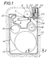
- Figure 1 illustrates in plan view a cassette bay of a printing device.
- the cassette bay is shown by the dotted line 2.
- the cassette bay includes a thermal print head 4 and a platen 6 which cooperate to define a print location P in a manner which is known in the art.
- the print head 4 is pivotable about a pivot point 8 so that it can be brought into contact with the platen 6 for printing and moved away from the platen to enable a cassette to be removed and replaced.
- a cassette inserted into the cassette bay 2 is denoted generally by reference numeral 10.
- the cassette holds a supply spool 12 of image receiving tape 14 which comprises an image receiving layer secured to a backing layer by a layer of adhesive.
- the image receiving tape 14 is guided by a guide mechanism (which is not shown) through the cassette, out of the cassette through an outlet O, past the print location P to a cutting location C.
- the cassette 10 also has an ink ribbon supply spool 16 and an ink ribbon take up spool 18.
- the ink ribbon 20 is guided from the ink ribbon supply spool 16 through the print location P and taken up on the ink ribbon take up spool 18.
- the image receiving tape 14 passes in overlap with the ink ribbon 20 through the print location P with its image receiving layer in contact with the ink ribbon.
- the platen 6 is driven so that it rotates to drive the image receiving tape 14 past the print location P during printing. In this way, tape is printed and fed out from the print location P to the cutting location C.
- the portion of the wall of the cassette 10 where the cutting location C is defined is denoted by reference numeral 22.
- a slot 24 is defined in this wall portion and the image receiving tape 14 is fed past the print location P to the cutting location C.
- the printing device inlcudes a cutting mechanism denoted generally by reference numeral 26.
- This cutting mechanism includes a cutter support member 28 which carries a blade 30.
- the blade 30 cuts the image receiving tape 14 and then enters the slot 24 with the leading part of its edge 31 first, rather than bearing against an anvil.
- the detailed operation of the cutting mechanism is described in our copending Application No. 94304284.6, published as EP-A-0 627 317.
- Figure 2 shows a partial diagrammatic section along the line II-II in Figure 1.
- reference numeral 3 denotes the floor of the cassette bay 2.
- Reference numeral 10 again denotes a cassette of a first type, for example holding an image receiving tape 14 having a first width of 12mm.
- Reference numeral 32 denotes a switch and reference numeral 34 denotes an actuating part of the switch.
- the switch 32 can be a standard low cost two position slide switch, conveniently mounted beneath the cassette bay floor 3, so that the actuating member protrudes above the cassette bay floor 3 through a slot 40.
- the actuating part 34 of the switch 32 is shown in a first position in Figure 2.
- the cassette 10 holding 12mm width tape has a recess 36 in its underside which is located to accommodate the actuating part 34 of the switch when it is in the first position.
- the switch 32 is connected to a microprocessor (not shown) via a connection 38 which carries a signal to the microprocessor identifying the position of the actuating member 34 of the switch. The microprocessor then uses this information to determine the width of tape which has been selected.
- the actuating part 34 of the switch 32 is movable into a second position which is shown in Figure 3. In the second position, it is intended to identify that a second tape width of for example 6mm is being used. Thus, a cassette of a second type housing a tape of a width of 6mm would have a recess located in a position to accommodate the actuating part 34 in its second position shown in Figure 3. This is not illustrated.
- Figure 3 illustrates however how the actuating member 34 of the switch 32 prevents an incorrect cassette from being inserted, with reference numeral 10 denoting a tape cassette having 12mm tape width and a recess 36 in a location intended to accommodate the actuating member 34 in its first position.
Landscapes
- Printers Characterized By Their Purpose (AREA)
- Impression-Transfer Materials And Handling Thereof (AREA)
- Handling Of Continuous Sheets Of Paper (AREA)
- Replacement Of Web Rolls (AREA)
- Dot-Matrix Printers And Others (AREA)
- Purses, Travelling Bags, Baskets, Or Suitcases (AREA)
Claims (8)
- Dispositif d'impression comprenant une zone (2) destinée à recevoir un boítier (10) portant une bande qui loge une bande (14) pour une impression, et un commutateur (32) dans ladite zone, mobile entre au moins des première et seconde positions, caractérisé en ce que ladite zone (2) destinée à recevoir le boítier (10) portant une bande est configurée de manière que, lorsque le commutateur (32) est dans la première position, un boítier (10) portant une bande d'un premier type peut être reçu dans ladite zone (2) sans que le commutateur (32) n'y fasse obstacle, mais qu'un boítier (10) portant une bande d'un second type ne puisse pas être reçu dans ladite zone (2) du fait que le commutateur (32) y fait obstacle, et lorsque le commutateur (32) est dans une seconde position, un boítier (10) portant une bande du second type puisse être reçu dans ladite zone sans que le commutateur n'y fasse obstacle, un boítier (10) portant une bande du premier type ne puisse pas être reçu dans ladite zone du fait que le commutateur (32) y fait obstacle.
- Dispositif d'impression selon la revendication 1, dans lequel la zone comprend un compartiment (2) de réception d'un boítier portant une bande, ayant une surface (3) destinée à recevoir un boítier portant une bande.
- Dispositif d'impression selon la revendication 2, dans lequel la surface est pourvue d'une fente (40) et le commutateur comporte une partie d'actionnement (34) qui s'étend à travers la fente et au-dessus de la surface (3) du compartiment de réception d'un boítier portant une bande.
- Dispositif d'impression selon la revendication 2 ou 3 en combinaison avec un boítier (10) portant une bande du premier ou du second type, dans lequel ledit commutateur comporte en outre une partie d'actionnement (34) qui s'étend au-dessus de la surface (3) du compartiment (2) de réception d'un boítier portant une bande, dans lequel un boítier (10) portant une bande du premier type porte une bande (14) d'une première largeur et est pourvu d'un évidement (36) en un emplacement qui recevra la partie d'actionnement (34) du commutateur (32) lorsque le commutateur (32) est dans la première position, et un boítier (10) portant une bande du second type porte une bande (14) d'une seconde largeur et est pourvu d'un évidement (36) en un emplacement qui recevra la partie (34) d'actionnement du commuteur (32) lorsqu'il est dans la seconde position.
- Dispositif d'impression selon l'une quelconque des revendications précédentes, qui comporte un microprocesseur auquel le commutateur (32) est connecté pour aviser automatiquement le microprocesseur de la position dudit commutateur.
- En combinaison, un dispositif d'impression de bande selon l'une quelconque des revendications précédentes avec boítier (10) de support du premier ou du second type.
- En combinaison, un dispositif d'impression et un boítier (10) portant une bande, dans lesquels ledit dispositif d'impression comporte une zone (2) destinée à recevoir un boítier (10) portant une bande qui loge une bande (14) pour une impression et un commutateur (32) dans ladite zone, mobile entre au moins des première et seconde positions, caractérisés en ce que ladite zone (2) destinée à recevoir le boítier (10) portant une bande est configurée de façon que, lorsque le commutateur (32) est dans la première position, un boítier (10) portant une bande d'un premier type puisse être reçu dans ladite zone (2) sans que le commutateur (32) n'y fasse obstacle, mais qu'un boítier (10) portant une bande d'un second type ne puisse pas être reçu dans ladite zone (2) du fait que le commutateur (32) y fait obstacle, et lorsque le commutateur (32) est dans une seconde position, un boítier (10) portant une bande du second type puisse être reçu dans ladite zone sans que le commutateur n'y fasse obstacle, mais un boítier (10) portant une bande du premier type ne puisse pas être reçu dans ladite zone du fait que le commutateur (32) y fait obstacle, et ledit boítier (10) portant une bande est de l'un desdits premier et second types et est reçu dans ladite zone (2) pour boítier portant une bande, sans que le commutateur (32) n'y fasse obstacle, ledit commutateur (32) étant dans la première position si ledit boítier (10) portant une bande est du premier type et étant dans la seconde position si ledit boítier portant une bande est dudit second type.
- En combinaison avec un dispositif d'impression de bande, un jeu de boítiers (10) portant des bandes à utiliser avec le dispositif d'impression de bande comportant au moins deux boítiers portant des bandes, où ledit dispositif d'impression de bande comprend une zone (2) destinée à recevoir l'un des boítiers (10) portant une bande, caractérisé en ce qu'il est prévu un commutateur (32) dans ladite zone (2), mobile entre au moins des première et seconde positions, le commutateur (32) ayant une partie d'actionnement (34) qui s'étend au-dessus d'une surface (3) destinée à recevoir le boítier (10) portant une bande, dans laquelle ledit premier boítier (10) portant une bande contient un premier type de bande (14) et présente un évidement (36) en un premier emplacement pour recevoir la partie d'actionnement (34) du dispositif d'impression de bande uniquement lorsque le commutateur (32) est dans la première position et ledit second boítier (10) portant une bande contient un second type, différent, de bande et présente un évidement (36) en un emplacement différent du premier emplacement du premier boítier portant une bande pour recevoir la partie (34) d'actionnement du dispositif d'impression de bande uniquement lorsque le commutateur (32) est dans la seconde position.
Applications Claiming Priority (2)
| Application Number | Priority Date | Filing Date | Title |
|---|---|---|---|
| GB939314387A GB9314387D0 (en) | 1993-07-12 | 1993-07-12 | Printing apparatus |
| GB9314387 | 1993-07-12 |
Publications (3)
| Publication Number | Publication Date |
|---|---|
| EP0634274A2 EP0634274A2 (fr) | 1995-01-18 |
| EP0634274A3 EP0634274A3 (fr) | 1995-07-26 |
| EP0634274B1 true EP0634274B1 (fr) | 1998-01-28 |
Family
ID=10738678
Family Applications (1)
| Application Number | Title | Priority Date | Filing Date |
|---|---|---|---|
| EP94304282A Expired - Lifetime EP0634274B1 (fr) | 1993-07-12 | 1994-06-14 | Dispositif d'impression |
Country Status (6)
| Country | Link |
|---|---|
| US (1) | US5540510A (fr) |
| EP (1) | EP0634274B1 (fr) |
| JP (1) | JP3490144B2 (fr) |
| AU (1) | AU673080B2 (fr) |
| DE (2) | DE634274T1 (fr) |
| GB (1) | GB9314387D0 (fr) |
Families Citing this family (31)
| Publication number | Priority date | Publication date | Assignee | Title |
|---|---|---|---|---|
| GB9523053D0 (en) * | 1995-11-10 | 1996-01-10 | Esselte Dymo Nv | Thermal printing device |
| DE59608999D1 (de) * | 1995-11-10 | 2002-05-08 | Esselte Nv | Satz von Bandkassetten und Druckgerät |
| DE59605247D1 (de) * | 1996-03-07 | 2000-06-21 | Esselte Nv | Mittel zur Detektion einer Kassette in einem Banddruckgerät |
| EP0958927B1 (fr) * | 1998-04-23 | 2003-10-29 | Esselte N.V. | Dispositif d'impression de ruban et cassette à ruban |
| GB9918039D0 (en) * | 1999-07-30 | 1999-09-29 | Esselte Nv | A printer with background images |
| GB9918042D0 (en) | 1999-07-30 | 1999-10-06 | Esselte Nv | Storage of labels in a printing device |
| GB0001913D0 (en) | 2000-01-27 | 2000-03-22 | Esselte Nv | Printing device |
| US6553305B2 (en) | 2000-12-29 | 2003-04-22 | Visteon Global Technologies, Inc. | Real time adaptive engine position estimation |
| GB0106016D0 (en) | 2001-03-12 | 2001-05-02 | Esselte Nv | Printing Device |
| EP1636776B1 (fr) * | 2003-06-20 | 2012-03-28 | Sanford, L.P. | Rouleau des etiquettes |
| GB0325264D0 (en) | 2003-10-29 | 2003-12-03 | Esselte B V B A | Vertical autosizing |
| GB2407536A (en) | 2003-10-30 | 2005-05-04 | Esselte | A label printing device |
| GB0418897D0 (en) | 2004-08-24 | 2004-09-29 | Esselte | Printing device |
| BRPI0923680B1 (pt) | 2008-12-25 | 2020-01-28 | Brother Kogyo Kabushiki Kaisha | fita cassete |
| PT2370265E (pt) * | 2008-12-25 | 2013-10-04 | Brother Ind Ltd | Cassete de fita e impressora de fita |
| JP5136503B2 (ja) | 2009-03-31 | 2013-02-06 | ブラザー工業株式会社 | テープカセット |
| WO2010113445A1 (fr) | 2009-03-31 | 2010-10-07 | Brother Kogyo Kabushiki Kaisha | Cassette à bande et imprimante sur bande |
| EP4067095B1 (fr) | 2009-03-31 | 2025-08-20 | Brother Kogyo Kabushiki Kaisha | Cassette de bande |
| JP4947085B2 (ja) * | 2009-03-31 | 2012-06-06 | ブラザー工業株式会社 | テープカセット |
| EP2415612B1 (fr) | 2009-03-31 | 2019-09-25 | Brother Kogyo Kabushiki Kaisha | Cassette à bande |
| US12296580B2 (en) | 2009-03-31 | 2025-05-13 | Brother Kogyo Kabushiki Kaisha | Tape cassette |
| CN104691118B (zh) | 2009-03-31 | 2017-10-13 | 兄弟工业株式会社 | 带盒 |
| DK2414165T3 (da) * | 2009-03-31 | 2014-05-05 | Brother Ind Ltd | Båndkassette og båndprinter |
| WO2010125114A1 (fr) * | 2009-04-28 | 2010-11-04 | Dymo | Cassette destinée à être utilisée dans une imprimante d'étiquettes |
| EP2261040B1 (fr) * | 2009-06-10 | 2012-02-08 | Brother Kogyo Kabushiki Kaisha | Imprimante |
| US8641304B2 (en) * | 2009-06-30 | 2014-02-04 | Brother Kogyo Kabushiki Kaisha | Tape cassette |
| EP2514600B1 (fr) | 2009-12-16 | 2015-01-21 | Brother Kogyo Kabushiki Kaisha | Cassette à bande |
| WO2011080840A1 (fr) | 2009-12-28 | 2011-07-07 | ブラザー工業株式会社 | Cassette à bande |
| JP5093265B2 (ja) * | 2010-02-26 | 2012-12-12 | ブラザー工業株式会社 | テープカセット |
| EP2371558B1 (fr) | 2010-03-31 | 2015-04-15 | Brother Kogyo Kabushiki Kaisha | Imprimante thermique |
| US8384750B2 (en) | 2010-03-31 | 2013-02-26 | Brother Kogyo Kabushiki Kaisha | Printing apparatus |
Family Cites Families (11)
| Publication number | Priority date | Publication date | Assignee | Title |
|---|---|---|---|---|
| JPS5993376A (ja) * | 1982-11-18 | 1984-05-29 | Matsushita Electric Ind Co Ltd | プリンタ |
| JPS59222380A (ja) * | 1983-06-02 | 1984-12-14 | Fujitsu Ltd | シリアルプリンタのリボン識別機構 |
| JPH0655539B2 (ja) * | 1986-01-27 | 1994-07-27 | 日本電気株式会社 | 印字装置の多色インクリボン切替機構 |
| JPS62292474A (ja) * | 1986-06-12 | 1987-12-19 | Fujitsu Ltd | カ−トリツジ |
| JPH0630449Y2 (ja) * | 1986-09-08 | 1994-08-17 | ブラザー工業株式会社 | 印字装置 |
| JP2535477Y2 (ja) * | 1987-11-25 | 1997-05-14 | 株式会社リコー | 感熱記録装置 |
| DE4022696A1 (de) * | 1989-07-18 | 1991-01-31 | Canon Kk | Verfahren und vorrichtung zur ausbildung von aufzeichnungen mittels eines mehrfarben-farbbandes |
| US5253334A (en) * | 1991-01-31 | 1993-10-12 | Casio Computer Co., Ltd. | Tape printer |
| MY124305A (en) * | 1991-01-31 | 2006-06-30 | Casio Computer Co Ltd | Tape printer. |
| JP2596263B2 (ja) * | 1991-07-22 | 1997-04-02 | ブラザー工業株式会社 | テープカセット製造方法及びテープカセット |
| JP2985911B2 (ja) * | 1992-01-08 | 1999-12-06 | ブラザー工業株式会社 | テープ印字装置におけるテープカセット装着構造 |
-
1993
- 1993-07-12 GB GB939314387A patent/GB9314387D0/en active Pending
-
1994
- 1994-06-14 DE DE0634274T patent/DE634274T1/de active Pending
- 1994-06-14 EP EP94304282A patent/EP0634274B1/fr not_active Expired - Lifetime
- 1994-06-14 DE DE69408225T patent/DE69408225T2/de not_active Expired - Lifetime
- 1994-06-27 US US08/266,818 patent/US5540510A/en not_active Expired - Lifetime
- 1994-07-07 AU AU67330/94A patent/AU673080B2/en not_active Ceased
- 1994-07-12 JP JP16024294A patent/JP3490144B2/ja not_active Expired - Fee Related
Also Published As
| Publication number | Publication date |
|---|---|
| JP3490144B2 (ja) | 2004-01-26 |
| EP0634274A3 (fr) | 1995-07-26 |
| DE69408225T2 (de) | 1998-05-28 |
| DE69408225D1 (de) | 1998-03-05 |
| US5540510A (en) | 1996-07-30 |
| JPH0768850A (ja) | 1995-03-14 |
| EP0634274A2 (fr) | 1995-01-18 |
| AU673080B2 (en) | 1996-10-24 |
| DE634274T1 (de) | 1995-11-30 |
| GB9314387D0 (en) | 1993-08-25 |
| AU6733094A (en) | 1995-01-19 |
Similar Documents
| Publication | Publication Date | Title |
|---|---|---|
| EP0634274B1 (fr) | Dispositif d'impression | |
| EP1132216B1 (fr) | Dispositif d'impression de bandes et cartouche à ruban utilisée dans le dispositif | |
| EP0512168B1 (fr) | Appareil d'impression pour ruban | |
| USRE43228E1 (en) | Tape cassette for use with a printing device | |
| US7559713B2 (en) | Label printer and printing medium | |
| EP0633141B1 (fr) | Cassette à ruban | |
| US5727888A (en) | Printer and a composite cassette including a tape cassette and a ribbon cassette used in the printer | |
| EP0607025B1 (fr) | Appareil d'impression avec cassette | |
| JP2998617B2 (ja) | テープカセットとリボンカセットとを含む複合カセット及びプリンタ | |
| EP1553033A2 (fr) | Support de rouleau en feuille et imprimante de ruban | |
| EP0574165B1 (fr) | Appareil d'impression | |
| US5857788A (en) | Thermal printing device with direct thermal cassette | |
| JPH08118738A (ja) | 印字テープ作成装置 | |
| JPH08216461A (ja) | 印字テープの作成装置及びそれに使用するカセット | |
| EP0607023B1 (fr) | Appareil d'impression pour ruban | |
| US6092946A (en) | Tape printing apparatus and tape holding case with a sliding switch | |
| EP1582364B1 (fr) | Imprimante à bande | |
| US6425328B2 (en) | Plate-making sheet and plate-making sheet printing device | |
| JP2024110516A (ja) | 印刷媒体およびテープカートリッジ | |
| JP3412860B2 (ja) | テープ印字装置 | |
| GB2306917A (en) | A thermal printing device with direct thermal cassette | |
| JP2998616B2 (ja) | テープカセットとリボンカセットとを含む複合カセット | |
| JP2002326397A (ja) | テープカセット | |
| JP2001063150A (ja) | プリンター | |
| JPH08230287A (ja) | リボンカセット |
Legal Events
| Date | Code | Title | Description |
|---|---|---|---|
| PUAI | Public reference made under article 153(3) epc to a published international application that has entered the european phase |
Free format text: ORIGINAL CODE: 0009012 |
|
| AK | Designated contracting states |
Kind code of ref document: A2 Designated state(s): DE FR GB IT |
|
| ITCL | It: translation for ep claims filed |
Representative=s name: BARZANO' E ZANARDO MILANO S.P.A. |
|
| EL | Fr: translation of claims filed | ||
| PUAL | Search report despatched |
Free format text: ORIGINAL CODE: 0009013 |
|
| AK | Designated contracting states |
Kind code of ref document: A3 Designated state(s): DE FR GB IT |
|
| 17P | Request for examination filed |
Effective date: 19950927 |
|
| DET | De: translation of patent claims | ||
| RAP1 | Party data changed (applicant data changed or rights of an application transferred) |
Owner name: ESSELTE N.V. |
|
| 17Q | First examination report despatched |
Effective date: 19961010 |
|
| GRAG | Despatch of communication of intention to grant |
Free format text: ORIGINAL CODE: EPIDOS AGRA |
|
| GRAG | Despatch of communication of intention to grant |
Free format text: ORIGINAL CODE: EPIDOS AGRA |
|
| GRAH | Despatch of communication of intention to grant a patent |
Free format text: ORIGINAL CODE: EPIDOS IGRA |
|
| GRAH | Despatch of communication of intention to grant a patent |
Free format text: ORIGINAL CODE: EPIDOS IGRA |
|
| GRAA | (expected) grant |
Free format text: ORIGINAL CODE: 0009210 |
|
| AK | Designated contracting states |
Kind code of ref document: B1 Designated state(s): DE FR GB IT |
|
| PG25 | Lapsed in a contracting state [announced via postgrant information from national office to epo] |
Ref country code: IT Free format text: LAPSE BECAUSE OF FAILURE TO SUBMIT A TRANSLATION OF THE DESCRIPTION OR TO PAY THE FEE WITHIN THE PRESCRIBED TIME-LIMIT;WARNING: LAPSES OF ITALIAN PATENTS WITH EFFECTIVE DATE BEFORE 2007 MAY HAVE OCCURRED AT ANY TIME BEFORE 2007. THE CORRECT EFFECTIVE DATE MAY BE DIFFERENT FROM THE ONE RECORDED. Effective date: 19980128 |
|
| REF | Corresponds to: |
Ref document number: 69408225 Country of ref document: DE Date of ref document: 19980305 |
|
| ET | Fr: translation filed | ||
| PLBE | No opposition filed within time limit |
Free format text: ORIGINAL CODE: 0009261 |
|
| STAA | Information on the status of an ep patent application or granted ep patent |
Free format text: STATUS: NO OPPOSITION FILED WITHIN TIME LIMIT |
|
| 26N | No opposition filed | ||
| REG | Reference to a national code |
Ref country code: GB Ref legal event code: IF02 |
|
| REG | Reference to a national code |
Ref country code: FR Ref legal event code: GC |
|
| REG | Reference to a national code |
Ref country code: GB Ref legal event code: 732E |
|
| REG | Reference to a national code |
Ref country code: FR Ref legal event code: RG |
|
| REG | Reference to a national code |
Ref country code: FR Ref legal event code: CD |
|
| PGFP | Annual fee paid to national office [announced via postgrant information from national office to epo] |
Ref country code: DE Payment date: 20120607 Year of fee payment: 19 |
|
| PGFP | Annual fee paid to national office [announced via postgrant information from national office to epo] |
Ref country code: GB Payment date: 20120613 Year of fee payment: 19 Ref country code: FR Payment date: 20120619 Year of fee payment: 19 |
|
| GBPC | Gb: european patent ceased through non-payment of renewal fee |
Effective date: 20130614 |
|
| REG | Reference to a national code |
Ref country code: FR Ref legal event code: ST Effective date: 20140228 |
|
| REG | Reference to a national code |
Ref country code: DE Ref legal event code: R119 Ref document number: 69408225 Country of ref document: DE Effective date: 20140101 |
|
| PG25 | Lapsed in a contracting state [announced via postgrant information from national office to epo] |
Ref country code: GB Free format text: LAPSE BECAUSE OF NON-PAYMENT OF DUE FEES Effective date: 20130614 Ref country code: DE Free format text: LAPSE BECAUSE OF NON-PAYMENT OF DUE FEES Effective date: 20140101 |
|
| PG25 | Lapsed in a contracting state [announced via postgrant information from national office to epo] |
Ref country code: FR Free format text: LAPSE BECAUSE OF NON-PAYMENT OF DUE FEES Effective date: 20130701 |