EP0634546A2 - Dispositif de limitation de rotation d'une serrure cylindrique relativement à un corps de véhicule - Google Patents
Dispositif de limitation de rotation d'une serrure cylindrique relativement à un corps de véhicule Download PDFInfo
- Publication number
- EP0634546A2 EP0634546A2 EP94110370A EP94110370A EP0634546A2 EP 0634546 A2 EP0634546 A2 EP 0634546A2 EP 94110370 A EP94110370 A EP 94110370A EP 94110370 A EP94110370 A EP 94110370A EP 0634546 A2 EP0634546 A2 EP 0634546A2
- Authority
- EP
- European Patent Office
- Prior art keywords
- panel
- outer cylinder
- cylinder housing
- radial
- radial projection
- Prior art date
- Legal status (The legal status is an assumption and is not a legal conclusion. Google has not performed a legal analysis and makes no representation as to the accuracy of the status listed.)
- Granted
Links
Images

Classifications
-
- E—FIXED CONSTRUCTIONS
- E05—LOCKS; KEYS; WINDOW OR DOOR FITTINGS; SAFES
- E05B—LOCKS; ACCESSORIES THEREFOR; HANDCUFFS
- E05B9/00—Lock casings or latch-mechanism casings ; Fastening locks or fasteners or parts thereof to the wing
- E05B9/08—Fastening locks or fasteners or parts thereof, e.g. the casings of latch-bolt locks or cylinder locks to the wing
- E05B9/084—Fastening of lock cylinders, plugs or cores
Definitions
- the present invention relates to an apparatus for restricting rotation of a cylinder lock including an outer cylinder housing and a key operated inner cylinder disposed in the outer cylinder housing, relative to a panel of a vehicle body.
- Japanese Utility Model Application First Publication No. 1-86658 discloses an apparatus for mounting an electronic lock on a panel of a vehicle body.
- the panel is formed with an opening including a hole defined by a circular peripheral edge of the panel and a radial cutout communicating with the hole.
- the electronic lock includes a cylindrical portion and a radial projection extending from the cylindrical portion. The cylindrical portion is disposed within the hole with the radial projection inserted into the radial cutout.
- An object of the present invention is to provide an apparatus including a panel with an opening and a cylinder lock disposed within the opening, which is capable of preventing rotation of the cylinder lock relative to the panel without any increase in thickness of the panel or any provision of a reinforcing member.
- an apparatus comprising: a panel formed with an opening including a hole defined by a circular peripheral edge of the panel and a radial cutout communicating with the hole; and a cylinder lock including an outer cylinder housing, a key operated inner cylinder disposed in the outer cylinder housing, and a radial projection extending from the outer cylinder housing; the outer cylinder housing being dIsposed within the hole with the radial projection inserted into the radial cutout; characterized in that the panel has an integral flap partly defining the radial cutout, the integral flap being turnable about a hinge line at which the panel abuts against the radial projection to withstand stress from the radial projection.
- an apparatus 10 includes a panel 12 of a vehicle body and a cylinder lock 14.
- the panel 12 is formed with an opening 16 including a hole 18 defined by a circular peripheral edge of the panel 12 and a plurality of radial cutouts 20 communicating with the hole 18.
- the cylinder lock 14 includes a flanged outer cylinder housing 22 and a key operated inner cylinder 24 disposed in the outer cylinder housing 22.
- the key operated inner cylinder 24 with a key slot 26 rotates in the outer cylinder housing 22 when the key operated inner cylinder 24 is subject to a torque with a proper key.
- the key operated inner cylinder 24 is operatively connected to a locking device 28 for locking a movable member such as door or hood, of the vehicle.
- the locking device 28 is so constructed and arranged within the vehicle as to be shiftable between a lock position in which a movement of the movable member is prevented and a release position in which the movement of the movable member is allowed.
- the locking device 28 shifts into the release position in response to rotation of the key operated inner cylinder 24 in a predetermined direction as indicated by the arrow R of Fig. 1, and into the lock position in response to rotation of the key operated inner cylinder 24 in a direction reverse to the direction R.
- a plurality of radial projections 30 extend outward from an outer periphery of a front portion of the outer cylinder housing 22 and join with a flange 32 of the outer cylinder housing 22.
- the outer cylinder housing 22 is disposed within the hole 18 with the radial projections 30 which are inserted into the radial cutouts 20, respectively.
- the panel 12 has a plurality of triangular integral flaps 34 partly defining the radial cutouts 20.
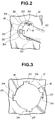
- Each of the integral flaps 34 is turnable about a hinge line 36 as shown in Fig. 4, at which the panel 12 abuts against the radial projection 30 to withstand stress from the radial projection 30.
- the integral flap 34 moves from a first position as indicated in the phantom line 42 of Fig. 4, into a second position as indicated in the solid line 44 of Fig. 4.
- the integral flap 34 has a leading end 46 remote from the hinge line 36 in abutting engagement with the radial projection 30 to withstand stress from the radial projection 30 when the outer cylinder housing 22 is subject to the torque of the magnitude smaller than the predetermined value. Then, the integral flap 34 is forced to turn about the hinge line 36 by the radial projection 30 to be placed in the second position.
- the integral flap 34 is formed with a bending edge 48 along the hinge line 36 in abutting engagement with the radial projection 30.
- the panel 12 has an increased structural strength at the bending edge 48, resulting from turning of the integral flap 34 about the hinge line 36.
- the panel 12 abuts against the radial projection 30 to withstand stress from the radial projection 30 when the outer cylinder housing 24 is subject to the torque of the magnitude greater than the predetermined value.
- Unitary rotation of the outer cylinder housing 22 and the key operated inner cylinder 24 in the direction R is caused in a predetermined range in the cutout 20 when the outer cylinder housing 22 is subject to the torque of the magnitude greater than the predetermined value.
- the integral flap 34 is so constructed and arranged as to restrict the unitary rotation in the direction R within the predetermined range in which the locking device 28 connected with the key operated inner cylinder 24 is kept in the lock position and prevented from shifting into the release position.
- the provision of the integral flap 34 serves for enhancing structural strength of the panel 12 which is capable of withstanding stress from the outer cylinder housing 22, without replacement of the panel with a panel having an increased thickness or without using any reinforcing member.
- unitary rotation of the outer cylinder housing 22 and the key operated inner cylinder 24 is restricted so that the locking device 28 is prevented from shifting into the release position.
- This simple construction and arrangement of the integral flap 34 serves for saving a manufacturing cost of the vehicle body.
- the apparatus of the invention serves for reduction in weight of the vehicle as compared with one utilizing a panel having an increased thickness or a reinforcing member for the enhancement of structural strength of the panel.
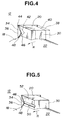
- Fig. 5 shows a modified cylinder lock of the apparatus according to the present invention, which only differs in provision of a guide groove 50.
- Like numerals denote like parts of the apparatus of the aforementioned first embodiment and therefore detailed explanations thereabout are omitted.
- the guide groove 50 extends on a face 52 of the radial projection 30 which abuts on the leading end 46 of the integral flap 34, in an axial direction of the outer cylinder housing 22.
- the guide groove 50 surely receives the leading end 46 of the integral flap 34 and serves for a smooth turn of the integral flap 34 about the hinge line 36.
Landscapes
- Engineering & Computer Science (AREA)
- Mechanical Engineering (AREA)
- Lock And Its Accessories (AREA)
Applications Claiming Priority (2)
| Application Number | Priority Date | Filing Date | Title |
|---|---|---|---|
| JP171947/93 | 1993-07-13 | ||
| JP17194793A JPH0726802A (ja) | 1993-07-13 | 1993-07-13 | キイシリンダの取付部構造 |
Publications (3)
| Publication Number | Publication Date |
|---|---|
| EP0634546A2 true EP0634546A2 (fr) | 1995-01-18 |
| EP0634546A3 EP0634546A3 (fr) | 1995-07-12 |
| EP0634546B1 EP0634546B1 (fr) | 1998-03-11 |
Family
ID=15932751
Family Applications (1)
| Application Number | Title | Priority Date | Filing Date |
|---|---|---|---|
| EP19940110370 Expired - Lifetime EP0634546B1 (fr) | 1993-07-13 | 1994-07-04 | Dispositif de limitation de rotation d'une serrure cylindrique relativement à un corps de véhicule |
Country Status (3)
| Country | Link |
|---|---|
| EP (1) | EP0634546B1 (fr) |
| JP (1) | JPH0726802A (fr) |
| DE (1) | DE69408911T2 (fr) |
Cited By (2)
| Publication number | Priority date | Publication date | Assignee | Title |
|---|---|---|---|---|
| WO2001044603A1 (fr) * | 1999-12-16 | 2001-06-21 | Assa Ab | Procede et dispositif permettant de fixer un corps de serrure |
| US9693885B2 (en) | 2007-03-30 | 2017-07-04 | DePuy Synthes Products, Inc. | Radiopaque markers for implantable stents and methods for manufacturing the same |
Families Citing this family (2)
| Publication number | Priority date | Publication date | Assignee | Title |
|---|---|---|---|---|
| JPH10273334A (ja) | 1997-03-28 | 1998-10-13 | Mitsubishi Rayon Co Ltd | 光ファイバ用切断装置及び切断方法 |
| US6598508B1 (en) | 1998-09-25 | 2003-07-29 | Mitsubishi Rayon Co., Ltd. | Optical fiber cutting device |
Family Cites Families (2)
| Publication number | Priority date | Publication date | Assignee | Title |
|---|---|---|---|---|
| FR2478174A1 (fr) * | 1979-11-30 | 1981-09-18 | Toyo Kogyo Co | Dispositif pour monter apres coup une serrure sur une porte d'automobile et procede d'assemblage d'une telle porte |
| JPH0186658U (fr) * | 1987-11-30 | 1989-06-08 |
-
1993
- 1993-07-13 JP JP17194793A patent/JPH0726802A/ja active Pending
-
1994
- 1994-07-04 EP EP19940110370 patent/EP0634546B1/fr not_active Expired - Lifetime
- 1994-07-04 DE DE1994608911 patent/DE69408911T2/de not_active Expired - Fee Related
Cited By (4)
| Publication number | Priority date | Publication date | Assignee | Title |
|---|---|---|---|---|
| WO2001044603A1 (fr) * | 1999-12-16 | 2001-06-21 | Assa Ab | Procede et dispositif permettant de fixer un corps de serrure |
| US6755060B2 (en) | 1999-12-16 | 2004-06-29 | Assa Ab | Method and device for fastening a lock body |
| AU775811B2 (en) * | 1999-12-16 | 2004-08-19 | Assa Ab | Method and device for fastening a lock body |
| US9693885B2 (en) | 2007-03-30 | 2017-07-04 | DePuy Synthes Products, Inc. | Radiopaque markers for implantable stents and methods for manufacturing the same |
Also Published As
| Publication number | Publication date |
|---|---|
| DE69408911T2 (de) | 1998-06-25 |
| EP0634546A3 (fr) | 1995-07-12 |
| DE69408911D1 (de) | 1998-04-16 |
| EP0634546B1 (fr) | 1998-03-11 |
| JPH0726802A (ja) | 1995-01-27 |
Similar Documents
| Publication | Publication Date | Title |
|---|---|---|
| US5722273A (en) | Latch bolt operating device | |
| US5438801A (en) | Quarter window opening/closing apparatus | |
| US20010003925A1 (en) | Actuator unit | |
| GB2052618A (en) | Hinge and hold-open assembly | |
| JP2007055546A (ja) | ステアリングロック機構 | |
| EP0634546B1 (fr) | Dispositif de limitation de rotation d'une serrure cylindrique relativement à un corps de véhicule | |
| US6094868A (en) | Handle unit of a manual window apparatus | |
| JP3576311B2 (ja) | ロック装置 | |
| JPH07133861A (ja) | 軸取付部材の回転規制構造 | |
| KR100501240B1 (ko) | 자동차용 도어아웃사이드핸들의 핸들이탈방지구조 | |
| US5476165A (en) | Fixing structure for outer ring member in one-way clutch | |
| JP2589146Y2 (ja) | 電動直線作動機の出力軸の回転止め構造 | |
| JPH0678132U (ja) | 自動変速機のパーキング機構 | |
| JP2525673Y2 (ja) | 車両用ドアハンドルの取付け構造 | |
| JPS60452Y2 (ja) | 自動車用ドアハンドル装置 | |
| JPH0230343Y2 (fr) | ||
| KR100435863B1 (ko) | 자동차용 스트라이커 | |
| JP2515818Y2 (ja) | 自動車のフューエルリッド装置 | |
| JP3659513B2 (ja) | 自動車用チェンジレバーの軸受け構造 | |
| JP2533005B2 (ja) | 車両ロック装置のスイッチ機構 | |
| JPH0422666Y2 (fr) | ||
| JPH0545727Y2 (fr) | ||
| JPS5853414Y2 (ja) | 車体の壁面等に回動自在に取付けられる部品 | |
| JPH0643381Y2 (ja) | スライドドアハンドル構造 | |
| JPH07259393A (ja) | ハンドル装置 |
Legal Events
| Date | Code | Title | Description |
|---|---|---|---|
| PUAI | Public reference made under article 153(3) epc to a published international application that has entered the european phase |
Free format text: ORIGINAL CODE: 0009012 |
|
| 17P | Request for examination filed |
Effective date: 19940704 |
|
| AK | Designated contracting states |
Kind code of ref document: A2 Designated state(s): DE FR GB |
|
| PUAL | Search report despatched |
Free format text: ORIGINAL CODE: 0009013 |
|
| AK | Designated contracting states |
Kind code of ref document: A3 Designated state(s): DE FR GB |
|
| GRAG | Despatch of communication of intention to grant |
Free format text: ORIGINAL CODE: EPIDOS AGRA |
|
| 17Q | First examination report despatched |
Effective date: 19970516 |
|
| GRAG | Despatch of communication of intention to grant |
Free format text: ORIGINAL CODE: EPIDOS AGRA |
|
| GRAH | Despatch of communication of intention to grant a patent |
Free format text: ORIGINAL CODE: EPIDOS IGRA |
|
| GRAH | Despatch of communication of intention to grant a patent |
Free format text: ORIGINAL CODE: EPIDOS IGRA |
|
| GRAA | (expected) grant |
Free format text: ORIGINAL CODE: 0009210 |
|
| AK | Designated contracting states |
Kind code of ref document: B1 Designated state(s): DE FR GB |
|
| REF | Corresponds to: |
Ref document number: 69408911 Country of ref document: DE Date of ref document: 19980416 |
|
| ET | Fr: translation filed | ||
| PLBE | No opposition filed within time limit |
Free format text: ORIGINAL CODE: 0009261 |
|
| STAA | Information on the status of an ep patent application or granted ep patent |
Free format text: STATUS: NO OPPOSITION FILED WITHIN TIME LIMIT |
|
| 26N | No opposition filed | ||
| PGFP | Annual fee paid to national office [announced via postgrant information from national office to epo] |
Ref country code: GB Payment date: 19990630 Year of fee payment: 6 |
|
| PGFP | Annual fee paid to national office [announced via postgrant information from national office to epo] |
Ref country code: DE Payment date: 19990706 Year of fee payment: 6 |
|
| PGFP | Annual fee paid to national office [announced via postgrant information from national office to epo] |
Ref country code: FR Payment date: 19990709 Year of fee payment: 6 |
|
| PG25 | Lapsed in a contracting state [announced via postgrant information from national office to epo] |
Ref country code: GB Free format text: LAPSE BECAUSE OF NON-PAYMENT OF DUE FEES Effective date: 20000704 |
|
| GBPC | Gb: european patent ceased through non-payment of renewal fee |
Effective date: 20000704 |
|
| PG25 | Lapsed in a contracting state [announced via postgrant information from national office to epo] |
Ref country code: FR Free format text: LAPSE BECAUSE OF NON-PAYMENT OF DUE FEES Effective date: 20010330 |
|
| REG | Reference to a national code |
Ref country code: FR Ref legal event code: ST |
|
| PG25 | Lapsed in a contracting state [announced via postgrant information from national office to epo] |
Ref country code: DE Free format text: LAPSE BECAUSE OF NON-PAYMENT OF DUE FEES Effective date: 20010501 |