EP0634579A1 - Dispositif pour obtenir un écoulement uniforme dans un système de dénitrification - Google Patents
Dispositif pour obtenir un écoulement uniforme dans un système de dénitrification Download PDFInfo
- Publication number
- EP0634579A1 EP0634579A1 EP94110163A EP94110163A EP0634579A1 EP 0634579 A1 EP0634579 A1 EP 0634579A1 EP 94110163 A EP94110163 A EP 94110163A EP 94110163 A EP94110163 A EP 94110163A EP 0634579 A1 EP0634579 A1 EP 0634579A1
- Authority
- EP
- European Patent Office
- Prior art keywords
- gas flow
- denitrification system
- exhaust gas
- uniform
- perforated plate
- Prior art date
- Legal status (The legal status is an assumption and is not a legal conclusion. Google has not performed a legal analysis and makes no representation as to the accuracy of the status listed.)
- Granted
Links
- 238000002347 injection Methods 0.000 claims abstract description 10
- 239000007924 injection Substances 0.000 claims abstract description 10
- 238000011144 upstream manufacturing Methods 0.000 claims abstract description 8
- 239000000126 substance Substances 0.000 claims abstract description 3
- 230000000694 effects Effects 0.000 abstract description 10
- 239000007789 gas Substances 0.000 description 43
- QGZKDVFQNNGYKY-UHFFFAOYSA-N Ammonia Chemical compound N QGZKDVFQNNGYKY-UHFFFAOYSA-N 0.000 description 18
- MWUXSHHQAYIFBG-UHFFFAOYSA-N nitrogen oxide Inorganic materials O=[N] MWUXSHHQAYIFBG-UHFFFAOYSA-N 0.000 description 14
- 229910021529 ammonia Inorganic materials 0.000 description 7
- 230000003068 static effect Effects 0.000 description 4
- 239000003054 catalyst Substances 0.000 description 2
- 239000000446 fuel Substances 0.000 description 2
- 229910000069 nitrogen hydride Inorganic materials 0.000 description 2
- 229910000831 Steel Inorganic materials 0.000 description 1
- 238000010276 construction Methods 0.000 description 1
- 238000004064 recycling Methods 0.000 description 1
- 230000001105 regulatory effect Effects 0.000 description 1
- 239000010959 steel Substances 0.000 description 1
Images
Classifications
-
- F—MECHANICAL ENGINEERING; LIGHTING; HEATING; WEAPONS; BLASTING
- F15—FLUID-PRESSURE ACTUATORS; HYDRAULICS OR PNEUMATICS IN GENERAL
- F15D—FLUID DYNAMICS, i.e. METHODS OR MEANS FOR INFLUENCING THE FLOW OF GASES OR LIQUIDS
- F15D1/00—Influencing flow of fluids
-
- F—MECHANICAL ENGINEERING; LIGHTING; HEATING; WEAPONS; BLASTING
- F23—COMBUSTION APPARATUS; COMBUSTION PROCESSES
- F23J—REMOVAL OR TREATMENT OF COMBUSTION PRODUCTS OR COMBUSTION RESIDUES; FLUES
- F23J15/00—Arrangements of devices for treating smoke or fumes
- F23J15/003—Arrangements of devices for treating smoke or fumes for supplying chemicals to fumes, e.g. using injection devices
Definitions
- the present invention relates to a device to make flow uniform used in an exhaust gas denitrification system.
- the conventional boiler is provided with a denitrification system to remove nitrogen oxides (NO x ) in exhaust gas.
- a denitrification system to remove nitrogen oxides (NO x ) in exhaust gas.
- an NO x removal catalyst is contained in this denitrification system.
- An ammonia injection nozzle for injecting ammonia (NH3) is provided on the upstream side of the denitrification system, and a device to make flow uniform for regulating the flow of exhaust gas is provided on the upstream side of the ammonia injection nozzle.
- the aforementioned device to make flow uniform consisting of a number of steel members etc. having a chevron-shaped cross section which are fixedly arranged in parallel or in a lattice shape in the exhaust gas flow path, achieves flow uniform effect only for a predetermined gas flow property.
- the shape of the lattice is such that the boiler is adapted to the exhaust gas flow rate at base load (high load). Therefore, the flow uniform effect cannot be achieved sufficiently for a low exhaust gas flow rate at partial loads. If the device to make flow uniform is constructed so as to achieve the flow regulation effect at partial loads, the pressure loss becomes excessive at high loads.
- An object of the present invention is to provide a device to make flow uniform in a denitrification system which can solve the above problems.
- the device to make flow uniform in a denitrification system in accordance with the present invention which is installed on the upstream side of a chemical injection means for the denitrification system, is composed of at least one perforated plate arranged across the gas flow, and the perforated plate can be turned from the closed position where the gas flow path is closed to the open position where the gas flow path is opened or vice versa.
- the perforated plate arranged across the gas flow is turned to close the gas flow path. Therefore, the gas flows through the holes in the perforated plate, so that a predetermined flow uniform is achieved.
- the perforated plate is turned to open the flow path, which maintains the predetermined flow regulation effect and prevents the increase in pressure loss.
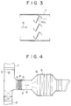
- the device to make flow uniform in accordance with this embodiment is incorporated between a boiler outlet duct and a denitrification system, for example, as shown in FIG. 4.
- the device 3 to make flow uniform is installed on the upstream side of an NH3 injection nozzle 5.
- the denitrification system is so constructed that an denitrification reactor 8, in which plural rows of NO x removal catalysts 6 are arranged, is installed to an exhaust gas duct 7 connected to a fuel economizer outlet duct 1 of a boiler etc. (not shown), and exhaust gas 9 containing nitrogen oxides (NO x ) flows therethrough.
- an denitrification reactor 8 On the upstream side of the denitrification reactor 8, a static device 4 to make flow uniform of a well-known construction and an ammonia injection nozzle 5 are installed.
- the device 3 to make flow uniform in accordance with the present invention is installed on the upstream side of these elements.
- Reference numeral 2 denotes an exhaust gas recycling duct connected to the fuel economizer outlet duct 1.
- the static device 4 to make flow uniform can be omitted.
- the exhaust gas duct 7 is arranged substantially in a horizontal position and its cross section is, for example, rectangular.
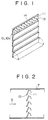
- a plurality of perforated plates 11 are arranged vertically across the flow of exhaust gas G in the rectangular exhaust gas duct 7, and many through holes 13 are formed in the perforated plate 11. The size and number of the hole 13 is determined depending on the exhaust gas flow rate etc.
- Each perforated plate 11 is formed into a rectangular blade shape having one side substantially equal to the width of the exhaust gas duct 7. For the perforated plate 11, its lower edge is installed to a rotating shaft 10 arranged horizontally across the flow of exhaust gas G indicated by the arrow as shown in FIG.
- the dumper-shaped device to make flow uniform is constructed in such a manner.
- the size and arrangement of the perforated plates are set so that when the perforated plates 11 are turned by the rotating shaft 10 or 10a and positioned vertically, the edge of the perforated plate 11 comes into contact with the edge of the adjacent perforated plate or the exhaust gas duct 7 so that the perforated plates come into a closed position where the exhaust gas flow path is closed (see FIG. 1).
- the rotating shafts 10, to which respective perforated plates are installed turn synchronously to the same angle in the same direction by a mechanism (not shown).
- Reference numeral 14 denotes a frame supporting the rotating shafts.
- the perforated plates when the load is low and the exhaust gas flow rate is low, the perforated plates assume the closed positions where the exhaust gas flow path is closed by the rotation of the rotating shafts 10 or 10a.
- the exhaust gas of a low flow rate passes through many holes 13 in the perforated plates so that the predetermined flow regulation effect can be achieved.
- the solid line in FIG. 1 indicates the closed position, while the broken line the open position.
- the device to make flow uniform of this embodiment is arranged in a denitrification system as shown in FIG. 4, when the load is high and in turn the exhaust gas flow rate is high, the device 3 to make flow uniform is opened and gas flow is unifying by the static device 4 to make flow uniform installed in the downstream.
- the distribution of gas flow velocity at the cross section of the ammonia injection nozzle 5 is within the average value ⁇ 30%, and the gas flow regulation effect can be achieved with low pressure loss due to the device 3 to make flow uniform.
- the flow uniform effect of the static device 4 to make flow uniform is little, and when the device 3 to make flow uniform is absent, the distribution of flow velocity at the cross section of the ammonia injection nozzle 5 increases to the average value ⁇ 80%, resulting in an decrease in denitrification property.
- the distribution of gas flow velocity at the cross section of the ammonia injection nozzle 5 becomes ⁇ 40%.
- the distribution of gas flow velocity can significantly be improved as compared with the case where the device to make flow uniform is not installed.
- perforated plates Although a plurality of perforated plates have been used in the above-described embodiment, one perforated plate may be used in the present invention. Also, in the above-described embodiment, the plural perforated plates have been arranged vertically at right angles to the horizontal exhaust gas duct. However, these plates may be arranged at an angle with respect to the vertical direction.
- the present invention achieves the predetermined flow uniform effect with low pressure loss by turning the perforated plates, which are arranged across the gas flow, in accordance with the gas flow rate.
Landscapes
- Engineering & Computer Science (AREA)
- Mechanical Engineering (AREA)
- General Engineering & Computer Science (AREA)
- Physics & Mathematics (AREA)
- Fluid Mechanics (AREA)
- Chemical & Material Sciences (AREA)
- Chemical Kinetics & Catalysis (AREA)
- General Chemical & Material Sciences (AREA)
- Treating Waste Gases (AREA)
- Chimneys And Flues (AREA)
- Exhaust Gas Treatment By Means Of Catalyst (AREA)
Applications Claiming Priority (2)
| Application Number | Priority Date | Filing Date | Title |
|---|---|---|---|
| JP1993037917U JP2596321Y2 (ja) | 1993-07-12 | 1993-07-12 | 脱硝装置におけるガス整流器 |
| JP37917/93 | 1993-07-12 |
Publications (2)
| Publication Number | Publication Date |
|---|---|
| EP0634579A1 true EP0634579A1 (fr) | 1995-01-18 |
| EP0634579B1 EP0634579B1 (fr) | 1998-09-16 |
Family
ID=12510901
Family Applications (1)
| Application Number | Title | Priority Date | Filing Date |
|---|---|---|---|
| EP94110163A Expired - Lifetime EP0634579B1 (fr) | 1993-07-12 | 1994-06-30 | Dispositif pour obtenir un écoulement uniforme de gas dans un système de dénitrification |
Country Status (4)
| Country | Link |
|---|---|
| US (1) | US5697403A (fr) |
| EP (1) | EP0634579B1 (fr) |
| JP (1) | JP2596321Y2 (fr) |
| DE (1) | DE69413328T2 (fr) |
Families Citing this family (11)
| Publication number | Priority date | Publication date | Assignee | Title |
|---|---|---|---|---|
| US6752795B2 (en) * | 2002-06-24 | 2004-06-22 | Bausch & Lomb Incorporated | Adjustable fluid flow resistor cassette |
| SE527104C2 (sv) * | 2004-05-21 | 2005-12-20 | Alstom Technology Ltd | Sätt och anordning för avskiljning av stoftpartiklar |
| US7882855B2 (en) * | 2006-09-05 | 2011-02-08 | Lincoln Foodservice Products, Llc | Air flow path for an air impingement finger duct |
| CN101450278B (zh) * | 2008-12-22 | 2011-04-06 | 西安热工研究院有限公司 | 整体机翼型均流与分区可调喷氨装置 |
| US8635858B2 (en) * | 2011-10-25 | 2014-01-28 | Ford Global Technologies, Llc | Fluid-spray atomizer |
| CN103055684B (zh) * | 2013-02-02 | 2015-06-10 | 山东大学 | 利用天然碱有效脱除烟气三氧化硫的装置及工艺 |
| JP6156628B2 (ja) * | 2013-04-17 | 2017-07-05 | 株式会社Ihi | 排煙脱硝装置及び排煙脱硝方法 |
| KR101684086B1 (ko) * | 2015-04-07 | 2016-12-07 | 현대자동차주식회사 | 차량용 히터의 유동 제어 배플 장치 |
| CN106669351A (zh) * | 2015-11-12 | 2017-05-17 | 上海霍林环保工程设备有限公司 | 一种脱硫除雾器内烟气流速的调节方法和装置 |
| JP7341779B2 (ja) * | 2019-08-05 | 2023-09-11 | 株式会社大気社 | 塗装ブース用の空調装置 |
| CN110836614B (zh) * | 2019-12-11 | 2025-01-24 | 南京能智电子科技有限公司 | 一种柜风路循环用换热器 |
Citations (6)
| Publication number | Priority date | Publication date | Assignee | Title |
|---|---|---|---|---|
| US4238455A (en) * | 1978-06-27 | 1980-12-09 | Ishikawajima-Harima Jukogyo Kabushiki Kaisha | Denitrification reactor |
| EP0053302A1 (fr) * | 1980-11-28 | 1982-06-09 | Carrier Corporation | Amortisseur de bruits de basse fréquence et de turbulences |
| DE8619685U1 (de) * | 1986-07-22 | 1986-09-04 | Mannesmann AG, 4000 Düsseldorf | Rauchgaskanal |
| DE3526575A1 (de) * | 1985-07-25 | 1987-02-05 | Lehmann Werke Ag | Katalysator zum einbau in abgasanlagen von insbesondere mit festbrennstoffen oder oel befeuerten kesseln |
| DE3637395A1 (de) * | 1986-11-03 | 1988-05-05 | Thyssen Industrie | Vorrichtung zur entstickung von rauchgasen |
| EP0502220A1 (fr) * | 1991-03-02 | 1992-09-09 | JOSEF BERTSCH Gesellschaft m.b.H & Co. | Chaudière à tubes d'eau |
Family Cites Families (12)
| Publication number | Priority date | Publication date | Assignee | Title |
|---|---|---|---|---|
| US2393170A (en) * | 1944-01-05 | 1946-01-15 | Selwyne P Kinney | Butterfly valve |
| US2667185A (en) * | 1950-02-13 | 1954-01-26 | James L Beavers | Fluid diverter |
| US3145642A (en) * | 1960-06-08 | 1964-08-25 | Air Guide Plastics Corp | Multi-louver grill |
| US4224826A (en) * | 1979-01-05 | 1980-09-30 | John McLoughlin | Flow measuring means |
| US4726563A (en) * | 1980-11-28 | 1988-02-23 | Carrier Corporation | Low frequency noise and turbulence reducer |
| DE3364257D1 (en) * | 1982-05-28 | 1986-07-31 | Shell Int Research | Mixing apparatus |
| US4506991A (en) * | 1982-06-07 | 1985-03-26 | Hudson Dannie B | Adjustable orifice for emulsifier |
| JPS63210551A (ja) * | 1987-02-27 | 1988-09-01 | Hitachi Plant Eng & Constr Co Ltd | 風量調節用ダンパ |
| US4887522A (en) * | 1987-05-22 | 1989-12-19 | Kabushiki Kaisha Kyoritsu | Air-conditioning apparatus |
| US5226213A (en) * | 1991-09-24 | 1993-07-13 | E. I. Du Pont De Nemours And Company | Rake valve for air-fiber streams |
| US5364303A (en) * | 1993-07-09 | 1994-11-15 | Summit Polymers, Inc. | Air vent adjustable vanes for controlling air flow direction |
| US8274046B1 (en) | 2011-05-19 | 2012-09-25 | Hermes Microvision Inc. | Monochromator for charged particle beam apparatus |
-
1993
- 1993-07-12 JP JP1993037917U patent/JP2596321Y2/ja not_active Expired - Fee Related
-
1994
- 1994-06-30 EP EP94110163A patent/EP0634579B1/fr not_active Expired - Lifetime
- 1994-06-30 DE DE69413328T patent/DE69413328T2/de not_active Expired - Fee Related
- 1994-07-07 US US08/271,513 patent/US5697403A/en not_active Expired - Fee Related
Patent Citations (6)
| Publication number | Priority date | Publication date | Assignee | Title |
|---|---|---|---|---|
| US4238455A (en) * | 1978-06-27 | 1980-12-09 | Ishikawajima-Harima Jukogyo Kabushiki Kaisha | Denitrification reactor |
| EP0053302A1 (fr) * | 1980-11-28 | 1982-06-09 | Carrier Corporation | Amortisseur de bruits de basse fréquence et de turbulences |
| DE3526575A1 (de) * | 1985-07-25 | 1987-02-05 | Lehmann Werke Ag | Katalysator zum einbau in abgasanlagen von insbesondere mit festbrennstoffen oder oel befeuerten kesseln |
| DE8619685U1 (de) * | 1986-07-22 | 1986-09-04 | Mannesmann AG, 4000 Düsseldorf | Rauchgaskanal |
| DE3637395A1 (de) * | 1986-11-03 | 1988-05-05 | Thyssen Industrie | Vorrichtung zur entstickung von rauchgasen |
| EP0502220A1 (fr) * | 1991-03-02 | 1992-09-09 | JOSEF BERTSCH Gesellschaft m.b.H & Co. | Chaudière à tubes d'eau |
Non-Patent Citations (1)
| Title |
|---|
| DATABASE WPI Section 768 Week 8224, Derwent World Patents Index; AN 82-H0033E * |
Also Published As
| Publication number | Publication date |
|---|---|
| DE69413328D1 (de) | 1998-10-22 |
| US5697403A (en) | 1997-12-16 |
| EP0634579B1 (fr) | 1998-09-16 |
| DE69413328T2 (de) | 1999-02-25 |
| JP2596321Y2 (ja) | 1999-06-14 |
| JPH079429U (ja) | 1995-02-10 |
Similar Documents
| Publication | Publication Date | Title |
|---|---|---|
| EP0634579B1 (fr) | Dispositif pour obtenir un écoulement uniforme de gas dans un système de dénitrification | |
| DE3875590T2 (de) | Denitrierungsreaktor. | |
| US4559275A (en) | Perforated plate for evening out the velocity distribution | |
| AU692616B2 (en) | Catalyst structure and gas purification apparatus | |
| DE3046921A1 (de) | Rechteckige gebuendelte festkoerperkatalysatoranordnung | |
| US4891052A (en) | Impingement type solids collector discharge restrictor | |
| US4143709A (en) | Tube support system | |
| JP3690804B2 (ja) | 原子炉における冷却材の制御 | |
| US20240017197A1 (en) | Filter having filter media sets which are arranged in a v-shaped manner and a frame | |
| US5820832A (en) | Plate-type catalytic converter | |
| KR102491279B1 (ko) | 배가스 정화 장치 | |
| JPS60244317A (ja) | 多煙道ボイラの煙道ガスの流れ偏向およびフライアツシユの分離を改良するための装置 | |
| KR20030024783A (ko) | 정류 장치를 구비한 배기 가스 처리 장치 | |
| JPH07213857A (ja) | ガス整流装置 | |
| CA2127818A1 (fr) | Dispositif de melange et de deflexion d'un fluide | |
| JPH0829222B2 (ja) | 脱硝装置のダスト除去装置 | |
| US5757874A (en) | Multi-spring strip spacer for nuclear fuel bundles | |
| JPH0780322A (ja) | 触媒ユニット | |
| JPS583736B2 (ja) | 触媒反応装置 | |
| CA2162718C (fr) | Catalyseur de plaque | |
| JP4086150B2 (ja) | 流体混合装置 | |
| JP2005036648A (ja) | 触媒反応装置 | |
| DE19647400A1 (de) | Plattenkatalysator | |
| JP2695666B2 (ja) | 触媒パックを備えた反応器 | |
| JPH11221447A (ja) | 触媒反応装置 |
Legal Events
| Date | Code | Title | Description |
|---|---|---|---|
| PUAI | Public reference made under article 153(3) epc to a published international application that has entered the european phase |
Free format text: ORIGINAL CODE: 0009012 |
|
| AK | Designated contracting states |
Kind code of ref document: A1 Designated state(s): DE IT |
|
| 17P | Request for examination filed |
Effective date: 19950203 |
|
| 17Q | First examination report despatched |
Effective date: 19961111 |
|
| GRAG | Despatch of communication of intention to grant |
Free format text: ORIGINAL CODE: EPIDOS AGRA |
|
| GRAG | Despatch of communication of intention to grant |
Free format text: ORIGINAL CODE: EPIDOS AGRA |
|
| GRAH | Despatch of communication of intention to grant a patent |
Free format text: ORIGINAL CODE: EPIDOS IGRA |
|
| GRAH | Despatch of communication of intention to grant a patent |
Free format text: ORIGINAL CODE: EPIDOS IGRA |
|
| GRAA | (expected) grant |
Free format text: ORIGINAL CODE: 0009210 |
|
| AK | Designated contracting states |
Kind code of ref document: B1 Designated state(s): DE IT |
|
| REF | Corresponds to: |
Ref document number: 69413328 Country of ref document: DE Date of ref document: 19981022 |
|
| PLBE | No opposition filed within time limit |
Free format text: ORIGINAL CODE: 0009261 |
|
| STAA | Information on the status of an ep patent application or granted ep patent |
Free format text: STATUS: NO OPPOSITION FILED WITHIN TIME LIMIT |
|
| 26N | No opposition filed | ||
| PGFP | Annual fee paid to national office [announced via postgrant information from national office to epo] |
Ref country code: DE Payment date: 20030710 Year of fee payment: 10 |
|
| PG25 | Lapsed in a contracting state [announced via postgrant information from national office to epo] |
Ref country code: DE Free format text: LAPSE BECAUSE OF NON-PAYMENT OF DUE FEES Effective date: 20050101 |
|
| PG25 | Lapsed in a contracting state [announced via postgrant information from national office to epo] |
Ref country code: IT Free format text: LAPSE BECAUSE OF NON-PAYMENT OF DUE FEES Effective date: 20050630 |