EP0634724B1 - Verarbeitungssystem mit gemeinschaftlichem Speicher - Google Patents
Verarbeitungssystem mit gemeinschaftlichem Speicher Download PDFInfo
- Publication number
- EP0634724B1 EP0634724B1 EP94401596A EP94401596A EP0634724B1 EP 0634724 B1 EP0634724 B1 EP 0634724B1 EP 94401596 A EP94401596 A EP 94401596A EP 94401596 A EP94401596 A EP 94401596A EP 0634724 B1 EP0634724 B1 EP 0634724B1
- Authority
- EP
- European Patent Office
- Prior art keywords
- node
- nodes
- super
- links
- serial
- Prior art date
- Legal status (The legal status is an assumption and is not a legal conclusion. Google has not performed a legal analysis and makes no representation as to the accuracy of the status listed.)
- Expired - Lifetime
Links
Images



Classifications
-
- G—PHYSICS
- G06—COMPUTING OR CALCULATING; COUNTING
- G06F—ELECTRIC DIGITAL DATA PROCESSING
- G06F15/00—Digital computers in general; Data processing equipment in general
- G06F15/16—Combinations of two or more digital computers each having at least an arithmetic unit, a program unit and a register, e.g. for a simultaneous processing of several programs
- G06F15/163—Interprocessor communication
- G06F15/173—Interprocessor communication using an interconnection network, e.g. matrix, shuffle, pyramid, star, snowflake
- G06F15/17356—Indirect interconnection networks
- G06F15/17368—Indirect interconnection networks non hierarchical topologies
- G06F15/17381—Two dimensional, e.g. mesh, torus
-
- G—PHYSICS
- G06—COMPUTING OR CALCULATING; COUNTING
- G06F—ELECTRIC DIGITAL DATA PROCESSING
- G06F15/00—Digital computers in general; Data processing equipment in general
- G06F15/76—Architectures of general purpose stored program computers
- G06F15/80—Architectures of general purpose stored program computers comprising an array of processing units with common control, e.g. single instruction multiple data processors
- G06F15/8007—Architectures of general purpose stored program computers comprising an array of processing units with common control, e.g. single instruction multiple data processors single instruction multiple data [SIMD] multiprocessors
- G06F15/803—Three-dimensional arrays or hypercubes
Definitions
- the present invention relates to a computer assembly shared memory.
- An object of the invention is to propose a set IT with a structure to improve the proportionality of the performance of the whole compared to the number of processors.
- the system is provided with the characteristics as defined in claims 2 and 3. We found that we increased interesting message throughput between adjacent nodes without unduly increasing the complexity of the protocols consistency.
- the system has the characteristics as defined in claim 4. So without increasing the complexity of the consistency protocols, we provide a link between nodes in such a way that communication between two nodes requires a maximum of two successive links whatever the relative position of two nodes in communication.
- the computer system is a shared memory assembly, that is to say a set in which the general memory to which all processors must be able to have access is distributed according to local memories to which each of the processors can have direct or indirect access, processors being themselves grouped according to associated nodes between them by connections.
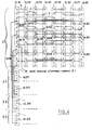
- the nodes of processors have the general reference numeral 1 and, according to one aspect of the invention, the set of nodes 1 is divided according to super nodes with the numerical reference general 2.
- the set illustrated has four super knots 2 each comprising eight nodes 1.
- the general reference is associated with a particular reference.
- each node 1 has a special reference identifying it on the one hand by the super node to which it belongs (first digit of the particular reference) and on the other hand by its number order in the super node (second digit of the reference particular). So the first node of the first super node bears the complete reference 1.11, the second node of the first super node carries the full reference 1.12, the third node of the first super node carries the complete reference 1.13 ....
- the first node of the second super node 2.2 carries the complete reference 1.21, the second node of the second super node 2.2 carries the complete reference 1.22 ).
- Each super node 2 is divided into two subsets 3 marked by a dashed line for the super node 2.1.
- the first subset the super node 2.1 which includes the nodes 1.11, 1.12, 1.13 and 1.14, has the full reference 3.11 and the second subset which includes nodes 1.15, 1.16, 1.17 and 1.18, bears the full reference 3.12.
- the nodes are connected them to each other by series 4 links illustrated by a thick solid line when using a serial link double and with a thin continuous line when it is a simple serial link.
- a simple serial link within the meaning of the present description is usually consisting of two shielded differential pairs forming a single logical link and represented as such by a single line in the figures.
- nodes of a subset 3 are interconnected by double serial links and are connected to the nodes of an adjacent subset of the same super node 2 by simple serial links.
- node 1.11 is connected by double serial links to each of the nodes 1.12, 1.13 and 1.14 of the same subset 3.11, and by simple connections to nodes 1.15, 1.16, 1.17 and 1.18 of the subset adjacent 3.12 of the same super node 2.1.
- the super nodes 2 are linked in pairs by serial links duplicates associating each node of a super node with a node correspondent of another super knot. So the two super nodes 2.1 and 2.2 are paired by establishing a connection double between node 1.11 and node 1.21, between node 1.12 and the node 1.22 altogether these double bonds not being marked in the figure only for the extreme lateral knots of the schematic representation illustrated and being marked only by a thick line start for the others knots. Similarly, super nodes 2.3 and 2.4 are paired by double links respectively connecting the node 1.31 at node 1.41, node 1.32 at node 1.42 ....
- each pair of associated super nodes is linked to another pair of super nodes associated by simple serial links connecting each node of a pair to two matching nodes from the other pair.
- knot 1.11 is connected by a simple serial link to node 1.31 and at node 1.41 ...
- node 1.21 is also connected by a simple serial link at node 1.31 and at node 1.41 .... same as before for double bonds between two super paired nodes, simple links between two pairs super knots have been marked in the figure only for the extreme lateral nodes, the other simple links being only marked by a fine line start from of each node.
- the computer assembly according to the invention further comprises a super node 5 of input / output devices bearing the reference general 6, each input / output member 6 being connected by a serial link 4 to a corresponding node of each super knots.
- the organs input / output respectively have the references complete digital 6.1, 6.2 .
- the input / output device 6.1 is connected by simple serial links 4 to the nodes 1.11, 1.21, 1.31 and 1.41; the input / output device 6.2 is connected to nodes 1.12, 1.22, 1.32 and 1.42 .... and, within super node 5, the input / output devices are also linked together by a simple serial link 7.
- FIG. 2 schematically illustrates the structure of an embodiment of a node according to the invention.
- each node comprises four processors with general reference 8 and one particular reference to identify in relation to node to which it belongs (first two digits of the particular reference), and by its serial number in the node (last digit of the particular reference).
- Figure 2 illustrates the structure of node 1.11 and, to identify each of the processors in relationship with this node, these bear the references complete numeric numbers 8.111.8.112, 8.113 and 8.114.
- full processor references will be 8.431, 8.432, 8.433 and 8.434.
- Each processor is associated with a private cache with the general reference 9, and respectively the complete references 9.111, 9.112, 9.113 and 9.114.
- cache is commonly used to designate a memory containing information which is copies of information originally held at a address of the general memory of the computer system so that a particular instruction processor can use this information faster than if he had to systematically question the general memory at every time he executes an instruction implementing this information.
- the private cache term will be used for a cache to which a instruction processor is directly connected.
- Each private caches 9 is connected to two local buses carrying the general reference 10 and, respectively, the references 10.111 and 10.112.
- local memory is used for a memory comprising a part of general memory, i.e. part of original information accessible by all microprocessors.
- shared cache is used to designate a memory that contains copies of information contained in the local memories of the other nodes of the computer system and which is intended to be used by the different processors of the node in which the cache shared is willing.
- private caches, shared caches and local memories include management processors that were not represented on the figures.
- Each private cache is a level 1 memory higher in the hierarchy for a node considered, each shared cache is a second level memory of the hierarchy for the node considered and each local memory is so a second level memory of the hierarchy for the considered node and third level of the hierarchy for the other nodes.
- the part of general memory associated with the node has been subdivided in two local memories, the even local memory 11,111 which contains the information at even addresses and that is associated with the even local bus 10.111, and the local memory odd 11,112 which contains information held at odd addresses and which is connected to the odd local bus 1.112.
- the shared cache associated with the node has been divided into an even shared cache 12,111 containing copies even address information, and connected to the even local bus 10.111, and the odd shared cache 12.112 containing copies of information to odd addresses and connected to the bus odd local 10.112.
- Each local memory and each cache shared is connected to a network bus 13 providing a link parallel, respectively 13.111 for the even network bus and 13.112 for the odd network bus.
- the network buses are linked to serial links 14, respectively 14.111, 14.112, 14.113 and 14.114 in the illustrated embodiment.
- the controllers of serial links 14 provide an interface between the buses networks and the serial links 4 which provide the links between the nodes.
- the link controllers series 14 are connected to each of the network buses 13.
- each node is associated with other nodes, and to the input / output organs by a total of 15 serial links.
- Network buses could be linked to serial links via an interface with a single serial link controller. However, for reasons technological, the power consumed would be too large and would cause an unacceptable heating of this interface. This is the reason why the interface between network buses and serial links has been subdivided into four serial link controllers.
- each bus parallel type whether local buses or buses networks is equipped with six sockets, which ensures a sufficient message throughput without unduly increasing the complexity of the protocols for transmitting these messages.
- Figure 4 illustrates the distribution of links between the serial link controllers of the same super node and with the serial link controllers of the other super nodes with which a super node is associated.
- the lines between serial link controllers and buses networks were not represented.
- the distribution of the serial links between the serial link controllers of the first super node 2.1 and, for the connections with the other super nodes we have represented only the distribution of serial links between the node 1.11 and the corresponding serial link controllers other super knots.
- each link controller series is represented by a dashed rectangle and the connections of a serial link 4 with a serial links are represented by a solid line for each single serial link.
- the first controller serial links of node 1.11 carries the complete reference 14.111 while the first serial link controller of the node 1.12 carries the complete reference 14.121 whereas the second 1.11 serial link controller carries the reference 14.112, the second link controller 1.12 node series carries the full reference 1.122 ....
- the double serial link connecting node 1.11 with node 1.12 is illustrated by a simple serial link connecting the serial link controller 14.111 and the serial link controller 14.121 and a simple serial link connecting the serial link controller 14.112 and the serial link controller 14.122;
- the double serial link connecting node 1.11 to node 1.14 is illustrated by a simple link connecting the controller serial links 14.113 to the serial link controller 14.143 and a simple serial link connecting the controller 14.114 serial links to the serial link controller 14,144;
- the double serial link connecting node 1.11 and the node 1.21 is illustrated by a simple serial link connecting the serial link controller 14.111 and the 14.211 serial links, and a single serial link connecting the serial link controller 14.114 to the serial links 14.214.
- the simple serial link connecting the node 1.11 at node 1.31 is illustrated by the serial link simple connecting the serial link controller 14.113 to 14.313 serial link controller, and the serial link simple connecting node 1.11 to node 1.41 is illustrated by the simple serial link connecting the link controller 14.112 to the 14.412 serial link controller.
- the serial link controller 14.113 includes in addition to a terminal connected to the serial link controller the input device 6.1, and which has not been shown on the figure.
- the serial link controller 14.114 has a unassigned terminal which can, if necessary, be used to ensure a double serial link between node 1.11 and the organ input / output 6.1.
- connections thus established allow to go from any node to another node using only two serial links.
- node 1.11 to node 1.33 using first one of the serial links from node 1.11 to node 1.13 then the serial link connecting node 1.13 to node 1.33.
- node 1.35 to node 1.22 using the serial link from node 1.35 to node 1.32 then the link series from node 1.32 to node 1.22.
- this property is also obtained for the binding of any of input / output devices with any of the nodes.
- an input / output device is not usually intended to work with all of nodes and we can therefore save links by removing those which connect the input / output members together.
- FIG. 3 partially illustrates a alternative embodiment of the knot illustrated in FIG. 2 allowing to double the number of processors in the node without increasing the number of sockets on local buses and without otherwise changing the links between the nodes.
- each of the processors and the private cache associated with it is replaced by two processors each associated with a private cache.
- Figure 3 illustrates the splitting of the processor 8.111 in FIG. 2, identical duplication being of course carried out for other processors on the same node so as not to complicate improperly handling messages with the node.
- the 8.111 processor is therefore replaced by an 8.1111 processor and a processor 8.1112 respectively connected to a cache private 9.1111 and a private cache 9.1112.
- Each private cache is connected to two interfaces 15 for connection to buses premises, a 15.1111 peer bus interface which is connected to the bus local even 10.111 and an odd bus interface 15.1112 which is connected to the odd local bus 10.112.
- the node includes as before 4 processors 8.111, 8.112, 8.113 and 8.114 respectively linked to private caches 9.111, 9.112, 9.113 and 9.114 associated with a single local bus 10.11 which is itself linked to a single local memory 11.11 and a single shared cache 12.11. Local memory and cache shared are linked to a single network bus 13.11.
- the local bus only serves as previously that the transmission of the necessary messages to the processors of the node to take the information contained in local memory or copies of information contained in the shared cache while the network bus is used the transmission of messages intended to update information from local memory or shared cache, or bring the copies requested by it to the shared cache of information contained in the local memories of other nodes, or to take from the local memory of the node information requested by others' shared caches knots.
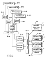
- the embodiment illustrated by figure 5 corresponds to a configuration less than the maximum configuration, i.e. a configuration with a number of nodes lower than number of nodes shown in Figure 1 so that the number of serial links has been reduced to twelve and the number of serial link controllers has been reduced to three.
- the number of network bus sockets used by local memory, shared cache and controllers serial links is only five so it's then possible to directly connect the input / output device 6.1 on the network bus 13.11.
- the controller 6.1 input / output device serial links (not shown in the figure) is only used to manage the messages on series 7 links bringing together the organs between them.
- FIG. 6 illustrates an even more configuration simple comprising only two nodes 1.1 and 1.2 materialized by mixed line frames in this figure.
- each node has 4 processors, respectively referenced 8.11, 8.12, 8.13 and 8.14 for node 1.1; and 8.21, 8.22, 8.23 and 8.24 for node 1.2.
- Processors are respectively connected to private caches 9.12, 9.12 .... and 9.21, 9.22 .... themselves connected to two buses premises, respectively 10.1 and 10.2.
- Local buses are each linked to a local memory, respectively 11.1 and 11.2, and to a shared cache, 12.1 and 12.2.
- each node also has a member input / output, respectively 6.1 and 6.2.
- the number of nodes or the number of super nodes is not determined from critically and the overall structure of the whole computing according to the invention or the structure of the nodes can be advantageously adapted according to the configurations to realize that we will preferably seek to balance in using the original structural aspects of the invention.
- a computer assembly having a scalable configuration from 1 to 8 processors we will use preferably the structure described in relation to FIG. 6, by reducing this to a single node for a configuration ranging from 1 to 4 processors.
- a computer system having a scalable configuration comprising from 4 to 32 processors we will preferably produce a structure reproducing the structure of a super node according to the invention.
- serial links corresponding to the maximum configuration preferably installed in the basic structure of the machine to allow easy modification of the configuration, especially for modify the connection connections in the event failure of a serial link or to change the configuration, both in an increasing direction than the decrease in the number of microprocessors, without it it is necessary to modify the interconnections.
Landscapes
- Engineering & Computer Science (AREA)
- Computer Hardware Design (AREA)
- Theoretical Computer Science (AREA)
- Physics & Mathematics (AREA)
- General Engineering & Computer Science (AREA)
- General Physics & Mathematics (AREA)
- Computing Systems (AREA)
- Mathematical Physics (AREA)
- Software Systems (AREA)
- Multi Processors (AREA)
Claims (9)
- Datenverarbeitungssystem mit gemeinsam genutztem Speicher, das eine bis zu einer Maximalkonfiguration erweiterbare Konfiguration aufweist und in der Maximalkonfiguration eine vorgegebene Anzahl von Prozessoren (8.111 ... 8.114) enthält, die in Untereinheiten (3.11, 3.12) von Knoten (1.11 ... 1.48) gruppiert sind, wobei jede Untereinheit eine kritische Größe in bezug auf den Nachrichtendurchsatz zwischen Knoten aufweist, wobei das System Verbindungsmittel enthält, die doppelte Serienverbindungen für die Verbindung der Knoten jeder Untereinheit miteinander für die Nachrichtenübertragung sowie einfache Serienverbindungen für die Verbindung der Knoten einer Untereinheit mit den Knoten anderer Untereinheiten für die Nachrichtenübertragung umfassen.
- System nach Anspruch 1, in dem die Maximalkonfiguration in Oberknoten unterteilt ist, die jeweils zwei Untereinheiten enthalten.
- System nach Anspruch 2, in dem die Oberknoten paarweise verbunden sind (2.1, 2.2; 2.3, 2.4), wobei jeder Knoten eines Oberknotens mit einem Knoten eines anderen Oberknotens verbunden ist, um ein Paar entsprechender Knoten zu bilden, und die Verbindungsmittel doppelte Serienverbindungen enthalten, um die Paare entsprechender Knoten zu verbinden.
- System nach Anspruch 3, in dem die Paare entsprechender Knoten in einem Paar Oberknoten den Paaren entsprechender Knoten in einem anderen Paar Oberknoten entsprechen und die Verbindungsmittel einfache Serienverbindungen enthalten, um jeden Knoten jedes der Paare entsprechender Knoten in einem Oberknotenpaar mit zwei Knoten des Paares entsprechender Knoten des anderen Oberknotenpaars zu verbinden.
- System nach einem der Ansprüche 3 oder 4, in dem die Knoten jeweilige Positionen (1.11) in einem der Oberknoten (2.1) und entsprechende Positionen (1.31) mit den Knoten eines anderen der Oberknoten (2.3) besitzen und der Nachrichtenaustausch zwischen einem Knoten (1.11) eines Oberknotens (2.1) mit einem anderen Knoten (1.33) des anderen Oberknotens (2.3) über den Knoten (1.13) im Oberknoten (2.1) ausgeführt wird, der dem anderen Knoten (1.33) entspricht.
- System nach einem der Ansprüche 1 bis 5, in dem die Verbindungsmittel Serienverbindungs-Steuereinrichtungen enthalten, die miteinander über wenigstens einen Bus im entsprechenden Knoten verbunden sind, wobei die Serienverbindungs-Steuereinrichtungen eine Schnittstelle zwischen dem Bus und den die Verbindungen zwischen Knoten sicherstellenden Serienverbindungen sicherstellen.
- System nach einem der Ansprüche 1 bis 6, in dem wenigstens ein Teil der Knoten über einfache Serienverbindungen mit Eingangs-/Ausgangselementen verbunden ist.
- System nach Anspruch 7, in dem die Eingangs-/Ausgangs-Elemente mit Hilfe von jeweiligen einfachen Serienverbindungen miteinander verbunden sind.
- System nach einem der Ansprüche 1 bis 8, in dem die Verbindungsmittel, die der Maximalkonfiguratiton entsprechen, in der Grundkonfiguration einer Maschine installiert sind.
Applications Claiming Priority (2)
| Application Number | Priority Date | Filing Date | Title |
|---|---|---|---|
| FR9308710A FR2707777B1 (fr) | 1993-07-15 | 1993-07-15 | Ensemble informatique à mémoire partagée. |
| FR9308710 | 1993-07-15 |
Publications (2)
| Publication Number | Publication Date |
|---|---|
| EP0634724A1 EP0634724A1 (de) | 1995-01-18 |
| EP0634724B1 true EP0634724B1 (de) | 1999-10-27 |
Family
ID=9449276
Family Applications (1)
| Application Number | Title | Priority Date | Filing Date |
|---|---|---|---|
| EP94401596A Expired - Lifetime EP0634724B1 (de) | 1993-07-15 | 1994-07-11 | Verarbeitungssystem mit gemeinschaftlichem Speicher |
Country Status (5)
| Country | Link |
|---|---|
| US (1) | US5644716A (de) |
| EP (1) | EP0634724B1 (de) |
| JP (1) | JP2905695B2 (de) |
| DE (1) | DE69421334T2 (de) |
| FR (1) | FR2707777B1 (de) |
Families Citing this family (5)
| Publication number | Priority date | Publication date | Assignee | Title |
|---|---|---|---|---|
| FR2737031B1 (fr) * | 1995-07-21 | 1997-08-14 | Bull Sa | Procede de transfert de donnees dans un systeme informatique multinodal |
| FR2754925B1 (fr) * | 1996-10-18 | 1998-11-20 | Bull Sa | Operation atomique sur memoire distante et dispositif permettant d'effectuer cette operation |
| DE19756591B4 (de) * | 1997-12-18 | 2004-03-04 | Sp3D Chip Design Gmbh | Vorrichtung zum hierarchischen Verbinden einer Mehrzahl von Funktionseinheiten in einem Prozessor |
| US7380102B2 (en) * | 2005-09-27 | 2008-05-27 | International Business Machines Corporation | Communication link control among inter-coupled multiple processing units in a node to respective units in another node for request broadcasting and combined response |
| US8775516B2 (en) * | 2010-03-26 | 2014-07-08 | Seiko Epson Corporation | Projector system and connection establishment method |
Family Cites Families (18)
| Publication number | Priority date | Publication date | Assignee | Title |
|---|---|---|---|---|
| US4445174A (en) * | 1981-03-31 | 1984-04-24 | International Business Machines Corporation | Multiprocessing system including a shared cache |
| US4644496A (en) * | 1983-01-11 | 1987-02-17 | Iowa State University Research Foundation, Inc. | Apparatus, methods, and systems for computer information transfer |
| JPS59218532A (ja) * | 1983-05-27 | 1984-12-08 | Hitachi Ltd | バス接続方式 |
| US4755930A (en) * | 1985-06-27 | 1988-07-05 | Encore Computer Corporation | Hierarchical cache memory system and method |
| US5165018A (en) * | 1987-01-05 | 1992-11-17 | Motorola, Inc. | Self-configuration of nodes in a distributed message-based operating system |
| AU598101B2 (en) * | 1987-02-27 | 1990-06-14 | Honeywell Bull Inc. | Shared memory controller arrangement |
| FR2618625B1 (fr) * | 1987-07-24 | 1989-11-24 | Labo Electronique Physique | Dispositif d'amelioration du decodage de signaux numeriques lors de transmissions en modulation de frequence |
| JPH01144154A (ja) * | 1987-11-30 | 1989-06-06 | Sharp Corp | 階層構造による分散処理装置 |
| EP0343567A3 (de) * | 1988-05-25 | 1991-01-09 | Hitachi, Ltd. | Mehrprozessoranordnung und Cache-Speichervorrichtung zur Verwendung in dieser Anordnung |
| JPH0680499B2 (ja) * | 1989-01-13 | 1994-10-12 | インターナショナル・ビジネス・マシーンズ・コーポレーション | マルチプロセッサ・システムのキャッシュ制御システムおよび方法 |
| JPH0721781B2 (ja) * | 1989-03-13 | 1995-03-08 | インターナショナル・ビジネス・マシーンズ・コーポレーション | マルチプロセツサ・システム |
| JPH02253356A (ja) * | 1989-03-28 | 1990-10-12 | Toshiba Corp | 階層キャッシュメモリ装置とその制御方式 |
| US5136700A (en) * | 1989-12-22 | 1992-08-04 | Digital Equipment Corporation | Apparatus and method for reducing interference in two-level cache memories |
| JPH061463B2 (ja) * | 1990-01-16 | 1994-01-05 | インターナショナル・ビジネス・マシーンズ・コーポレーション | マルチプロセッサ・システムおよびそのプライベート・キャッシュ制御方法 |
| US5161156A (en) * | 1990-02-02 | 1992-11-03 | International Business Machines Corporation | Multiprocessing packet switching connection system having provision for error correction and recovery |
| JPH0625984B2 (ja) * | 1990-02-20 | 1994-04-06 | インターナシヨナル・ビジネス・マシーンズ・コーポレーシヨン | マルチプロセツサ・システム |
| US5291442A (en) * | 1990-10-31 | 1994-03-01 | International Business Machines Corporation | Method and apparatus for dynamic cache line sectoring in multiprocessor systems |
| US5303362A (en) * | 1991-03-20 | 1994-04-12 | Digital Equipment Corporation | Coupled memory multiprocessor computer system including cache coherency management protocols |
-
1993
- 1993-07-15 FR FR9308710A patent/FR2707777B1/fr not_active Expired - Fee Related
-
1994
- 1994-07-11 EP EP94401596A patent/EP0634724B1/de not_active Expired - Lifetime
- 1994-07-11 DE DE69421334T patent/DE69421334T2/de not_active Expired - Lifetime
- 1994-07-12 JP JP6160156A patent/JP2905695B2/ja not_active Expired - Lifetime
- 1994-07-15 US US08/275,377 patent/US5644716A/en not_active Expired - Lifetime
Also Published As
| Publication number | Publication date |
|---|---|
| EP0634724A1 (de) | 1995-01-18 |
| DE69421334T2 (de) | 2000-02-10 |
| JPH0756875A (ja) | 1995-03-03 |
| DE69421334D1 (de) | 1999-12-02 |
| US5644716A (en) | 1997-07-01 |
| FR2707777B1 (fr) | 1995-08-18 |
| FR2707777A1 (fr) | 1995-01-20 |
| JP2905695B2 (ja) | 1999-06-14 |
Similar Documents
| Publication | Publication Date | Title |
|---|---|---|
| EP0597028B1 (de) | Vorrichtung mit paralleler prozessor matrix | |
| EP0636988B1 (de) | Kohärenter Datenaustausch, Verwaltungsverfahren zwischen den Stufen einer mindestens dreistufigen Speicherhierarchie | |
| EP0616479B1 (de) | Verfahren zur Neukonfigurierung eines Maschennetzwerks | |
| CA2725292A1 (fr) | Systeme et procede de simulation ou de test exploitant des donnees issues de ports de surveillance | |
| CA2042952C (fr) | Reseau de commutation a trajets multiples et a auto-acheminement pour la commutation de cellules a multiplexage temporel asynchrone avec signalisation de disponibilite | |
| EP0634725B1 (de) | Prozessorenknoten | |
| EP0646875B1 (de) | Verfahren und System von Zwischenverbindungen zur Verwaltung von Meldungen in einem Prozessorennetzwerk mit paralleler Struktur | |
| EP0634724A1 (de) | Verarbeitungssystem mit gemeinschaftlichem Speicher | |
| EP2577920B1 (de) | Verfahren des pseudodynamischen routing in einem cluster mit statischen kommunikationslinks und computerprogramm, das dieses verfahren implementiert | |
| EP0689320A1 (de) | Verfahren und Anlagen für Leitweglenkung von Datenpaketen in einem verteilten Netzwerk | |
| FR2945647A1 (fr) | Methode d'optimisation d'une plateforme avionique | |
| FR2742894A1 (fr) | Systeme d'echange d'informations entre plusieurs operateurs | |
| EP1493083A2 (de) | Umkonfigurierbares steuersystem auf der basis einer hardwareimplementierung von petri-graphen | |
| CA2566067C (fr) | Procede et dispositif de gestion d'un bus | |
| EP0113272A1 (de) | Modulares Kommunikationsknotenkoppelfeld | |
| FR2779844A1 (fr) | Structure d'interconnexion entre organes adressables d'un microcalculateur, notamment pour dispositif medical implantable actif tel que stimulateur ou defibrillateur cardiaque | |
| FR2655750A1 (fr) | Systeme de traitement de donnees multiprocesseur a bus actif reconfigurable. | |
| FR2857472A1 (fr) | Systeme de gestion distribuee des ressources informatiques et des calculs | |
| FR2773239A1 (fr) | Configuration d'un systeme informatique multinodal | |
| FR2863427A1 (fr) | Construction d'une base de donnees des connexions physiques d'un reseau de transmission d'informations | |
| WO1998040836A1 (fr) | Equipement informatique forme d'une pluralite de modules interconnectes et procede pour l'optimisation de telles ressources informatiques | |
| FR2642252A1 (fr) | Unite d'interconnexion entre circuits, notamment du type crossbar procede de mise en oeuvre d'une unite d'interconnexion entre circuits, et utilisations d'une unite d'interconnexion entre circuits | |
| EP0797153A1 (de) | Informationsverarbeitungsvorrichtung mit mehreren parallelen Prozessoren | |
| FR2807541A1 (fr) | Systeme d'information pour la construction, la gestion et la supervision dans un reseau de transport d'un faisceau disposant de ressources entre deux noeuds et noeud d'acces a un reseau de transport | |
| FR2938997A1 (fr) | Mecanisme de tolerance aux fautes optimise pour reseau pair-a-pair |
Legal Events
| Date | Code | Title | Description |
|---|---|---|---|
| PUAI | Public reference made under article 153(3) epc to a published international application that has entered the european phase |
Free format text: ORIGINAL CODE: 0009012 |
|
| AK | Designated contracting states |
Kind code of ref document: A1 Designated state(s): DE FR GB IT |
|
| 17P | Request for examination filed |
Effective date: 19950213 |
|
| 17Q | First examination report despatched |
Effective date: 19980525 |
|
| GRAG | Despatch of communication of intention to grant |
Free format text: ORIGINAL CODE: EPIDOS AGRA |
|
| GRAG | Despatch of communication of intention to grant |
Free format text: ORIGINAL CODE: EPIDOS AGRA |
|
| GRAH | Despatch of communication of intention to grant a patent |
Free format text: ORIGINAL CODE: EPIDOS IGRA |
|
| GRAH | Despatch of communication of intention to grant a patent |
Free format text: ORIGINAL CODE: EPIDOS IGRA |
|
| GRAA | (expected) grant |
Free format text: ORIGINAL CODE: 0009210 |
|
| AK | Designated contracting states |
Kind code of ref document: B1 Designated state(s): DE FR GB IT |
|
| GBT | Gb: translation of ep patent filed (gb section 77(6)(a)/1977) |
Effective date: 19991027 |
|
| REF | Corresponds to: |
Ref document number: 69421334 Country of ref document: DE Date of ref document: 19991202 |
|
| ITF | It: translation for a ep patent filed | ||
| PLBE | No opposition filed within time limit |
Free format text: ORIGINAL CODE: 0009261 |
|
| STAA | Information on the status of an ep patent application or granted ep patent |
Free format text: STATUS: NO OPPOSITION FILED WITHIN TIME LIMIT |
|
| 26N | No opposition filed | ||
| REG | Reference to a national code |
Ref country code: GB Ref legal event code: IF02 |
|
| PGFP | Annual fee paid to national office [announced via postgrant information from national office to epo] |
Ref country code: GB Payment date: 20130626 Year of fee payment: 20 |
|
| PGFP | Annual fee paid to national office [announced via postgrant information from national office to epo] |
Ref country code: DE Payment date: 20130621 Year of fee payment: 20 |
|
| PGFP | Annual fee paid to national office [announced via postgrant information from national office to epo] |
Ref country code: FR Payment date: 20130722 Year of fee payment: 20 |
|
| PGFP | Annual fee paid to national office [announced via postgrant information from national office to epo] |
Ref country code: IT Payment date: 20130628 Year of fee payment: 20 |
|
| REG | Reference to a national code |
Ref country code: DE Ref legal event code: R071 Ref document number: 69421334 Country of ref document: DE |
|
| REG | Reference to a national code |
Ref country code: GB Ref legal event code: PE20 Expiry date: 20140710 |
|
| PG25 | Lapsed in a contracting state [announced via postgrant information from national office to epo] |
Ref country code: DE Free format text: LAPSE BECAUSE OF EXPIRATION OF PROTECTION Effective date: 20140712 |
|
| PG25 | Lapsed in a contracting state [announced via postgrant information from national office to epo] |
Ref country code: GB Free format text: LAPSE BECAUSE OF EXPIRATION OF PROTECTION Effective date: 20140710 |