EP0635312B1 - Atomiseur a ultrasons - Google Patents
Atomiseur a ultrasons Download PDFInfo
- Publication number
- EP0635312B1 EP0635312B1 EP93908070A EP93908070A EP0635312B1 EP 0635312 B1 EP0635312 B1 EP 0635312B1 EP 93908070 A EP93908070 A EP 93908070A EP 93908070 A EP93908070 A EP 93908070A EP 0635312 B1 EP0635312 B1 EP 0635312B1
- Authority
- EP
- European Patent Office
- Prior art keywords
- mesh plate
- pump shaft
- ultrasonic
- pump
- ultrasonic atomizer
- Prior art date
- Legal status (The legal status is an assumption and is not a legal conclusion. Google has not performed a legal analysis and makes no representation as to the accuracy of the status listed.)
- Expired - Lifetime
Links
- 239000007788 liquid Substances 0.000 claims abstract description 90
- 230000006835 compression Effects 0.000 claims abstract description 19
- 238000007906 compression Methods 0.000 claims abstract description 19
- 239000007921 spray Substances 0.000 claims abstract description 10
- 125000006850 spacer group Chemical group 0.000 claims description 8
- 230000002093 peripheral effect Effects 0.000 claims description 6
- 230000015572 biosynthetic process Effects 0.000 claims description 4
- 230000004044 response Effects 0.000 claims description 2
- 241000237519 Bivalvia Species 0.000 claims 1
- 235000020639 clam Nutrition 0.000 claims 1
- 238000005507 spraying Methods 0.000 description 20
- 230000007704 transition Effects 0.000 description 17
- 238000000889 atomisation Methods 0.000 description 8
- 230000009471 action Effects 0.000 description 7
- 239000003814 drug Substances 0.000 description 7
- 238000000034 method Methods 0.000 description 7
- 239000002184 metal Substances 0.000 description 6
- 238000005086 pumping Methods 0.000 description 5
- 238000010276 construction Methods 0.000 description 4
- 230000029058 respiratory gaseous exchange Effects 0.000 description 4
- 230000007423 decrease Effects 0.000 description 3
- 230000000694 effects Effects 0.000 description 3
- 238000005323 electroforming Methods 0.000 description 3
- 238000007689 inspection Methods 0.000 description 3
- 230000008569 process Effects 0.000 description 3
- 238000012545 processing Methods 0.000 description 3
- XLYOFNOQVPJJNP-UHFFFAOYSA-N water Substances O XLYOFNOQVPJJNP-UHFFFAOYSA-N 0.000 description 3
- 238000004140 cleaning Methods 0.000 description 2
- 230000013011 mating Effects 0.000 description 2
- 238000001259 photo etching Methods 0.000 description 2
- FAPWRFPIFSIZLT-UHFFFAOYSA-M Sodium chloride Chemical compound [Na+].[Cl-] FAPWRFPIFSIZLT-UHFFFAOYSA-M 0.000 description 1
- 230000008859 change Effects 0.000 description 1
- 230000003247 decreasing effect Effects 0.000 description 1
- 230000002939 deleterious effect Effects 0.000 description 1
- 238000001514 detection method Methods 0.000 description 1
- 238000010586 diagram Methods 0.000 description 1
- 229940079593 drug Drugs 0.000 description 1
- 230000003670 easy-to-clean Effects 0.000 description 1
- 230000001747 exhibiting effect Effects 0.000 description 1
- 238000002474 experimental method Methods 0.000 description 1
- 238000001746 injection moulding Methods 0.000 description 1
- WABPQHHGFIMREM-UHFFFAOYSA-N lead(0) Chemical compound [Pb] WABPQHHGFIMREM-UHFFFAOYSA-N 0.000 description 1
- 238000004519 manufacturing process Methods 0.000 description 1
- 239000000463 material Substances 0.000 description 1
- 230000004048 modification Effects 0.000 description 1
- 238000012986 modification Methods 0.000 description 1
- 239000002504 physiological saline solution Substances 0.000 description 1
- 239000004033 plastic Substances 0.000 description 1
- 239000002985 plastic film Substances 0.000 description 1
- 229920006255 plastic film Polymers 0.000 description 1
- 239000011780 sodium chloride Substances 0.000 description 1
- 239000000243 solution Substances 0.000 description 1
- 239000000725 suspension Substances 0.000 description 1
- 238000012360 testing method Methods 0.000 description 1
- 239000012780 transparent material Substances 0.000 description 1
- 239000002699 waste material Substances 0.000 description 1
- 238000003466 welding Methods 0.000 description 1
Images









Classifications
-
- B—PERFORMING OPERATIONS; TRANSPORTING
- B05—SPRAYING OR ATOMISING IN GENERAL; APPLYING FLUENT MATERIALS TO SURFACES, IN GENERAL
- B05B—SPRAYING APPARATUS; ATOMISING APPARATUS; NOZZLES
- B05B17/00—Apparatus for spraying or atomising liquids or other fluent materials, not covered by the preceding groups
- B05B17/04—Apparatus for spraying or atomising liquids or other fluent materials, not covered by the preceding groups operating with special methods
- B05B17/06—Apparatus for spraying or atomising liquids or other fluent materials, not covered by the preceding groups operating with special methods using ultrasonic or other kinds of vibrations
- B05B17/0607—Apparatus for spraying or atomising liquids or other fluent materials, not covered by the preceding groups operating with special methods using ultrasonic or other kinds of vibrations generated by electrical means, e.g. piezoelectric transducers
- B05B17/0638—Apparatus for spraying or atomising liquids or other fluent materials, not covered by the preceding groups operating with special methods using ultrasonic or other kinds of vibrations generated by electrical means, e.g. piezoelectric transducers spray being produced by discharging the liquid or other fluent material through a plate comprising a plurality of orifices
-
- A—HUMAN NECESSITIES
- A61—MEDICAL OR VETERINARY SCIENCE; HYGIENE
- A61M—DEVICES FOR INTRODUCING MEDIA INTO, OR ONTO, THE BODY; DEVICES FOR TRANSDUCING BODY MEDIA OR FOR TAKING MEDIA FROM THE BODY; DEVICES FOR PRODUCING OR ENDING SLEEP OR STUPOR
- A61M15/00—Inhalators
- A61M15/0085—Inhalators using ultrasonics
-
- B—PERFORMING OPERATIONS; TRANSPORTING
- B05—SPRAYING OR ATOMISING IN GENERAL; APPLYING FLUENT MATERIALS TO SURFACES, IN GENERAL
- B05B—SPRAYING APPARATUS; ATOMISING APPARATUS; NOZZLES
- B05B17/00—Apparatus for spraying or atomising liquids or other fluent materials, not covered by the preceding groups
- B05B17/04—Apparatus for spraying or atomising liquids or other fluent materials, not covered by the preceding groups operating with special methods
- B05B17/06—Apparatus for spraying or atomising liquids or other fluent materials, not covered by the preceding groups operating with special methods using ultrasonic or other kinds of vibrations
- B05B17/0607—Apparatus for spraying or atomising liquids or other fluent materials, not covered by the preceding groups operating with special methods using ultrasonic or other kinds of vibrations generated by electrical means, e.g. piezoelectric transducers
- B05B17/0623—Apparatus for spraying or atomising liquids or other fluent materials, not covered by the preceding groups operating with special methods using ultrasonic or other kinds of vibrations generated by electrical means, e.g. piezoelectric transducers coupled with a vibrating horn
-
- B—PERFORMING OPERATIONS; TRANSPORTING
- B05—SPRAYING OR ATOMISING IN GENERAL; APPLYING FLUENT MATERIALS TO SURFACES, IN GENERAL
- B05B—SPRAYING APPARATUS; ATOMISING APPARATUS; NOZZLES
- B05B17/00—Apparatus for spraying or atomising liquids or other fluent materials, not covered by the preceding groups
- B05B17/04—Apparatus for spraying or atomising liquids or other fluent materials, not covered by the preceding groups operating with special methods
- B05B17/06—Apparatus for spraying or atomising liquids or other fluent materials, not covered by the preceding groups operating with special methods using ultrasonic or other kinds of vibrations
- B05B17/0607—Apparatus for spraying or atomising liquids or other fluent materials, not covered by the preceding groups operating with special methods using ultrasonic or other kinds of vibrations generated by electrical means, e.g. piezoelectric transducers
- B05B17/0623—Apparatus for spraying or atomising liquids or other fluent materials, not covered by the preceding groups operating with special methods using ultrasonic or other kinds of vibrations generated by electrical means, e.g. piezoelectric transducers coupled with a vibrating horn
- B05B17/063—Apparatus for spraying or atomising liquids or other fluent materials, not covered by the preceding groups operating with special methods using ultrasonic or other kinds of vibrations generated by electrical means, e.g. piezoelectric transducers coupled with a vibrating horn having an internal channel for supplying the liquid or other fluent material
-
- B—PERFORMING OPERATIONS; TRANSPORTING
- B05—SPRAYING OR ATOMISING IN GENERAL; APPLYING FLUENT MATERIALS TO SURFACES, IN GENERAL
- B05B—SPRAYING APPARATUS; ATOMISING APPARATUS; NOZZLES
- B05B9/00—Spraying apparatus for discharge of liquids or other fluent material, without essentially mixing with gas or vapour
- B05B9/03—Spraying apparatus for discharge of liquids or other fluent material, without essentially mixing with gas or vapour characterised by means for supplying liquid or other fluent material
-
- A—HUMAN NECESSITIES
- A61—MEDICAL OR VETERINARY SCIENCE; HYGIENE
- A61M—DEVICES FOR INTRODUCING MEDIA INTO, OR ONTO, THE BODY; DEVICES FOR TRANSDUCING BODY MEDIA OR FOR TAKING MEDIA FROM THE BODY; DEVICES FOR PRODUCING OR ENDING SLEEP OR STUPOR
- A61M15/00—Inhalators
- A61M15/0065—Inhalators with dosage or measuring devices
- A61M15/0068—Indicating or counting the number of dispensed doses or of remaining doses
- A61M15/0083—Timers
Definitions
- This invention relates to an ultrasonic atomizer for pumping up a liquid from a liquid vessel by an ultrasonic pump and atomizing the liquid by passing it through a mesh plate formed to have multiplicity of minute holes, an ultrasonic inhaler serving as one application of the ultrasonic atomizer, and a method of controlling the operation of the inhaler.
- a known example of an ultrasonic atomizer of this type is described in the specification of JP-U-3-15674.
- the atomizer described in this literature is characterized by use of a mesh plate having tapered minute holes which flare from one side of the plate toward the other.
- the mesh plate is arranged in such a manner that the side in which the minute holes have the openings of larger diameter opposes the upper end face of the pump shaft of an ultrasonic pump, and such that a minute gap is produced between the mesh plate and the upper end face of the pump shaft.
- an ultrasonic atomizer it is important to achieve balance between the amount of liquid pumped by the ultrasonic pump and the amount of atomization produced by the mesh plate.
- the amount of liquid pumped tends to be larger than the amount of liquid atomized.
- the liquid that is not atomized flows down from the gap to the upper portion (the horn) of the pump shaft and becomes a load on ultrasonic vibration at the horn. This causes an unstable spraying operation and can lead to cessation of operation in some cases.
- Another problem is that the user's fingers become soiled when liquid that has not been atomized flows out of the device.
- An important technical problem is assuring the liquid tightness of the device.
- the number of minute holes formed in the mesh plate has a direct influence upon the amount of atomization.
- the number of minute holes is increased, however, there is a decline in the strength of the mesh plate itself.
- the mesh plate described in the above-mentioned document is such that the minute holes have aperture diameters that differ on the two sides of the plate, care must be taken in terms of the orientation of these sides when the mesh plate is mounted in the atomizer.
- An ultrasonic atomizer can be applied to an ultrasonic inhaler, as set forth above.
- Medicines of higher cost than inexpensive water and physiologic saline solutions are often used in inhalers. Accordingly, arranging it so that every drop of the medicine is used once the inhaler has been filled is important in terms of economy.
- Another requirement of an inhaler is that the user repeat the operation for spraying the inhalant and halt this operation in conformity with breathing. Control of the spraying operation is achieved by having the user turn an operating switch on and off. However, turning the operating switch on and off often is troublesome or difficult particularly for the elderly or children. There is a need to arrange it so that the liquid is sprayed automatically and intermittently in conformity with the user's breathing.
- An ultrasonic atomizer according to the preamble of claim 1 is known from US-A-4850534. No resilient member for biasing the mesh plate is provided.
- a similar ultrasonic atomizer is known from EP-A-0282616.
- a compressed coil spring as the resilient member is provided for biasing the mesh plate toward the pump shaft through a cylindrical supporting member surrounded by the coil spring, the mesh plate being supported by the cylindrical supporting member at the upper end thereof, and the coil spring acting on the cylindrical supporting member at the lower end thereof, distant from the mesh plate.
- An object of the present invention is to provide a structure in an ultrasonic atomizer which makes it possible to achieve balance between amount of liquid pumped and amount of liquid atomized so that efficient and stable atomization can be obtained.
- Another object of the present invention is to facilitate cleaning and replacement of the mesh plate.
- a further object of the present invention is to provide a mesh plate having sufficient strength.
- Yet another object of the present invention is to increase the amount of atomization by increasing the number of minute holes in the mesh plate.
- Another object of the present invention is to improve liquid tightness of the device without limiting the vibration of a horn on the ultrasonic pump.
- Another object of the present invention is to provide a structure which will not allow any excess liquid not atomized to flow out of the device.
- a further object of the present invention is to enable effective utilization of liquid with which the device has been filled.
- An ultrasonic atomizer according to the present invention is as defined in claim 1.
- the pump shaft is vibrated in the axial direction by vibration of the ultrasonic vibrator, whereby the liquid inside the liquid vessel is pumped up through the pump bore of the pump shaft. Since the mesh plate is urged against the upper end face of the pump by the resilient member, the mesh plate also vibrates by following up the motion of the pump shaft. Owing to the fact that the mesh plate is vibrated, and by virtue of the fact that the mesh plate is biased by the resilient member, the mesh plate acts as a type of valve which opens and closes the opening at the upper end of the pump bore in the pump shaft. The liquid pumped when the valve is opened is supplied to the mesh plate. When the valve is closed, the liquid is passed through the mesh plate so as to be atomized and sprayed. Since liquid in the amount pumped is atomized, good balance is achieved between the amount of liquid pumped and the amount of liquid atomized, and the spraying operation carried out is efficient and stable.
- the upper end face of the pump shaft is formed to have a shape in which the upper end face is slightly and smoothly curved so as to attain maximum height at the position of the opening in the upper end of the pump bore and diminish in height as the periphery is approached.
- the mesh plate In case of an arrangement in which the mesh plate is biased by the resilient member at a peripheral edge extending outwardly from the upper end face of the pump shaft, the mesh plate curves slightly.
- the curvature of the upper end face of the pump shaft, the elastic force of the resilient member and the strength of the mesh plate are decided in such a manner that the degree to which the mesh plate curves is less than the degree of curvature of the upper end face of the pump shaft.
- the upper end face of the pump shaft is formed to have a protuberance which projects in an area that includes the opening in the upper end of the pump bore.
- the mesh plate is formed to have a shape in which the central portion thereof is bent or curved slightly so as to point downward.
- the biasing resilient member is a compression coil spring having a coil diameter which becomes progressively smaller as the mesh plate is approached, in such a manner that the mesh plate is biased at a position thereof situated on the upper end face of the pump shaft.
- the mesh plate used be formed in such a manner that the minute holes flare outwardly in the direction extending from the top side to the bottom side of the mesh plate.
- An arrangement recommended to heighten the density of the minute holes in the mesh plate is one in which the minute holes are formed at equal intervals long the sides of a multiplicity of regular hexagons whose diagonals vary at fixed distances.
- the present invention also provides other improvements relating to the mesh plate.
- One is a mesh plate in which small areas devoid of the formation of minute holes are present in areas surrounded by minute holes. Since the mesh plate has a multiplicity of minute holes, it is nearly impossible to inspect all of the them. Accordingly, if minute holes to be inspected are specified using the small areas devoid of minute holes as a reference, it becomes possible to inspect minute holes at the same positions at all times.
- an area devoid of the formation of minute holes is present over a region broader than the opening in the upper end of the pump bore of the pump shaft at a location opposing the opening in the upper end.
- cut-outs of different size are formed in the periphery of the mesh plate at least at two locations other than locations having point symmetry about the center of the mesh plate.
- the mesh plate is placed upon or attached to the step portion or some other location on a cap, described below. If a mesh-plate supporting member provided on such as a cap is provided with projections that mate with the two cut-outs mentioned above, it will be possible to attach and detach the mesh plate without mistaking the surface orientation of the mesh plate. This is convenient for mesh plates having minute holes whose openings differ in size depending upon the particular side.
- an ultrasonic atomizer there are further provided a housing, to which the liquid vessel is attached in a freely detachable manner, for supporting the ultrasonic pump, and a cap attached to a portion of the housing in a freely detachable manner so as to cover the upper end of the pump shaft.
- the top side of the cap is provided with a spray port and a step portion is formed for supporting the mesh plate at the perimeter thereof at a position beneath the spray port.
- the biasing resilient member is provided between a portion of the top side of the cap and the mesh plate.
- the mesh plate When the cap is attached to the housing, the mesh plate is biased by the resilient member and brought into contact with the upper end face of the pump shaft. Thus, positioning of the mesh plate can be achieved with ease. Since the mesh plate is provided on the cap, cleaning or replacement (inclusive of replacement of the cap) is facilitated.
- the peripheral portion of the mesh plate is provided with an annular plate, or a spacer is provided between the mesh plate and the upper end face of the pump shaft, in order that the biasing force produced by the biasing member may be applied to the mesh plate uniformly.
- Fig. 1 illustrates the overall construction of an ultrasonic atomizer. In order to facilitate an understanding of the invention, the ultrasonic atomizer is shown somewhat larger than actual size.
- the lower half portion of the ultrasonic atomizer extends vertically in the form generally of a rectangle and has a cross section which is nearly a regular square, and the upper half portion is curved upward at an incline so as to point in the forward direction.
- the upper half portion especially the uppermost part of the device, is provided with the principal mechanical components such as an ultrasonic pump 12, a mesh plate 14 for atomizing the liquid pumped up by the pump, a cap 15 holding the mesh plate 14, and a liquid vessel 16 accommodating a liquid (medicine or the like). These will be described later.
- the rear side of the upper half portion of the housing is covered by a freely detachable cover indicated by the chain lines. The cover is detached when the ultrasonic atomizer is used.
- Electric circuitry composed of a drive circuit of the ultrasonic pump inclusive of an ultrasonic vibrator circuit, a control circuit having various operating modes, and a power supply circuit is incorporated within the lower half portion of the housing 10. These circuits will be described later.
- a switch SW operated by the user and a display device (light-emitting diode) LED are provided on the back side of the upper half portion covered by the cover 11.
- the ultrasonic atomizer has an internal chargeable battery.
- a jack 13 into which a plug led out from an external AC adapter or the like is plugged in order to charge the battery is provided in a cavity in the lower portion of the housing 10.
- Fig. 2 illustrates, in larger size, the principal mechanical components provided in the upper half portion of the housing 10.
- the ultrasonic pump 12 comprises a metallic pump shaft 21 having a small (diameter of not more than 1 mm) pump bore 22 passing through it in the axial direction, and two piezoelectric elements (ultrasonic vibrators) 23 secured to the pump shaft 21 substantially at its midpoint along the length direction thereof.
- a flange 21a is formed as an integral part of the pump shaft 21 at a portion of the pump shaft 21 somewhat above its midpoint.
- the piezoelectric elements 23 are annular in shape and are fitted over the pump shaft 21. Annular electrode plates 24 are provided on both sides of the piezoelectric elements 23.
- a nut 26 is screwed onto male threads formed on the pump shaft 21 so that the piezoelectric elements 23 and electrode plates 24 are firmly secured to the pump shaft 21 between the flange 21a and nut 26.
- a high-frequency (ultra-high-frequency) voltage from the above-described drive circuit is applied to the electrodes 24 through lead wires 25 so that the piezoelectric elements 23 may vibrate ultrasonically mainly in the axial direction of the pump shaft 21.
- a pump bore 22 opens in the lower end face of the pump shaft 21 as well as in the upper end face of the pump shaft 21.
- a lower end portion 21B of the pump shaft 21 projects into the liquid vessel 16 and is submerged within the liquid inside the vessel 16.
- the pump shaft 21 has an upper end portion 21A serving as a horn, with the diameter of the upper end being made somewhat larger.
- the ultrasonic vibration of the piezoelectric elements 23 is transmitted to the pump shaft 21 so that the pump shaft 21 also undergoes ultrasonic vibration in the axial direction, as a result of which the liquid inside the liquid vessel 16 rises within the pump bore 22 of the pump shaft 21. It is believed that this is ascribable to the force applied by the ultrasonic vibration, the surface tension of the liquid and the negative pressure generated inside the pump bore 22.
- the above-described ultrasonic pump 12 is encircled by a waterproof bush 31 comprising a resilient body (rubber, for example) and is secured to the upper half portion of the housing 10 via the bush 31.
- the bush 31 is constituted by an upper half body 32 and a lower half body 33.
- a space which accommodates the ultrasonic pump 12 is formed inside the upper half body 32 and lower half body 33.
- An annular groove 32a is formed in the bottom side of the upper half body 32 and an annular projection 33a is formed in the top side of the lower half body 33.
- the two bodies 32, 33 are joined to construct the bush 31 by mating the projection 33a with the groove 32a.
- the upper portion of the lower half body 33 is further formed to have an outwardly extending flange 33b.
- the upper half body 32 is tightly fitted into an accommodating recess 10A formed in the housing 10.
- the lower half body 33 is supported inside a recess of a retaining member 38.
- the latter is secured to the housing 10 at three locations (only one of which is shown) by means of screws 39.
- the entire portion of the pump shaft 21, with the exception of an upper end portion 21A and lower end portion 21B thereof, of the ultrasonic pump 12 is covered water tightly by the bush 31, and the pump shaft is secured to the housing 10.
- Upper and lower portions of an inner circumferential surface of a cylindrical portion formed on the upper half body 32 of the bush and penetrated by the pump shaft 21 are formed to have inwardly projecting annular seal lips 34A, 34B as integral parts of the upper half body 32 of the bush.
- the annular seal lips 34A, 34B are in intimate contact with the outer circumferential surface of the pump shaft 21 and maintain liquid tightness.
- a small gap 35 is formed between the inner circumferential surface of the cylindrical portion of the upper half body 32 of the bush and the outer circumferential surface of the pump shaft 21.
- upper and lower portions of the inner circumferential surface of a cylindrical portion of the lower half body penetrated by the pump shaft 21 are formed to have inwardly projecting annular seal lips 36B, 36A as integral parts of the lower half body 33.
- the seal lips 36A, 36B are in intimate contact with the outer circumferential surface of the lower portion of pump shaft 21, whereby liquid tightness is maintained.
- a small gap 37 is formed between the lower half body 33 and the pump shaft 21 to assure large ultrasonic vibration.
- the periphery of the housing at a position where the upper end portion 21A of the pump shaft 21 protrudes is integrally formed to have a cylindrical portion (annular projection) 59, which is low in height, for the purpose of attaching the cap 15.
- the outer circumferential portion of the cylindrical portion 59 is formed to have projections 59a at two locations.
- the cap 15 is formed to have a spray port 51 in its top side.
- the bottom side of the cap is open.
- a base 52 is fitted into the cap 15.
- the base 52 is formed to have a hole 53 through which the upper end portion of the pump shaft 21 is loosely passed, and the outer side of the base is formed to have an annular groove which receives the cylindrical portion 59.
- the inner circumferential surface of the cap 15, which is formed by the base 52 and cap 15, is formed to have vertical grooves (not shown in Fig. 2) through which the projections 59a are passed, as well as a groove 55 leading to the upper ends of the vertical grooves and inclined diagonally upward at a slight angle. Accordingly, the cap 15 is secured to the cylindrical portion 59 (this is the state shown in Fig.
- the cap 15 is capable of being attached to the housing 10 in a freely detachable manner. It goes without saying that the arrangement for attaching the cap 15 to the cylindrical portion 59a is not limited to that described above.
- the cap can be attached by screws or simply by mating projections with recesses.
- the upper portion of the base 52 of cap 15 is further formed to include an annular step 57 at a position facing a recess 54.
- the mesh plate 14, which is provided with a multiplicity of minute holes, is placed upon the annular step 57.
- a compression spring 42 is provided between the periphery of the mesh plate 14 and the periphery of the spray port 51 of the cap 15. In a state in which the cap 15 has been detached from the housing 10, the mesh plate 14 is pressed against step 57 at the periphery of the mesh plate by the compression spring 42.
- the upper end face of the pump shaft 21 abuts against the central portion of the mesh plate 14 and the periphery of the mesh plate 14 lifts up slightly from the step 57.
- the mesh plate 14 is biased in the direction of the upper end face of the pump shaft 21 at all times by the spring 42 so that the mesh plate 14 will vibrate by following up the vertical vibration of the horn 21A. Liquid which has risen through the pump bore 22 of the pump shaft 21 is atomized very finely through the mesh plate 14 and is sprayed to the outside from the spray port 51.
- the details of the mesh plate 14 as well as the relationship among the mesh plate 14, the spring 42 and the upper end face of the pump shaft 21 will be described in detail later.
- the mesh plate 14 is attached to the cap 15. Since the cap 15 is freely attachable and detachable with respect to the housing 10, it is easy to clean or replace the mesh plate 15 (where replacement can mean replacement of the mesh and cap). Further, positional adjustment of the mesh plate 14 relative to the upper end face of the pump shaft 21 is made unnecessary.
- a space delimited by the top side of the upper half body 32 of the bush inclusive of the annular seal lip 34A, the outer circumferential surface of the horn 21A, the hole 53 in the base 52 and the recess 54 serves as a liquid reservoir 56.
- the amount of liquid pumped to the upper end face of the horn 21A by the ultrasonic pump 12 is greater than the amount of liquid atomized, as a result of which the liquid overflows from the upper end face of the horn 21A, and in a case where the user accidentally allows to drip liquid, any liquid will collect temporarily in the liquid reservoir 56. Owing to the ultrasonic vibration of the horn 21A, however, the liquid is pumped up to the bottom side of the mesh plate 14 and atomized.
- a decline in atomization performance or instability thereof ascribed to attenuation of the vibrational amplitude of the horn 21A or to some other cause can thus be prevented. Further, since liquid which has overflowed from the upper end face of the horn 21A is prevented from flowing out to the exterior of the housing 10, there is no risk of the user's fingers being soiled and loss of costly medicine can be prevented.
- the retaining member 38 projects downwardly in the form of a cylinder from the portion surrounding the lower half body 33 of the bush and the periphery of this cylindrical projection is provided with an O-ring 63. Further, an annular projection 38A is formed on the bottom side of the retaining member 38 on the outer side of the cylindrical projection. The annular projection 38A preferably is partially broken off at a plurality of locations.
- the liquid vessel 16, meanwhile, is formed from a transparent material. The top side of the vessel has an opening 61 the periphery of which projects slightly in the form of a cylinder (the periphery of the cylindrical opening is indicated at numeral 61A).
- the vessel 16 By inserting the cylindrical periphery 61A of the liquid vessel 16 between the O-ring 63 and the annular projection 38A, the vessel 16 is fixedly attached to the bottom side of the retaining member 38.
- the liquid vessel may thus be freely attached to and detached from the housing 10. Since the vessel 16 is transparent, the amount of liquid inside can be confirmed visually from the outside.
- the top side of the vessel 16 is provided with a small hole 62 communicating with the atmosphere. This is to prevent negative pressure from being produced inside the liquid vessel as a result of the liquid in the liquid vessel 16 being pumped by the ultrasonic pump 12. The details of the structure of the vessel 16 and the advantages thereof will be described later.
- Fig. 3 is an enlarged plan view of the mesh plate 14.
- the mesh plate 14 is provided with a multiplicity of minute holes 14a, as mentioned above.
- the multiplicity of holes 14a preferably are formed at equal intervals along the sides of a number of regular hexagons drawn with their centers on the center of the circular mesh plate 14, as well as at the apices of the hexagons.
- the lengths of the diagonals of the number of regular hexagons vary at fixed lengths from one hexagon to the next.
- the number of minute holes 14a along one side of a regular hexagon differs from the number along one side of the adjacent hexagon by one. If this arrangement is adopted, the number of minute holes 14a per unit area is maximized and the amount of liquid atomized is increased as a result.
- Fig. 4 illustrates another example of the mesh plate 14. This mesh plate has two characterized features in addition to those mentioned above.
- blank portions 43 devoid of the minute holes 14a are provided. There are a total of three blank portions 43 in Fig. 4, namely at a point at the center and at two points established at intervals of five minute holes from the center along one portion of a diagonal of the regular hexagons.
- the mesh plate is formed to have a multiplicity of minute holes.
- inspection is required in order to determine whether the minute holes have been formed to the stipulated size and shape. Since it is virtually impossible to measure the diameters of all of the minute holes in this inspection, only specific minute holes are inspected. Since a change in the positions of minute holes to be inspected from one inspection to the next is undesirable, it is required that minute holes located at specific positions at all times be examined.
- minute holes that are to be examined can be determined using the blank portions 43 as a reference. For example, minute holes adjacent to and located on the outer side of the blank portions 43 may be examined. In this way the minute holes to undergo examination can be specified.
- the other feature is that at least two types of cut-outs 44A, 44B of different size are formed at two respective locations (positions having point symmetry about the center of the mesh plate are excluded) on the periphery of the mesh plate 14.
- the mesh plate 14 has a front surface and a back surface (or a top surface and a bottom surface), and the mesh plate 14 must be installed in the cap 15 in such a manner that one surface of the mesh plate comes into surface contact with the upper end face of the horn 21A.
- Projections 57A, 57B of different size are provided on the step portion 57 of the base 52 of cap 15 and mate perfectly with the cut-outs 44A, 44B, respectively, of the mesh plate 14 when the mesh plate 14 has been placed in the correct surface orientation. If the cut-outs 44A, 44B are situated so as to mate with the projections 57A, 57B, the mesh plate 14 will be installed in the cap 15 with its surfaces pointing in the correct directions.
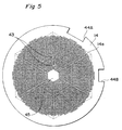
- a mesh plate 14 illustrated in Fig. 5 has still another characterizing feature. This is the fact that a comparatively large closed portion 45 is provided at the center of the mesh plate 14. No minute holes are formed in the closed portion 45.
- the closed portion 45 opposes the opening in the pump bore 22 open at the upper end face of the horn 21A and acts to periodically close the opening as the opening vibrates.
- the valve action (described below) of the mesh plate 14 is reinforced so that more efficient pumping and spraying can be expected.
- the closed portion 45 should be large enough to close the opening in the upper end of the horn 21A.
- the closed portion 45 also is provided in the mesh plate 14 at a position offset from the center thereof so that it will oppose the opening in the upper end of the horn.
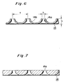
- Fig. 6 illustrates a portion of the cross section of the mesh plate in enlarged form.
- the diameter of the circular minute holes 14a is small at the top surface of the mesh plate 14.
- the holes become successively wider and the diameter successively larger toward the bottom surface of the mesh plate.
- a recess or groove 14b opening toward the top surface is formed on the periphery of each minute hole 14a, namely between the minute holes 14a.
- the mesh plate 14 is installed in the cap 15 in such a manner that the bottom surface of the mesh plate 14 opposes the upper end face of the horn 21A while the top surface opposes the spraying port 51 of the cap 15.
- This mesh plate 14 is characterized in that a comparatively large strength is obtained without making the plate thick.
- the pitch a of the minute holes 14a is 50 ⁇ 150 ⁇ m (a pitch on the order of 100 ⁇ m is suitable)
- the diameter b of the opening of each minute hole 14a in the top surface is on the order of 4.5 ⁇ 1 ⁇ m
- the thickness c of the mesh plate 14 is on the order of 30 ⁇ 100 ⁇ m (a thickness on the order of 50 ⁇ m is suitable).
- Such a mesh plate can be fabricated by combining photoetching and electroforming techniques. Specifically, a number of electrodes are formed on an insulative plate by photoetching so as to correspond to the positions of the centers of the recesses 14b.
- This plate is adopted as a first negative.
- a first metal is deposited on the electrodes by electroforming in such a manner that mutually independent mountains are formed.
- the resulting plate is adopted as a second negative.
- a second metal is further built up uniformly on each mountain of the second negative by electroforming. If the second negative is then peeled off the deposited second metal, a mesh plate comprising the layer of the second metal will be obtained. If it is acceptable for the minute holes to be comparatively large, the mesh plate having the shape shown in Fig. 6 can be fabricated by press work or injection molding.
- Fig. 7 shows another example of the mesh plate, in which the cross section is illustrated in enlarged form.
- Each of the multiplicity of minute holes 14a flares downwardly in such a manner that the diameter of the circular minute holes 14a is small at the top surface of the mesh plate 13 and becomes successively larger toward the bottom surface.
- the material may be metal or a plastic film.
- the minute holes need not be circular.
- the directions in which the surfaces point when the mesh plate has been mounted in the cap is important because the diameters of the minute holes at the top surface and bottom surface differ.
- Fig. 8 illustrates, in enlarged form, the shape of the upper end face of the horn 21A and the relationship among the mesh plate 14, the compression spring 42 and the cap 15.
- the upper end face of the horn 21A is formed so as to be slightly and smoothly curved (spherically) in such a manner that the end face protrudes upwardly to the maximum extent at the center where the pump bore 22 opens.
- the mesh plate 14 is held fast at its periphery by the compression spring 42, as a result of which the mesh plate is caused to flex slightly.
- the difference d between the highest and lowest points of the upper end face of the horn 21A is on the order of 20 ⁇ 50 ⁇ m
- the amount of flexure of the mesh plate 14 is on the order of 5 ⁇ 10 ⁇ m
- the degree of curvature of the upper end face of the horn 21A is greater than the degree of curvature of the mesh plate 14 caused by flexing.
- the vertical (up-and-down) vibration of the horn 12A is accompanied by up-and-down vibration of the mesh plate 14, as mentioned above.
- the minute holes 14a are formed in the mesh plate 14, overall the mesh plate 14 acts as a valve which, by vibrating, opens and closes the opening in the upper end of the pump bore 22.
- liquid pumped up from the pump bore spreads over the upper end face of the horn 21A to form a liquid film when the valve is opened.
- the pumping action is suppressed and the above-mentioned liquid film is atomized through the mesh plate 14.
- Fig. 9 illustrates another embodiment.
- the upper end face of the horn 21A is flat and the mesh plate 14 is curved so as to project downward.
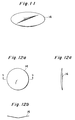
- Fig. 11 is a perspective view of the mesh plate 14.
- Another example of a mesh plate usable in the arrangement shown in Fig. 9 is illustrated in Figs. 12a through 12c.
- the mesh plate 14 is folded slightly and smoothly along a boundary which is a straight line passing through the center of the mesh plate.
- the minute holes are deleted from the illustrations in Fig. 11 and in Figs. 12a through 12c.
- Fig. 10 illustrates yet another embodiment.
- the portion of the upper end face of horn 21A surrounding the opening in the upper end of the pump bore 22 protrudes slightly (the protruding portion is indicated at 21C).
- the diameter of the coil compression spring is set to be the same at all portions.
- the arrangement is such that the compression spring urges the periphery of the mesh plate extending outwardly of the upper end face of the horn.
- the mesh plate is caused to curve into an upwardly directed projection, and hence there is the possibility that the mesh plate will not be able to close off the opening in the upper end of the pump bore.
- the upper end face of the horn is curved so as to project upward, a projection is formed or the mesh plate is curved into a downwardly directly projection.
- a compression spring according to a modification shown in Fig. 13 it is unnecessary to work the upper end face of the horn or the mesh plate.
- the upper end face of the horn is flat and the mesh plate 14 is flat as well.
- the compression spring 42 has a small diameter at its lower portion, with the diameter of the spring growing larger from the bottom to the top. The compression spring 42 urges the mesh plate 14 at the portion thereof on the upper end face of the horn 21A.
- Fig. 14 illustrates another example of the biasing resilient member.
- an annular sponge 46 is used instead of the spring.
- an annular plate 47 simply be placed on the periphery of the mesh plate 14 or that the annular plate be fixed to periphery of the mesh plate 14 by bonding or welding, with the annular plate 47 being urged from above by the compression spring.
- Fig. 16 shows an example in which the width of the annular plate 47 is enlarged so that the inner circumferential portion thereof engages the upper end face of the horn.
- the upper end face of the horn 21A may be flat.
- Fig. 17 illustrates an example in which a spacer 48 instead of the annular plate 47 is interposed between the mesh plate 14 and the upper end face of the horn.
- the spacer 48 is integrally formed to include a small circular portion at its center, an annular portion along its circumference and radiating connecting spokes connecting these two portions.
- the small circular portion at the center should be sized so as to cover the opening of the pump bore 22 in the upper end face of the horn.
- the upper end face of the horn 21A may be flat.
- the annular plate 47 and spacer 48 may both be made of metal or plastic.
- the liquid vessel 16 has a rear wall 65 sloping downward toward the front. Further, both side portions 64A, 64B at the rear of a bottom wall 64 also slope upwardly toward the sides of the vessel. Since the principal mechanical portions of the ultrasonic atomizer are provided in an attitude in which they are inclined downwardly and forwardly, as shown in Fig. 1, the front portion of the bottom wall 64 is inclined downwardly and rearwardly in the state where the liquid vessel 16 is attached. In this way the liquid vessel 16 is formed to have its deepest recess 66, which is delimited by four inclined surfaces 64, 64A, 64B and 65. The lower end portion 21B of the pump shaft 21 is situated directly above the recess 66 in close proximity thereto and in fairly close proximity to the rear wall 65.
- the distance between the lower end face of the pump shaft 21 and the bottom of the recess 66 is on the order of 2 ⁇ 3 mm, and the distance between the rear wall 65 and the part of the peripheral surface of the lower end of the pump shaft 21 that is nearest to the rear wall 65 is on the order of 1 mm.
- the liquid vessel 16 is filled with an appropriate amount of liquid, i.e., to such an extent that the liquid will not overflow.
- the liquid in the liquid vessel 16 decreases as the device is operated to spray the liquid.
- the liquid collects in the deepest recess 66.
- a small amount of the liquid attaches itself to the lower end of the pump shaft 21, as shown at W in Fig. 2, and the liquid is pumped and sprayed to the last drop, owing to the energy of ultrasonic vibration (negative pressure) and the surface tension of the liquid.
- the liquid is inexpensive, as in the case of water or a physiological saline solution, there is no particular inconvenience if some is left. If the liquid is a costly medicine, however, using up all of the liquid in the manner described above is economical since waste is avoided.
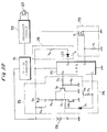
- the electrical circuitry incorporated within the housing 10 of the ultrasonic atomizer comprises a CPU (microprocessor) 70 which controls overall operation, a DC/DC converter 71, an oscillator circuit (and drive circuit) 72, a gate circuit 73, a switch-status detecting circuit 74, a power-supply circuit 75, a display circuit 76 and a battery 79.
- a CPU microprocessor
- the operating voltage of the battery 79 is converted by the DC/DC converter 71 to a voltage suited to the operation of the oscillator circuit 72, and the converted voltage is applied to the oscillator circuit 72, which generates a high-frequency (ultrasonic) signal.
- the oscillating operation of the oscillator circuit 72 is controlled by the CPU 70 via the gate circuit 73.
- the gate circuit 73 comprises a resistor R 1 and a MOS transistor Q 1 .
- the starting and stopping of the oscillating operation of the oscillator circuit 72 is controlled in conformity with the voltage level (H level or L level) which the CPU 70 outputs from an output terminal O 1 .
- the output high-frequency signal is applied to the piezoelectric element 23 through a lead wire 25, whereby the ultrasonic pump 12 operates to perform atomization in the manner set forth above.
- the switch-status detecting circuit 74 detects the on/off state of the switch SW operated by the user and applies the result of detection to the CPU 70.
- the operating switch SW is one type of push-button switch. The switch SW is ON during the time it is being pressed by the user and is turned off when the hand of the user is removed from the operating switch SW.
- the detecting circuit 74 comprises the operating switch SW, a diode D 1 and a pull-up resistor R 2 . When the operating switch SW is turned on, an L-level voltage enters the CPU 70 from its input terminal I 1 . If the switch is off, a high-level voltage enters the CPU 70 from its input terminal I 1 .
- the power-supply circuit 75 controls the supply of operating power from the battery 79 to the CPU 70.
- the power-supply circuit 75 comprises transistors Q2, Q3 and resistors R3, R4, R5, R6 and R7.
- the CPU 70 continues to deliver an H-level ON signal to its output terminal O 2 except in a case where the supply of power is cut off under fixed conditions, as will be understood from a description given later.
- the transistor Q 2 is turned on by this H-level ON signal. Even if the operating switch SW is turned off, the transistor Q 3 is held in the ON state so that the CPU 70 continues to be supplied with operating power.
- the CPU 70 judges that the power supply should be turned off, it inverts the output signal at the output terminal O 2 to the L level. When this is done, the transistor Q2 turns off and the transistor Q3 turns off as long as the switch SW is off. The supply of power to the CPU 70 is halted as a result. Thereafter, power is not supplied to the CPU 70 as long as the user does not turn on the switch SW.
- the display circuit 76 which controls the lighting or flashing of a display device LED, includes a resistor R 8 .
- the CPU 70 causes the L level to appear at an output terminal O 3 thereof in a case where the display device LED is lit. If the display device LED is to be flashed, the CPU outputs a pulse signal of a fixed period (e.g., 5 Hz) at its output terminal O 3 . If the output terminal O 3 is at the H level, the display device LED remains extinguished. It goes without saying that lighting or flashing of the display device LED is performed only in a case where the transistor Q 3 is ON, thereby applying the operating voltage to the CPU 70 and display device LED.
- a fixed period e.g., 5 Hz
- the spraying operation proceeds in continuous fashion even if the operating switch SW is OFF.
- a transition is made to the continuous-operation mode when the operating switch SW is pressed continuously for more than four seconds.
- the transition is made to the continuous-operation mode also in a case where the operating switch SW is pressed continuously for more than four seconds when the automatic intermittent-operation mode (described next) is in effect and in the course of making a transition to the automatic intermittent-operation mode.
- the spraying operation and the halting thereof are repeated at a fixed period even if the operating switch SW is OFF.
- This period of intermittent spraying is decided by learning.
- a transition is made to the automatic intermittent-operation mode by having the user turn on the operating switch repeatedly three times, wherein the switch is turned on for less than four seconds each of the three times.
- the CPU 70 learns the period at which the operating switch is turned on and off (namely the ON time and the OFF time) and decides the period of intermittency (the ON/OFF repetition period) in the automatic intermittent-operation mode.
- the automatic intermittent-operation mode is particularly effective in a case where the ultrasonic atomizer is applied to an inhaler.
- an inhaler atomized medicine is drawn in to the throat only when the user inhales.
- the medicinal inhalant used is expensive.
- the learning process the period (time) at which the user turns the operating switch on and off is measured, whereby learning is performed. Even if the switch SW is not turned on and off after learning, the spraying operation and termination thereof are repeated automatically at a repetition period that conforms to the user's breathing. This is particularly useful for the elderly and children, who cannot perform the on/off operation skillfully.
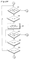
- the operation of the CPU 70 is started in response to the operating switch SW being turned on by the user.
- the CPU 70 outputs an H-level signal at its output terminal O 2 , thereby turning on the transistor Q 2 (step 111).
- the operating voltage is applied to the CPU 70 irrespective of the on/off operation of the switch SW, as described above.
- step 112 If the operating switch SW is turned on continuously for more than four seconds (YES at step 112), a transition is made to the continuous-operation mode and a display to this effect is presented (step 113).
- the display device LED starts to flash and continues flashing until the switch is turned off, thereby indicating the fact that a transition has been made to the continuous-operation mode, as shown in Fig. 26a.
- the display device LED remains lit until elapse of four seconds from the moment the operating switch SW is turned on as well as during operation in the continuous-operation mode. The spraying operation is performed continuously from the moment the operating switch SW is turned on.
- the spraying operation in the continuous-operation mode continues as long as the operating switch SW is not turned off subsequently (NO at step 114) and the operating switch SW is not turned on again (NO at step 115).
- the CPU 70 sends the output at its output terminal O 2 to the L level to cut off the supply of electric power (step 118).
- a learning counter N is cleared (step 120).
- the results of the first learning operation namely the results of measuring the preceding ON and OFF times of the switch, are accepted, one ON/OFF period is calculated and the learning counter N is incremented (step 122).
- the ON and OFF times of the switch SW are measured constantly by a timer or counter.
- the average ON/OFF period is calculated (step 127) since the value in the learning counter N is already 2 (YES at step 126). That is, since the results of the second learning operation have already been stored, the average value of the ON time and the average value of the OFF time are calculated and these average values are decided on as the ON time and OFF time in the automatic intermittent-operation mode.
- the automatic intermittent-operation mode in which the spraying operation is performed intermittently at the period of the previously decided ON time and OFF time as long as the switch SW is OFF. Further, as shown in Fig. 26b, the display device LED flashes from the moment the operating switch SW is turned off the third time until the elapse of four seconds from the moment at which the operating switch SW was turned on the third time. This presents a display indicating that a transition is being made to the automatic intermittent-operation mode (step 128).
- the display device LED is lit during the times that the operating switch SW is ON in the first through third operations thereof and when the spraying operation is being performed in the automatic intermittent-operation mode. Further, it goes without saying that the spraying operation also is carried out during the times that the operating switch SW is ON in the first through third operations thereof.
- step 118 When the operating switch SW is subsequently turned on again for less than four seconds (YES at step 129, NO at step 130 and YES at step 131), the power supply is turned off (step 118).
- a learning operation is performed two times.
- an arrangement may be adopted in which the ON time and OFF time of the operating switch SW are measured over a large number of times and the ON/OFF period in the automatic intermittent-operation mode is decided based upon the results.
- a manual mode may be provided in which the user is capable of turning the operating switch on and off at all times to control the intermittency of spraying in accordance with this ON/OFF operation.
- a transition is made to the automatic intermittent-operation mode only after the third ON operation of the operating switch is rendered intermittent for more than four seconds.
- a special switch for designating the automatic intermittent-operation mode can be provided. In this case also it goes without saying that learning can be performed one time or a plurality of times.
- Ultrasonic inhalers are utilized in the medical-instrument industry.
Landscapes
- Health & Medical Sciences (AREA)
- Engineering & Computer Science (AREA)
- Bioinformatics & Cheminformatics (AREA)
- Pulmonology (AREA)
- Anesthesiology (AREA)
- Biomedical Technology (AREA)
- Heart & Thoracic Surgery (AREA)
- Hematology (AREA)
- Life Sciences & Earth Sciences (AREA)
- Animal Behavior & Ethology (AREA)
- General Health & Medical Sciences (AREA)
- Public Health (AREA)
- Veterinary Medicine (AREA)
- Special Spraying Apparatus (AREA)
- Closures For Containers (AREA)
- Structures Of Non-Positive Displacement Pumps (AREA)
Abstract
Claims (22)
- Atomiseur à ultrasons comprenant une pompe à ultrasons (12) ayant un arbre de pompe (21) formé de sorte à avoir un alésage de pompe (22) le traversant de manière axiale et ayant les extrémités supérieure et inférieure ouvertes et un vibrateur à ultrasons (23) monté sur l'arbre de pompe à proximité de son point central par rapport à la direction axiale, un récipient à liquide (16) prévu à un emplacement où il est pénétré par l'extrémité inférieure dudit arbre de pompe et une plaque maillée (14) placée sur une face terminale supérieure dudit arbre de pompe et formée de sorte à avoir une multiplicité de trous minuscules (14a),
caractérisé en ce qu'il comprend également un élément élastique de retour (42) agissant sur la surface supérieure de ladite plaque maillée (14), à l'opposé de celle faisant face audit arbre de pompe (21) et appuyant sur ladite plaque maillée depuis le haut, vers ladite face terminale supérieure dudit arbre de pompe. - Atomiseur à ultrasons conforme à la revendication 1, caractérisé en ce qu'il comprend également :un boítier (10), auquel ledit récipient à liquide est fixé d'une manière amovible, pour supporter ladite pompe à ultrasons ; etun bouchon (15) fixé à une partie dudit boítier d'une manière amovible de sorte à couvrir l'extrémité supérieure dudit arbre de pompe ;un côté supérieur dudit bouchon étant prévu avec un orifice de pulvérisation (51), une partie à gradins (57) étant formée pour supporter ladite plaque maillée à sa périphérie, en dessous dudit orifice de pulvérisation et ledit élément élastique de retour étant placé entre une partie du côté supérieur dudit bouchon et ladite plaque maillée.
- Atomiseur à ultrasons conforme à la revendication 1 ou 2, caractérisé en ce que ladite plaque maillée est repoussée par ledit élément élastique de retour de sorte à entrer en contact avec la face terminale supérieure dudit arbre de pompe au moins dans une zone de ladite face terminale supérieure qui inclut l'ouverture dans l'extrémité supérieure de l'alésage de pompe.
- Atomiseur à ultrasons conforme à l'une des revendications 1 à 3, caractérisé en ce que la face terminale supérieure dudit arbre de pompe présente une forme telle que la face terminale supérieure est légèrement et doucement courbée afin d'atteindre la hauteur maximale à l'emplacement de l'ouverture dans l'extrémité supérieure de l'alésage de pompe et de diminuer en hauteur à l'approche de la périphérie.
- Atomiseur à ultrasons conforme à la revendication 4, caractérisé en ce que ladite plaque maillée est courbée légèrement en étant repoussée par ledit élément élastique de retour au bord périphérique s' étendant vers l'extérieur depuis la face terminale supérieure dudit arbre de pompe et en ce que la courbure de ladite face terminale supérieure dudit arbre de pompe, la force élastique dudit élément élastique de retour et la force de ladite plaque maillée sont décidées de telle sorte que le degré de courbure de ladite plaque maillée est inférieur au degré de courbure de la face terminale supérieure dudit arbre de pompe.
- Atomiseur à ultrasons conforme à l'une des revendications 1 à 3, caractérisé en ce que ladite face terminale supérieure dudit arbre de pompe est formée de sorte à avoir une protubérance (21C) qui se projette dans une zone comprenant l'ouverture dans l'extrémité supérieure dudit alésage de pompe.
- Atomiseur à ultrasons conforme à l'une des revendications 1 à 3, caractérisé en ce que ladite plaque maillée est formée de telle sorte que sa partie centrale est pliée ou courbée légèrement afin de pointer vers la bas.
- Atomiseur à ultrasons conforme à l'une des revendications 1 à 7, caractérisé en ce que ledit élément élastique de retour est un ressort hélicoïdal comprimé.
- Atomiseur à ultrasons conforme à l'une des revendications 1 à 7, caractérisé en ce que ledit élément élastique de retour est un ressort hélicoïdal comprimé ayant un diamètre d'hélice qui diminue progressivement en approchant de ladite plaque maillée, de telle sorte que ladite plaque maillée est inclinée à un emplacement situé sur la face terminale supérieure dudit arbre de pompe.
- Atomiseur à ultrasons conforme à l'une des revendications 1 à 9, caractérisé en ce que les trous minuscules de ladite plaque maillée sont formés de sorte à s'évaser vers l'extérieur dans une direction s'étendant entre le côté supérieur et le côté inférieur de ladite plaque maillée.
- Atomiseur à ultrasons conforme à l'une des revendications 1 à 9, caractérisé en ce que ladite plaque maillée (14) est formée de telle sorte que les trous minuscules (14a) s'évasent vers l'extérieur dans une direction s'étendant entre le côté supérieur et le côté inférieur de ladite plaque maillée et en ce qu'une rainure ou retrait (14b) est formé dans le côté supérieur entre des trous minuscules mutuellement adjacents.
- Atomiseur à ultrasons conforme à l'une des revendications 1 à 11, caractérisé en ce que des découpes (44A, 44B) de différente taille sont formées dans la périphérie de ladite plaque maillée au moins à deux emplacements autres que les emplacements à symétrie ponctuelle avec le centre de ladite plaque maillée.
- Atomiseur à ultrasons conforme à l'une des revendications 1 à 12, caractérisé en ce que lesdits trous minuscules sont formés à des intervalles égaux le long des côtés d'une multiplicité d'hexagones réguliers dont les diagonales varient à des distances fixes.
- Atomiseur à ultrasons conforme à l'une des revendications 1 à 13, caractérisé en ce qu'une petite zone (43) sans trou minuscule est présente dans ladite plaque maillée dans une zone entourée par lesdits trous minuscules.
- Atomiseur à ultrasons conforme à l'une des revendications 1 à 14, caractérisé en ce qu'une zone (45) sans trou minuscule est présente dans ladite plaque maillée, à un emplacement opposé à l'ouverture dans l'extrémité supérieure de l'alésage de pompe dudit arbre de pompe, sur une région plus large que ladite ouverture.
- Atomiseur à ultrasons conforme à l'une des revendications 1 à 15, caractérisé en ce que la partie périphérique de ladite plaque maillée dispose d'une plaque annulaire (47) afin que la force d'inclinaison produite par ledit élément élastique de retour soit appliquée à ladite plaque maillée de manière uniforme.
- Atomiseur à ultrasons conforme à l'une des revendications 1 à 15, caractérisé en ce qu'un intercalaire (48) est placé entre ladite plaque maillée et la face terminale supérieure dudit arbre de pompe.
- Atomiseur à ultrasons conforme à la revendication 1, caractérisé en ce qu'il comprend également un manchon (31) permettant d'encercler et de supporter, de manière imperméable, une partie dudit arbre de pompe de ladite pompe à ultrasons excluant les parties terminales supérieure et inférieure dudit arbre de pompe ;une lèvre de joint annulaire (34A, 34B), en contact étroit et imperméable avec une partie de l'arbre de pompe situé plus haut que ledit vibrateur à ultrasons, étant formée intégralement à, au moins, deux emplacements, l'un au-dessus de l'autre, sur une partie supérieure dudit manchon, et un espace (35) étant prévu entre ladite partie de l'arbre de pompe et ledit manchon entre les lèvres de joint annulaires, au moins, aux deux emplacements situés l'un au-dessus de l'autre.
- Atomiseur à ultrasons conforme à la revendication 1, caractérisé an ce qu'il comprend également :un manchon (31) permettant d'encercler et de supporter, de manière imperméable, une partie dudit arbre de pompe de ladite pompe à ultrasons excluant les parties terminales supérieure et inférieure dudit arbre de pompe ;un boítier (10) dans lequel ledit manchon est fixé de manière imperméable ;un bouchon (15) fixé de manière amovible à une paroi saillante annulaire (59), qui est formée sur ledit boítier vers la partie terminale supérieure dudit arbre de pompe, de sorte à couvrir la partie terminale supérieure dudit arbre de pompe ; etun réservoir (56) formé avec un côté supérieur dudit manchon servant de surface inférieure et au moins l'un dudit bouchon et de ladite paroi saillante annulaire servant de paroi périphérique.
- Atomiseur à ultrasons conforme à la revendication 1, caractérisé en ce qu'une extrémité inférieure dudit arbre de pompe est placée à proximité d'une surface inférieure ou d'une surface latérale dudit récipient à liquide de telle sorte que le liquide résiduel restant à l'intérieur dudit récipient à liquide est pompé en étant attachée à l'extrémité inférieure de l'arbre de pompe par la tension de surface.
- Atomiseur à ultrasons conforme à l'une des revendications 1 à 20, caractérisé en ce que ledit récipient à liquide est formé de sorte à avoir un retrait (66) permettant de collecter le liquide résiduel restant à l'intérieur dudit récipient à liquide et en ce que l'extrémité inférieure dudit arbre de pompe est placée de sorte à faire face audit retrait.
- Atomiseur à ultrasons conforme à la revendication 1, caractérisé en ce qu'il comprend également :un circuit d'entraínement (72) permettant d'entraíner le vibrateur à ultrasons de ladite pompe à ultrasons ;un interrupteur de service (SW) ;un premier moyen de commande (70, 73) répondant à la mise en marche/à l'arrêt dudit interrupteur de service permettant de contrôler l'entraínement dudit vibrateur à ultrasons par ledit circuit d'entraínement ; etun deuxième moyen de commande (70, 74) qui, en réponse à la mise en marche/à l'arrêt, une fois ou plusieurs fois, dudit interrupteur de service, décide du temps MARCHE et du temps ARRET en fonctionnement intermittent automatique sur la base du temps MARCHE et du temps ARRET dudit interrupteur de service et contrôle ledit circuit d'entraínement de telle sorte que ledit vibrateur à ultrasons est entraíné à une période du temps MARCHE et du temps ARRET décidée.
Priority Applications (1)
| Application Number | Priority Date | Filing Date | Title |
|---|---|---|---|
| EP99105093A EP0933138B1 (fr) | 1992-04-09 | 1993-04-09 | Atomiseur à ultrasons |
Applications Claiming Priority (13)
| Application Number | Priority Date | Filing Date | Title |
|---|---|---|---|
| JP8846392 | 1992-04-09 | ||
| JP88463/92 | 1992-04-09 | ||
| JP8846392 | 1992-04-09 | ||
| JP9085292 | 1992-04-10 | ||
| JP8921492 | 1992-04-10 | ||
| JP90852/92 | 1992-04-10 | ||
| JP9085292 | 1992-04-10 | ||
| JP92649/92 | 1992-04-13 | ||
| JP9264992 | 1992-04-13 | ||
| JP94043/92 | 1992-04-14 | ||
| JP9404392 | 1992-04-14 | ||
| JP9404392 | 1992-04-14 | ||
| PCT/JP1993/000454 WO1993020949A1 (fr) | 1992-04-09 | 1993-04-09 | Atomiseur a ultrasons, inhalateur a ultrasons et procede de commande de ceux-ci |
Related Child Applications (1)
| Application Number | Title | Priority Date | Filing Date |
|---|---|---|---|
| EP99105093A Division EP0933138B1 (fr) | 1992-04-09 | 1993-04-09 | Atomiseur à ultrasons |
Publications (3)
| Publication Number | Publication Date |
|---|---|
| EP0635312A1 EP0635312A1 (fr) | 1995-01-25 |
| EP0635312A4 EP0635312A4 (fr) | 1996-01-10 |
| EP0635312B1 true EP0635312B1 (fr) | 2000-07-26 |
Family
ID=27525348
Family Applications (1)
| Application Number | Title | Priority Date | Filing Date |
|---|---|---|---|
| EP93908070A Expired - Lifetime EP0635312B1 (fr) | 1992-04-09 | 1993-04-09 | Atomiseur a ultrasons |
Country Status (6)
| Country | Link |
|---|---|
| US (2) | US6651650B1 (fr) |
| EP (1) | EP0635312B1 (fr) |
| JP (1) | JP2546439B2 (fr) |
| DE (2) | DE69329110T2 (fr) |
| ES (1) | ES2149204T3 (fr) |
| WO (1) | WO1993020949A1 (fr) |
Families Citing this family (118)
| Publication number | Priority date | Publication date | Assignee | Title |
|---|---|---|---|---|
| US6540154B1 (en) | 1991-04-24 | 2003-04-01 | Aerogen, Inc. | Systems and methods for controlling fluid feed to an aerosol generator |
| US7628339B2 (en) | 1991-04-24 | 2009-12-08 | Novartis Pharma Ag | Systems and methods for controlling fluid feed to an aerosol generator |
| EP0635312B1 (fr) * | 1992-04-09 | 2000-07-26 | Omron Corporation | Atomiseur a ultrasons |
| JP2833436B2 (ja) | 1993-09-14 | 1998-12-09 | オムロン株式会社 | 超音波式吸入器 |
| US6085740A (en) | 1996-02-21 | 2000-07-11 | Aerogen, Inc. | Liquid dispensing apparatus and methods |
| US6782886B2 (en) * | 1995-04-05 | 2004-08-31 | Aerogen, Inc. | Metering pumps for an aerosolizer |
| US5758637A (en) | 1995-08-31 | 1998-06-02 | Aerogen, Inc. | Liquid dispensing apparatus and methods |
| US6205999B1 (en) * | 1995-04-05 | 2001-03-27 | Aerogen, Inc. | Methods and apparatus for storing chemical compounds in a portable inhaler |
| US6273342B1 (en) | 1997-10-06 | 2001-08-14 | Omron Corporation | Atomizer |
| US6235177B1 (en) | 1999-09-09 | 2001-05-22 | Aerogen, Inc. | Method for the construction of an aperture plate for dispensing liquid droplets |
| US6962151B1 (en) * | 1999-11-05 | 2005-11-08 | Pari GmbH Spezialisten für effektive Inhalation | Inhalation nebulizer |
| BE1013168A3 (fr) * | 1999-12-03 | 2001-10-02 | Univ Catholique De Louvain Hal | Pulverisateur comprenant une extremite active de forme specifique et extremite active de pulverisateur utltrasonique. |
| US6948491B2 (en) | 2001-03-20 | 2005-09-27 | Aerogen, Inc. | Convertible fluid feed system with comformable reservoir and methods |
| US8336545B2 (en) | 2000-05-05 | 2012-12-25 | Novartis Pharma Ag | Methods and systems for operating an aerosol generator |
| MXPA02010884A (es) | 2000-05-05 | 2003-03-27 | Aerogen Ireland Ltd | Aparato y metodo para el suministro de medicamentos al sistema respiratorio. |
| US7600511B2 (en) | 2001-11-01 | 2009-10-13 | Novartis Pharma Ag | Apparatus and methods for delivery of medicament to a respiratory system |
| US7100600B2 (en) | 2001-03-20 | 2006-09-05 | Aerogen, Inc. | Fluid filled ampoules and methods for their use in aerosolizers |
| US7971588B2 (en) | 2000-05-05 | 2011-07-05 | Novartis Ag | Methods and systems for operating an aerosol generator |
| JP3821095B2 (ja) | 2000-10-05 | 2006-09-13 | オムロンヘルスケア株式会社 | 液体噴霧装置 |
| DE60140904D1 (de) * | 2000-11-16 | 2010-02-04 | Zakrytoe Aktsionernoe Obschest | Vorrichtung zur aromatisierung eines gasmediums |
| WO2002074372A2 (fr) * | 2001-03-15 | 2002-09-26 | The Government Of The United States Of America As Represented By The Secretary Of The Department Of Health And Human Services | Systemes et procedes de diffusion d'agents par aerosol |
| US6732944B2 (en) | 2001-05-02 | 2004-05-11 | Aerogen, Inc. | Base isolated nebulizing device and methods |
| EP1436028A4 (fr) * | 2001-09-12 | 2007-04-04 | Ivax U K Ltd | Nebuliseur ultrasonore facilitant la respiration et ampoule de dose unitaire associee |
| US7677467B2 (en) | 2002-01-07 | 2010-03-16 | Novartis Pharma Ag | Methods and devices for aerosolizing medicament |
| MXPA04006629A (es) | 2002-01-07 | 2004-11-10 | Aerogen Inc | Aparatos y metodos para nebulizar fluidos para inhalacion. |
| ES2603067T3 (es) | 2002-01-15 | 2017-02-23 | Novartis Ag | Métodos y sistemas para hacer funcionar un generador de aerosol |
| AU2003256253A1 (en) | 2002-05-20 | 2003-12-02 | Aerogen, Inc. | Aerosol for medical treatment and methods |
| US6843430B2 (en) * | 2002-05-24 | 2005-01-18 | S. C. Johnson & Son, Inc. | Low leakage liquid atomization device |
| US8012136B2 (en) | 2003-05-20 | 2011-09-06 | Optimyst Systems, Inc. | Ophthalmic fluid delivery device and method of operation |
| EP1624938B1 (fr) * | 2003-05-20 | 2011-03-16 | James F. Collins | Systeme de distribution de medicaments ophtalmiques |
| US8616195B2 (en) | 2003-07-18 | 2013-12-31 | Novartis Ag | Nebuliser for the production of aerosolized medication |
| US20070235555A1 (en) * | 2006-04-11 | 2007-10-11 | Helf Thomas A | Electronic aerosol device |
| US7517568B2 (en) * | 2004-03-23 | 2009-04-14 | The Clorox Company | Packaging for dilute hypochlorite |
| WO2006006963A2 (fr) * | 2004-04-02 | 2006-01-19 | The Government Of The United States Of America As Represented By The Secretary Of The Department Of Health And Human Services, Centers For Disease Control And Prevention | Systemes et procedes de distribution par aerosols |
| US7290541B2 (en) | 2004-04-20 | 2007-11-06 | Aerogen, Inc. | Aerosol delivery apparatus and method for pressure-assisted breathing systems |
| US7267121B2 (en) | 2004-04-20 | 2007-09-11 | Aerogen, Inc. | Aerosol delivery apparatus and method for pressure-assisted breathing systems |
| US7946291B2 (en) | 2004-04-20 | 2011-05-24 | Novartis Ag | Ventilation systems and methods employing aerosol generators |
| EP1604701B1 (fr) * | 2004-06-09 | 2010-12-15 | Microflow Engineering SA | Dispositif de pulverisation de liquide amélioré modulair |
| DE102005022339B3 (de) * | 2005-05-13 | 2006-10-12 | Pari GmbH Spezialisten für effektive Inhalation | Inhalationstherapievorrichtung mit Verneblerdüse und Kompressor |
| AU2006251850B2 (en) * | 2005-05-23 | 2010-02-18 | Biosonic Australia Pty. Ltd. | Apparatus for atomisation and liquid filtration |
| ES2514470T3 (es) | 2005-05-25 | 2014-10-28 | Aerogen, Inc. | Sistemas y métodos de vibración |
| JPWO2006129807A1 (ja) * | 2005-06-03 | 2009-01-08 | 超音波醸造所有限会社 | 溶液の反応装置と反応方法 |
| US9101949B2 (en) | 2005-08-04 | 2015-08-11 | Eilaz Babaev | Ultrasonic atomization and/or seperation system |
| US20070031611A1 (en) * | 2005-08-04 | 2007-02-08 | Babaev Eilaz P | Ultrasound medical stent coating method and device |
| US7896539B2 (en) | 2005-08-16 | 2011-03-01 | Bacoustics, Llc | Ultrasound apparatus and methods for mixing liquids and coating stents |
| TWM297751U (en) * | 2006-03-21 | 2006-09-21 | Taidoc Technology Corp | Liquid nebulizer |
| JP2008023026A (ja) * | 2006-07-20 | 2008-02-07 | Alfresa Pharma Corp | 噴霧機及び噴霧機の洗浄方法 |
| FR2908329B1 (fr) * | 2006-11-14 | 2011-01-07 | Telemaq | Dispositif et methode de distribution de fluide par ultrasons |
| WO2008097645A1 (fr) * | 2007-02-08 | 2008-08-14 | Aerovectrx Corporation | Systèmes et procédés de distribution d'aérosol |
| USD597206S1 (en) | 2007-02-16 | 2009-07-28 | Optimyst Systems, Inc. | Ophthalmic misting device |
| US7789278B2 (en) * | 2007-04-12 | 2010-09-07 | The Clorox Company | Dual chamber aerosol container |
| RU2349392C2 (ru) * | 2007-04-20 | 2009-03-20 | Общество с ограниченной ответственностью "Производственно-техническое и технологическое предприятие "Титан-А" (ООО "ПТ и ТП "Титан-А") | Ультразвуковой распылитель жидких препаратов различной вязкости |
| CN101743030B (zh) * | 2007-06-29 | 2013-08-07 | 默梅德凯尔股份有限公司 | 一种用于气道管理系统的气体混合装置 |
| US7901388B2 (en) | 2007-07-13 | 2011-03-08 | Bacoustics, Llc | Method of treating wounds by creating a therapeutic solution with ultrasonic waves |
| US7780095B2 (en) | 2007-07-13 | 2010-08-24 | Bacoustics, Llc | Ultrasound pumping apparatus |
| US7753285B2 (en) | 2007-07-13 | 2010-07-13 | Bacoustics, Llc | Echoing ultrasound atomization and/or mixing system |
| US7896854B2 (en) * | 2007-07-13 | 2011-03-01 | Bacoustics, Llc | Method of treating wounds by creating a therapeutic solution with ultrasonic waves |
| US8689728B2 (en) * | 2007-10-05 | 2014-04-08 | Menendez Adolfo | Apparatus for holding a medical device during coating |
| US20090093870A1 (en) * | 2007-10-05 | 2009-04-09 | Bacoustics, Llc | Method for Holding a Medical Device During Coating |
| EP2050479A3 (fr) * | 2007-10-16 | 2013-06-19 | General Electric Company | Appareil, système et procédé d'administration d'un agent anesthétique pour la respiration d'un patient |
| US20090212133A1 (en) * | 2008-01-25 | 2009-08-27 | Collins Jr James F | Ophthalmic fluid delivery device and method of operation |
| US8016208B2 (en) | 2008-02-08 | 2011-09-13 | Bacoustics, Llc | Echoing ultrasound atomization and mixing system |
| US7950594B2 (en) * | 2008-02-11 | 2011-05-31 | Bacoustics, Llc | Mechanical and ultrasound atomization and mixing system |
| US7830070B2 (en) * | 2008-02-12 | 2010-11-09 | Bacoustics, Llc | Ultrasound atomization system |
| US20090242660A1 (en) * | 2008-03-25 | 2009-10-01 | Quatek Co., Ltd. | Medical liquid droplet apparatus |
| EP2119465A1 (fr) | 2008-05-16 | 2009-11-18 | Markos Mefar S.P.A. | Nébuliseur doté d'un capteur de détection de la phase respiratoire pour l'administration de médicaments nébulisés à un utilisateur |
| US20090192443A1 (en) * | 2008-10-06 | 2009-07-30 | Collins Jr James F | Ophthalmic fluid delivery device and method of operation |
| DE102009001037B4 (de) * | 2009-02-20 | 2013-02-21 | Pari Pharma Gmbh | Inhalationstherapievorrichtung |
| GB2472416B (en) * | 2009-08-05 | 2012-12-19 | Quatek Co Ltd | Medical liquid droplet apparatus |
| CN102596296B (zh) * | 2009-11-11 | 2015-07-22 | 皇家飞利浦电子股份有限公司 | 药物输送设备和方法 |
| EP2523710B1 (fr) | 2010-01-11 | 2015-10-14 | Koninklijke Philips N.V. | Couplage magnétique pour appareil produisant un aérosol |
| CN102711880B (zh) | 2010-01-11 | 2015-11-25 | 皇家飞利浦电子股份有限公司 | 用于气雾剂产生器械的磁力联接 |
| US20110232312A1 (en) * | 2010-03-24 | 2011-09-29 | Whirlpool Corporation | Flexible wick as water delivery system |
| US20110232321A1 (en) * | 2010-03-24 | 2011-09-29 | Whirlpool Corporation | Atomization of food preservation solution |
| US10154923B2 (en) | 2010-07-15 | 2018-12-18 | Eyenovia, Inc. | Drop generating device |
| CA2805635A1 (fr) | 2010-07-15 | 2012-01-19 | Corinthian Ophthalmic, Inc. | Procede et systeme de realisation d'un traitement et d'une surveillance a distance |
| CA2805426C (fr) | 2010-07-15 | 2020-03-24 | Corinthian Ophthalmic, Inc. | Dispositif de generation de gouttelettes |
| KR20130051476A (ko) | 2010-07-15 | 2013-05-20 | 코린시언 아프샐믹 인코포레이티드 | 안과용 약물 전달 |
| EP3508083B1 (fr) | 2010-08-24 | 2021-07-14 | JT International S.A. | Dispositif d'inhalation comprenant des commandes d'usage de substance |
| TWM425720U (en) * | 2011-11-08 | 2012-04-01 | Microbase Technology Corp | Atomization structure |
| JP2013118952A (ja) * | 2011-12-07 | 2013-06-17 | Dainippon Printing Co Ltd | 噴霧デバイス用の液体カートリッジ、液体カートリッジパッケージ、噴霧デバイス及び噴霧デバイス用のメッシュ付容器 |
| US20130172830A1 (en) | 2011-12-12 | 2013-07-04 | Corinthian Ophthalmic, Inc. | Ejector mechanism, ejector device, and methods of use |
| US9603906B2 (en) | 2012-02-01 | 2017-03-28 | Protalix Ltd. | Inhalable liquid formulations of DNase I |
| EP3421042B1 (fr) | 2012-03-07 | 2024-04-17 | Beyond Air Ltd | Inhalation d'oxyde nitrique pour traiter des maladies des voies respiratoires |
| EP2849692A1 (fr) * | 2012-05-14 | 2015-03-25 | Eyenovia, Inc. | Dispositif générateur de gouttelettes en flux laminaire et procédés d'utilisation |
| JP2014004208A (ja) * | 2012-06-26 | 2014-01-16 | Omron Healthcare Co Ltd | 液体噴霧装置 |
| US10112203B2 (en) | 2013-04-17 | 2018-10-30 | S.C. Johnson & Son, Inc. | Portable volatile material dispenser and method of simulating a flame in same |
| WO2015022436A1 (fr) * | 2013-08-16 | 2015-02-19 | Vectura Gmbh | Système de dosage pour un dispositif d'inhalation |
| CN105764616A (zh) | 2013-09-09 | 2016-07-13 | 奥姆纽斯特有限责任公司 | 喷雾装置 |
| US20160256589A1 (en) * | 2013-10-01 | 2016-09-08 | Tsafrir Sasson | System and method for dispensing liquids |
| EP2883564A1 (fr) | 2013-12-16 | 2015-06-17 | PARI Pharma GmbH | Dispositif d'administration d'aérosol et procédé de fonctionnement dudit dispositif |
| EP3240896A1 (fr) | 2015-01-04 | 2017-11-08 | Protalix Ltd. | Dnase modifiée et ses utilisations |
| JP6480598B2 (ja) | 2015-04-02 | 2019-03-13 | ヒル−ロム サービシーズ プライヴェート リミテッド | 呼吸装置用マニホールド |
| RU2721489C2 (ru) | 2015-10-30 | 2020-05-19 | Джонсон энд Джонсон Консьюмер Инк. | Асептический аэрозольный туманообразователь |
| MA54688A (fr) | 2015-10-30 | 2021-11-17 | Johnson & Johnson Consumer Inc | Nébuliseur d'aérosol aseptique |
| WO2017075318A1 (fr) | 2015-10-30 | 2017-05-04 | Johnson & Johnson Consumer Inc. | Nébuliseur d'aérosol aseptique |
| IL258643B2 (en) | 2015-10-30 | 2023-03-01 | Johnson & Johnson Consumer Inc | Dosing unit for an uncontaminated spray misting device |
| JP6137654B2 (ja) * | 2016-04-07 | 2017-05-31 | 大日本印刷株式会社 | 噴霧デバイス用の液体カートリッジ、液体カートリッジパッケージ、噴霧デバイス及び噴霧デバイス用のメッシュ付容器 |
| KR102122887B1 (ko) | 2016-05-03 | 2020-06-16 | 뉴마 레스퍼러토리 인코포레이티드 | 유체들의 폐기관계로의 전달을 위한 액적 전달 디바이스 및 사용 방법 |
| US20170348495A1 (en) * | 2016-06-06 | 2017-12-07 | Nicholas A. Havercroft | Modified nebulizer, method and system for delivering pharmaceutical products to an individual |
| US20180071274A1 (en) * | 2016-06-06 | 2018-03-15 | Nicholas A. Havercroft | Medical product for reducing and/or eliminating symptoms of nicotine withdrawal |
| EP3375473A1 (fr) * | 2017-03-17 | 2018-09-19 | PARI Pharma GmbH | Dispositif de commande pour système nébuliseur d'aérosol |
| US11938056B2 (en) | 2017-06-10 | 2024-03-26 | Eyenovia, Inc. | Methods and devices for handling a fluid and delivering the fluid to the eye |
| CN111163821B (zh) | 2017-08-02 | 2023-02-17 | 泰利福医疗公司 | 用于快速药物传送的医用雾化器 |
| CN118203735A (zh) | 2017-10-04 | 2024-06-18 | 精呼吸股份有限公司 | 电子呼吸致动式直线型液滴输送装置及其使用方法 |
| CA3082192A1 (fr) | 2017-11-08 | 2019-05-16 | Pneuma Respiratory, Inc. | Dispositif electronique d'administration de gouttelettes, en ligne, actionne par la respiration, dote d'une ampoule de faible volume, et methodes d'utilisation |
| US10933205B2 (en) | 2017-11-30 | 2021-03-02 | Aura Medical LLC | Portable heated mist inhaler |
| CN108392706A (zh) * | 2017-12-29 | 2018-08-14 | 合肥美菱净化设备有限公司 | 一种低频超声医用雾化器装置 |
| EP3603617A1 (fr) * | 2018-07-30 | 2020-02-05 | Sterna Biologicals GmbH & Co. KG | Dispositif générateur d'aérosol destiné à l'administration par inhalation d'une composition contenant une molécule antisens |
| EP3666315A1 (fr) | 2018-12-14 | 2020-06-17 | PARI Pharma GmbH | Dispositif d'administration d'aérosol et procédé de fonctionnement du dispositif d'administration d'aérosol |
| EP3666316A1 (fr) | 2018-12-14 | 2020-06-17 | PARI Pharma GmbH | Dispositif d'administration d'aérosol et procédé pour faire fonctionner un dispositif d'administration d'aérosol |
| US11510809B2 (en) | 2019-05-14 | 2022-11-29 | Twenty Twenty Therapeutics Llc | Non-gravitational fluid delivery device for ophthalmic applications |
| CA3164288A1 (fr) | 2019-12-11 | 2021-06-17 | Eyenovia, Inc. | Systemes et dispositifs d'administration de fluides a l'oeil et procedes d'utilisation |
| DE102020204134A1 (de) | 2020-03-30 | 2021-09-30 | Robert Bosch Gesellschaft mit beschränkter Haftung | Medienausgabevorrichtung, Medienauftragungssystem, Verfahren zu einer gezielten Ausgabe eines Mediums mittels einer Medienausgabevorrichtung und Verwendung einer Medienausgabevorrichtung zu einem Auftragen einer Farbe |
| WO2022271848A1 (fr) | 2021-06-22 | 2022-12-29 | Pneuma Respiratory, Inc. | Dispositif de distribution de gouttelettes avec éjection par poussée |
| WO2023091637A1 (fr) * | 2021-11-18 | 2023-05-25 | Pneuma Respiratory, Inc. | Dispositif de distribution de gouttelettes pour le traitement d'affections oculaires |
| US20260033533A1 (en) | 2022-07-18 | 2026-02-05 | Pneuma Respiratory, Inc. | Small step size and high resolution aerosol generation system and method |
| US20250115121A1 (en) * | 2023-10-09 | 2025-04-10 | Roger Hayes | Pump system for liquid transport tank |
Family Cites Families (60)
| Publication number | Priority date | Publication date | Assignee | Title |
|---|---|---|---|---|
| US427651A (en) * | 1890-05-13 | wriaht | ||
| US1246682A (en) * | 1915-06-14 | 1917-11-13 | Alfred H Thompson | Adjustable non-flash gas-burner. |
| US1215229A (en) * | 1916-09-23 | 1917-02-06 | Samuel Tully Willson | Fluid-fuel burner. |
| US1482529A (en) * | 1922-05-31 | 1924-02-05 | Hartman Spreng Company | Gas burner |
| US1463263A (en) * | 1922-09-23 | 1923-07-31 | John H Grayson | Burner tip |
| US1721381A (en) * | 1928-02-02 | 1929-07-16 | Gen Electric | Gas burner |
| CH244781A (de) * | 1945-02-27 | 1946-09-30 | Junghans Heinrich | Inhalationsapparat. |
| US2559559A (en) * | 1947-01-02 | 1951-07-03 | Isenberg Stanley | Spray head |
| US2744194A (en) * | 1951-06-21 | 1956-05-01 | Auerbach Martin | Alert device for attaching to radio receiving sets |
| US2855244A (en) * | 1955-06-03 | 1958-10-07 | Bendix Aviat Corp | Sonic liquid-spraying and atomizing apparatus |
| US2949900A (en) * | 1958-06-02 | 1960-08-23 | Albert G Bodine | Sonic liquid sprayer |
| US3103310A (en) * | 1961-11-09 | 1963-09-10 | Exxon Research Engineering Co | Sonic atomizer for liquids |
| US3812854A (en) * | 1972-10-20 | 1974-05-28 | A Michaels | Ultrasonic nebulizer |
| US3932109A (en) * | 1973-02-22 | 1976-01-13 | Minnesota Mining And Manufacturing Company | Ultrasonic burner means |
| JPS5286858A (en) * | 1976-01-10 | 1977-07-19 | Tsd Kk | Shower |
| US4135875A (en) * | 1976-09-28 | 1979-01-23 | Ballentine Earle W | Apparatus for burning gaseous fuel |
| DE2811248C3 (de) | 1978-03-15 | 1981-11-26 | Bosch-Siemens Hausgeräte GmbH, 7000 Stuttgart | Flüssigkeitszerstäuber |
| DE2904861C3 (de) * | 1979-02-09 | 1981-08-06 | Philips Patentverwaltung Gmbh, 2000 Hamburg | Piezoelektrischer Flüssigkeitszerstäuber |
| SU816471A1 (ru) * | 1979-10-24 | 1981-03-30 | Литовский Научно-Исследовательскийинститут Ветеринарии | Электроаэрозольный аппарат дл вак-циНАции и ТЕРАпии жиВОТНыХ |
| CA1178191A (fr) * | 1980-10-06 | 1984-11-20 | Naoyoshi Maehara | Atomiseur a commande electrique |
| AU553251B2 (en) * | 1981-10-15 | 1986-07-10 | Matsushita Electric Industrial Co., Ltd. | Arrangement for ejecting liquid |
| DE3233901C2 (de) | 1982-09-13 | 1986-11-06 | Lechler Gmbh & Co Kg, 7012 Fellbach | Ultraschall-Flüssigkeitszerstäuber |
| US4541564A (en) * | 1983-01-05 | 1985-09-17 | Sono-Tek Corporation | Ultrasonic liquid atomizer, particularly for high volume flow rates |
| JPS6029312A (ja) * | 1983-07-27 | 1985-02-14 | Mazda Motor Corp | 自動車のリヤサスペンション |
| EP0162854A1 (fr) * | 1983-11-28 | 1985-12-04 | Vortran Corporation | Atomiseur a entrainement par un gaz |
| EP0173334B1 (fr) | 1984-08-29 | 1989-11-23 | Omron Tateisi Electronics Co. | Atomiseur ultrasonore |
| NZ209900A (en) * | 1984-10-16 | 1989-08-29 | Univ Auckland | Automatic inhaler |
| EP0200258A3 (fr) * | 1985-04-29 | 1988-02-03 | Jean Michel Anthony | Dispositif de pulvérisation ultrasonique |
| US4642581A (en) * | 1985-06-21 | 1987-02-10 | Sono-Tek Corporation | Ultrasonic transducer drive circuit |
| US4723708A (en) * | 1986-05-09 | 1988-02-09 | Sono-Tek Corporation | Central bolt ultrasonic atomizer |
| JPS6338468A (ja) * | 1986-07-31 | 1988-02-19 | オムロン株式会社 | 吸入器 |
| SU1477420A1 (ru) * | 1987-03-17 | 1989-05-07 | Всесоюзный научно-исследовательский институт ветеринарной вирусологии и микробиологии | Устройство дл получени высокодисперсных аэрозолей |
| DE3760650D1 (en) * | 1987-03-17 | 1989-11-09 | Lechler Gmbh & Co Kg | Ultrasonic liquid sprayer |
| JPH044853Y2 (fr) * | 1987-12-02 | 1992-02-12 | ||
| US4850534A (en) * | 1987-05-30 | 1989-07-25 | Tdk Corporation | Ultrasonic wave nebulizer |
| JPH0515981Y2 (fr) * | 1987-08-13 | 1993-04-27 | ||
| JPH0545407Y2 (fr) * | 1987-06-02 | 1993-11-19 | ||
| JPS6428981A (en) | 1987-07-24 | 1989-01-31 | Nikon Corp | Discharge type excimer laser device |
| EP0373237A1 (fr) | 1988-12-13 | 1990-06-20 | Siemens Aktiengesellschaft | Dispositif d'inhalateur de poche |
| JPH0315674A (ja) | 1989-06-12 | 1991-01-24 | Nippon Keiki Seisakusho:Kk | 圧電ポンプの制御装置 |
| JPH0315674U (fr) * | 1989-06-27 | 1991-02-18 | ||
| JPH0347063A (ja) | 1989-07-13 | 1991-02-28 | Nissei Oobaru Kk | 自動焙煎装置 |
| JPH0331567U (fr) * | 1989-07-28 | 1991-03-27 | ||
| JPH0520460Y2 (fr) * | 1989-09-14 | 1993-05-27 | ||
| JPH0724640Y2 (ja) * | 1989-09-20 | 1995-06-05 | 日本理器株式会社 | 超音波ポンプの固定構造 |
| US5152456A (en) * | 1989-12-12 | 1992-10-06 | Bespak, Plc | Dispensing apparatus having a perforate outlet member and a vibrating device |
| US4978067A (en) * | 1989-12-22 | 1990-12-18 | Sono-Tek Corporation | Unitary axial flow tube ultrasonic atomizer with enhanced sealing |
| JPH0426061U (fr) * | 1990-06-28 | 1992-03-02 | ||
| EP0480615B1 (fr) * | 1990-10-11 | 1996-02-14 | Kohji Toda | Pulvérisateur à ultrasons |
| US5404871A (en) * | 1991-03-05 | 1995-04-11 | Aradigm | Delivery of aerosol medications for inspiration |
| DE69210096T2 (de) * | 1991-05-27 | 1996-09-19 | Tdk Corp | Ultraschallzerstäuber |
| US5152457A (en) * | 1991-08-30 | 1992-10-06 | United Technologies Corporation | Ultrasonic mist generator with multiple piezoelectric crystals |
| JP2569303Y2 (ja) * | 1991-11-05 | 1998-04-22 | フマキラー株式会社 | 連続式水位調整噴霧装置 |
| EP0546964B1 (fr) * | 1991-12-10 | 1997-04-09 | TDK Corporation | Nébuliseur à ondes ultrasoniques |
| EP0635312B1 (fr) * | 1992-04-09 | 2000-07-26 | Omron Corporation | Atomiseur a ultrasons |
| GB9412669D0 (en) * | 1994-06-23 | 1994-08-10 | The Technology Partnership Plc | Liquid spray apparatus |
| US5586723A (en) * | 1994-10-07 | 1996-12-24 | Spraying Systems Co. | Liquid spray nozzle with liquid injector/extractor |
| FR2817844B1 (fr) * | 2000-12-08 | 2003-03-28 | Valois Sa | Distributeur de produit fluide |
| US6732944B2 (en) * | 2001-05-02 | 2004-05-11 | Aerogen, Inc. | Base isolated nebulizing device and methods |
| US6550691B2 (en) * | 2001-05-22 | 2003-04-22 | Steve Pence | Reagent dispenser head |
-
1993
- 1993-04-09 EP EP93908070A patent/EP0635312B1/fr not_active Expired - Lifetime
- 1993-04-09 JP JP5518173A patent/JP2546439B2/ja not_active Expired - Lifetime
- 1993-04-09 DE DE69329110T patent/DE69329110T2/de not_active Expired - Lifetime
- 1993-04-09 DE DE69333443T patent/DE69333443T2/de not_active Expired - Fee Related
- 1993-04-09 ES ES93908070T patent/ES2149204T3/es not_active Expired - Lifetime
- 1993-04-09 US US08/313,249 patent/US6651650B1/en not_active Expired - Lifetime
- 1993-04-09 WO PCT/JP1993/000454 patent/WO1993020949A1/fr not_active Ceased
-
2003
- 2003-07-23 US US10/624,539 patent/US6901926B2/en not_active Expired - Fee Related
Also Published As
| Publication number | Publication date |
|---|---|
| US6901926B2 (en) | 2005-06-07 |
| DE69333443T2 (de) | 2005-03-24 |
| JP2546439B2 (ja) | 1996-10-23 |
| ES2149204T3 (es) | 2000-11-01 |
| US6651650B1 (en) | 2003-11-25 |
| WO1993020949A1 (fr) | 1993-10-28 |
| DE69329110T2 (de) | 2001-03-22 |
| US20040045547A1 (en) | 2004-03-11 |
| EP0635312A4 (fr) | 1996-01-10 |
| EP0635312A1 (fr) | 1995-01-25 |
| DE69333443D1 (de) | 2004-04-08 |
| DE69329110D1 (de) | 2000-08-31 |
Similar Documents
| Publication | Publication Date | Title |
|---|---|---|
| US6901926B2 (en) | Ultrasonic atomizer, ultrasonic inhaler and method of controlling same | |
| EP0933138A2 (fr) | Atomiseur a ultrasons ,inhalateur a ultrasons et methode de commande | |
| JPWO1993020949A1 (ja) | 超音波霧化装置,超音波式吸入器およびその制御方法 | |
| AU2003208669B2 (en) | Liquid spray-head, apparatus comprising a liquid spray-head and container therefore | |
| US5551416A (en) | Nebuliser and nebuliser control system | |
| JP4666769B2 (ja) | 圧電振動器を用いて液体を噴霧化する制御システム | |
| EP0174033B1 (fr) | Construction oscillante pour un inhalateur à atomiseur ultrasonique | |
| US5261601A (en) | Liquid dispensing apparatus having a vibrating perforate membrane | |
| US10653178B1 (en) | Method and apparatus for an aerosol generation device | |
| CN109550632B (zh) | 一种用于将液体雾化的装置及具有其的容器 | |
| CN209188104U (zh) | 液体雾化装置、蒸汽机车玩具以及蒸汽机车玩具系统 | |
| JP2685847B2 (ja) | 超音波式噴霧装置 | |
| CN209829398U (zh) | 一种用于将液体雾化的装置及具有其的容器 | |
| CN218187483U (zh) | 一种带磁性吸头的雾化片以及雾化器 | |
| JP2546439C (fr) | ||
| CN211357211U (zh) | 眼药水雾化器 | |
| JP2018051286A (ja) | 発煙玩具 | |
| JPH0751064Y2 (ja) | 超音波吸入器 | |
| JPS5931261Y2 (ja) | 液体噴霧器 | |
| CN116764037A (zh) | 一种雾化片以及雾化器 | |
| JPH0631861U (ja) | 超音波霧化器 |
Legal Events
| Date | Code | Title | Description |
|---|---|---|---|
| PUAI | Public reference made under article 153(3) epc to a published international application that has entered the european phase |
Free format text: ORIGINAL CODE: 0009012 |
|
| 17P | Request for examination filed |
Effective date: 19941007 |
|
| AK | Designated contracting states |
Kind code of ref document: A1 Designated state(s): DE ES FR GB IT |
|
| A4 | Supplementary search report drawn up and despatched |
Effective date: 19951123 |
|
| AK | Designated contracting states |
Kind code of ref document: A4 Designated state(s): DE ES FR GB IT |
|
| 17Q | First examination report despatched |
Effective date: 19970407 |
|
| GRAG | Despatch of communication of intention to grant |
Free format text: ORIGINAL CODE: EPIDOS AGRA |
|
| GRAG | Despatch of communication of intention to grant |
Free format text: ORIGINAL CODE: EPIDOS AGRA |
|
| GRAH | Despatch of communication of intention to grant a patent |
Free format text: ORIGINAL CODE: EPIDOS IGRA |
|
| GRAG | Despatch of communication of intention to grant |
Free format text: ORIGINAL CODE: EPIDOS AGRA |
|
| GRAH | Despatch of communication of intention to grant a patent |
Free format text: ORIGINAL CODE: EPIDOS IGRA |
|
| GRAH | Despatch of communication of intention to grant a patent |
Free format text: ORIGINAL CODE: EPIDOS IGRA |
|
| GRAA | (expected) grant |
Free format text: ORIGINAL CODE: 0009210 |
|
| AK | Designated contracting states |
Kind code of ref document: B1 Designated state(s): DE ES FR GB IT |
|
| ITF | It: translation for a ep patent filed | ||
| REF | Corresponds to: |
Ref document number: 69329110 Country of ref document: DE Date of ref document: 20000831 |
|
| ET | Fr: translation filed | ||
| REG | Reference to a national code |
Ref country code: ES Ref legal event code: FG2A Ref document number: 2149204 Country of ref document: ES Kind code of ref document: T3 |
|
| PLBE | No opposition filed within time limit |
Free format text: ORIGINAL CODE: 0009261 |
|
| STAA | Information on the status of an ep patent application or granted ep patent |
Free format text: STATUS: NO OPPOSITION FILED WITHIN TIME LIMIT |
|
| 26N | No opposition filed | ||
| REG | Reference to a national code |
Ref country code: GB Ref legal event code: IF02 |
|
| REG | Reference to a national code |
Ref country code: FR Ref legal event code: TP |
|
| PG25 | Lapsed in a contracting state [announced via postgrant information from national office to epo] |
Ref country code: IT Free format text: LAPSE BECAUSE OF NON-PAYMENT OF DUE FEES Effective date: 20050409 |
|
| PGFP | Annual fee paid to national office [announced via postgrant information from national office to epo] |
Ref country code: FR Payment date: 20050413 Year of fee payment: 13 |
|
| PGFP | Annual fee paid to national office [announced via postgrant information from national office to epo] |
Ref country code: ES Payment date: 20050426 Year of fee payment: 13 |
|
| REG | Reference to a national code |
Ref country code: GB Ref legal event code: 732E |
|
| REG | Reference to a national code |
Ref country code: ES Ref legal event code: PC2A |
|
| PG25 | Lapsed in a contracting state [announced via postgrant information from national office to epo] |
Ref country code: ES Free format text: LAPSE BECAUSE OF NON-PAYMENT OF DUE FEES Effective date: 20060410 |
|
| REG | Reference to a national code |
Ref country code: FR Ref legal event code: ST Effective date: 20061230 |
|
| REG | Reference to a national code |
Ref country code: ES Ref legal event code: FD2A Effective date: 20060410 |
|
| PG25 | Lapsed in a contracting state [announced via postgrant information from national office to epo] |
Ref country code: FR Free format text: LAPSE BECAUSE OF NON-PAYMENT OF DUE FEES Effective date: 20060502 |
|
| PGFP | Annual fee paid to national office [announced via postgrant information from national office to epo] |
Ref country code: GB Payment date: 20080414 Year of fee payment: 16 |
|
| GBPC | Gb: european patent ceased through non-payment of renewal fee |
Effective date: 20090409 |
|
| PG25 | Lapsed in a contracting state [announced via postgrant information from national office to epo] |
Ref country code: GB Free format text: LAPSE BECAUSE OF NON-PAYMENT OF DUE FEES Effective date: 20090409 |
|
| PGFP | Annual fee paid to national office [announced via postgrant information from national office to epo] |
Ref country code: IT Payment date: 20080422 Year of fee payment: 16 |
|
| PGRI | Patent reinstated in contracting state [announced from national office to epo] |
Ref country code: IT Effective date: 20091201 |
|
| PGRI | Patent reinstated in contracting state [announced from national office to epo] |
Ref country code: IT Effective date: 20091201 |
|
| PGFP | Annual fee paid to national office [announced via postgrant information from national office to epo] |
Ref country code: DE Payment date: 20120430 Year of fee payment: 20 |
|
| REG | Reference to a national code |
Ref country code: DE Ref legal event code: R082 Ref document number: 69329110 Country of ref document: DE Representative=s name: KILIAN KILIAN & PARTNER, DE |
|
| REG | Reference to a national code |
Ref country code: DE Ref legal event code: R071 Ref document number: 69329110 Country of ref document: DE |
|
| PG25 | Lapsed in a contracting state [announced via postgrant information from national office to epo] |
Ref country code: DE Free format text: LAPSE BECAUSE OF EXPIRATION OF PROTECTION Effective date: 20130410 |