EP0635371B1 - Système et calotte sans tube d'amorcage d'une imprimante à jet d'encre - Google Patents
Système et calotte sans tube d'amorcage d'une imprimante à jet d'encre Download PDFInfo
- Publication number
- EP0635371B1 EP0635371B1 EP94304872A EP94304872A EP0635371B1 EP 0635371 B1 EP0635371 B1 EP 0635371B1 EP 94304872 A EP94304872 A EP 94304872A EP 94304872 A EP94304872 A EP 94304872A EP 0635371 B1 EP0635371 B1 EP 0635371B1
- Authority
- EP
- European Patent Office
- Prior art keywords
- cap
- printhead
- expanse
- ink
- sidewalls
- Prior art date
- Legal status (The legal status is an assumption and is not a legal conclusion. Google has not performed a legal analysis and makes no representation as to the accuracy of the status listed.)
- Expired - Lifetime
Links
- 230000037452 priming Effects 0.000 title claims description 34
- 230000007246 mechanism Effects 0.000 claims description 14
- 230000002093 peripheral effect Effects 0.000 claims description 8
- 238000007789 sealing Methods 0.000 claims description 7
- 238000005096 rolling process Methods 0.000 claims description 5
- 230000003247 decreasing effect Effects 0.000 claims description 2
- 230000000694 effects Effects 0.000 claims description 2
- 239000000463 material Substances 0.000 claims description 2
- 230000000875 corresponding effect Effects 0.000 description 5
- 230000000712 assembly Effects 0.000 description 2
- 238000000429 assembly Methods 0.000 description 2
- 230000006837 decompression Effects 0.000 description 2
- 238000011010 flushing procedure Methods 0.000 description 2
- 230000007774 longterm Effects 0.000 description 2
- 238000004519 manufacturing process Methods 0.000 description 2
- 238000000034 method Methods 0.000 description 2
- 230000002441 reversible effect Effects 0.000 description 2
- 238000013022 venting Methods 0.000 description 2
- 238000009825 accumulation Methods 0.000 description 1
- 238000002485 combustion reaction Methods 0.000 description 1
- 230000006835 compression Effects 0.000 description 1
- 238000007906 compression Methods 0.000 description 1
- 230000001276 controlling effect Effects 0.000 description 1
- 230000002079 cooperative effect Effects 0.000 description 1
- 230000009977 dual effect Effects 0.000 description 1
- 239000013536 elastomeric material Substances 0.000 description 1
- 238000002347 injection Methods 0.000 description 1
- 239000007924 injection Substances 0.000 description 1
- 238000012423 maintenance Methods 0.000 description 1
- 238000000465 moulding Methods 0.000 description 1
- 238000007639 printing Methods 0.000 description 1
- 230000000750 progressive effect Effects 0.000 description 1
- 230000002035 prolonged effect Effects 0.000 description 1
- 238000011084 recovery Methods 0.000 description 1
- 230000004044 response Effects 0.000 description 1
Images




Classifications
-
- B—PERFORMING OPERATIONS; TRANSPORTING
- B41—PRINTING; LINING MACHINES; TYPEWRITERS; STAMPS
- B41J—TYPEWRITERS; SELECTIVE PRINTING MECHANISMS, i.e. MECHANISMS PRINTING OTHERWISE THAN FROM A FORME; CORRECTION OF TYPOGRAPHICAL ERRORS
- B41J2/00—Typewriters or selective printing mechanisms characterised by the printing or marking process for which they are designed
- B41J2/005—Typewriters or selective printing mechanisms characterised by the printing or marking process for which they are designed characterised by bringing liquid or particles selectively into contact with a printing material
- B41J2/01—Ink jet
- B41J2/135—Nozzles
- B41J2/165—Prevention or detection of nozzle clogging, e.g. cleaning, capping or moistening for nozzles
-
- B—PERFORMING OPERATIONS; TRANSPORTING
- B41—PRINTING; LINING MACHINES; TYPEWRITERS; STAMPS
- B41J—TYPEWRITERS; SELECTIVE PRINTING MECHANISMS, i.e. MECHANISMS PRINTING OTHERWISE THAN FROM A FORME; CORRECTION OF TYPOGRAPHICAL ERRORS
- B41J2/00—Typewriters or selective printing mechanisms characterised by the printing or marking process for which they are designed
- B41J2/005—Typewriters or selective printing mechanisms characterised by the printing or marking process for which they are designed characterised by bringing liquid or particles selectively into contact with a printing material
- B41J2/01—Ink jet
- B41J2/135—Nozzles
- B41J2/165—Prevention or detection of nozzle clogging, e.g. cleaning, capping or moistening for nozzles
- B41J2/16505—Caps, spittoons or covers for cleaning or preventing drying out
- B41J2/16508—Caps, spittoons or covers for cleaning or preventing drying out connected with the printer frame
- B41J2/16511—Constructions for cap positioning
-
- B—PERFORMING OPERATIONS; TRANSPORTING
- B41—PRINTING; LINING MACHINES; TYPEWRITERS; STAMPS
- B41J—TYPEWRITERS; SELECTIVE PRINTING MECHANISMS, i.e. MECHANISMS PRINTING OTHERWISE THAN FROM A FORME; CORRECTION OF TYPOGRAPHICAL ERRORS
- B41J2/00—Typewriters or selective printing mechanisms characterised by the printing or marking process for which they are designed
- B41J2/005—Typewriters or selective printing mechanisms characterised by the printing or marking process for which they are designed characterised by bringing liquid or particles selectively into contact with a printing material
- B41J2/01—Ink jet
- B41J2/17—Ink jet characterised by ink handling
- B41J2/175—Ink supply systems ; Circuit parts therefor
- B41J2/17596—Ink pumps, ink valves
-
- B—PERFORMING OPERATIONS; TRANSPORTING
- B41—PRINTING; LINING MACHINES; TYPEWRITERS; STAMPS
- B41J—TYPEWRITERS; SELECTIVE PRINTING MECHANISMS, i.e. MECHANISMS PRINTING OTHERWISE THAN FROM A FORME; CORRECTION OF TYPOGRAPHICAL ERRORS
- B41J2/00—Typewriters or selective printing mechanisms characterised by the printing or marking process for which they are designed
- B41J2/005—Typewriters or selective printing mechanisms characterised by the printing or marking process for which they are designed characterised by bringing liquid or particles selectively into contact with a printing material
- B41J2/01—Ink jet
- B41J2/135—Nozzles
- B41J2/165—Prevention or detection of nozzle clogging, e.g. cleaning, capping or moistening for nozzles
- B41J2/16517—Cleaning of print head nozzles
- B41J2002/16576—Cleaning means pushed or actuated by print head movement
Definitions
- the present invention relates generally to priming ink-jet printer printheads. More particularly, the invention concerns a tubeless system that includes a priming cap having integrally formed therewith a pump diaphragm automatically actuated by printhead carriage movement to draw ink droplets from a sealed printhead into a chamber formed between the cap's upper and lower expanses.
- Rolling diaphragm assemblies are known to have been used in flow control metering valves in automotive applications, e.g. internal combustion engines, while printing applications that utilize diaphragms conventionally have used disk-shaped diaphragms and valves to pump small quantities of ink from reservoirs to printers via flexible tubes and conduits.
- Recent advances in ink-jet printhead priming and flushing are described in my co-pending U.S. Patent Application Serial No. 07/949,318, filed September 21, 1992 entitled “Automatic Failure Recovery Method and System for Ink-jet Printheads", which is subject to common ownership herewith (European Patent Appln. No. 93306984.1 published as EP-A-0 589 583).
- the system described therein requires a vacuum-and-flush tube, a rotating cam, and a tube pinch-off follower member per printhead, as well as a common diaphragm-type pump, drive motor clutch mechanism and firmware for synchronously controlling a drive motor's forward and reverse rotation.
- the system is effective in priming and flushing ink from plural printheads, thus to avoid clogging of the printheads' nozzles, but it involves many moving parts and their attendant cost of production and maintenance and it is subject to accumulation of ink and particulate in the tubes.
- the system also requires a relatively long, e.g. twenty second or more, cycle time during which the ink-jet printer is out of service.
- the invented system requires fewer parts, involves lower cost and achieves higher reliability than previous ink-jet printhead-priming systems. It is preferably implemented, using the existing printer carriage drive motor, by integrally molding a rolling diaphragm into a lower region of a printhead-sealing cap, with the diaphragm being reciprocated by a spring-returned lever in synchronism with lateral and differential vertical movement of a cap-carrying sled, wherein priming is accomplished uni-directionally to avoid reverse priming of the printhead. There are no tubes subject to becoming clogged with ink or other particulate. Out-of-service printhead-priming cycle time is reduced to under five seconds, thus increasing long-term printer throughput.
- the invented system may be integrated with printhead capping systems, as in a rotatable, multi-service station equipped with an ink blotter.
- Fig. 1 is a front elevation of the invented priming cap and system made in accordance with their preferred embodiments.
- Fig. 2 is a side elevation of the cap and system corresponding generally with Fig. 1, but showing the system in a different phase of its operation.
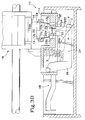
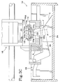
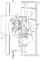
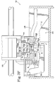
- Figs. 3A through 3F are sectional illustrations corresponding generally with Fig. 1 and showing various phases of the operation of the invented priming cap and system.
- Fig. 4 is an alternative embodiment of the invention featuring a dual printhead capping and priming system in a rotatable, multi-service station.
- Fig. 1 is a front elevation of the invented priming system in its preferred embodiment, indicated at 10.
- system 10 includes an ink-jet printhead-priming cap 12 mounted for vertical reciprocation on a sled 14 beneath an ink-jet printhead 16 that typically is mounted for horizontal reciprocation on a carriage including a carriage rod, indicated generally at 18.
- cap 12 preferably includes a first, e.g. upper, expanse 12 a including a peripheral lip region 12 aa for sealingly engaging an ink-jet printhead, with first expanse 12 a also preferably having formed therein an aperture 12 b through which ink can be drawn.
- Cap 12 also preferably includes flexible sidewalls such as rectilinearly extending sidewalls 12 c , 12 d , 12 e , 12 f connected in a first, e.g. upper, region thereof with, and extending from, first expanse 12 a , with the sidewalls extending at least substantially continuously around a perimeter of the first expanse, as shown in Fig. 1.
- Cap 12 also preferably includes a second, e.g. lower, expanse 12 g connected with a second, e.g. lower, region of sidewalls 12 c , 12 d , 12 e , 12 f to form a substantially sealed chamber of nominal volume into which ink can be drawn, such chamber being indicated in Fig. 1 generally at 20.
- a second, e.g. lower, expanse 12 g connected with a second, e.g. lower, region of sidewalls 12 c , 12 d , 12 e , 12 f to form a substantially sealed chamber of nominal volume into which ink can be drawn, such chamber being indicated in Fig. 1 generally at 20.
- second expanse 12 g has generally centrally located therein structure, e.g. a thickened central region 12 ga having a hole 12 gaa formed therein, for matingly, e.g. yieldably conformingly, engaging a piston, or piston member, 22.
- a piston or piston member 22.
- alternative means for engaging piston 22 and first expanse 12 a of cap 12 may be used.
- flexible sidewalls 12 c , 12 d , 12 e , 12 f enable the volume of chamber 20 alternately to be decreased and increased by piston action, thereby to prime printhead 16 by producing relatively reduced pressure in the chamber to draw ink thereinto from the printhead with the printhead sealingly engaged by lip region 12 aa of first expanse 12 a .
- flexible sidewalls 12 c , 12 d , 12 e , 12 f collectively will be referred to herein as a diaphragm, and more specifically in the context of the preferred embodiment of the invention as a rolling diaphragm, for reasons that will be apparent to persons skilled in the art.
- any suitable material e.g. a pliable polymeric or other elastomeric material.
- central region 12 ga of second expanse 12 g is generally congruent with the piston member-mating structure described above is thicker than a peripheral, or annular, region 12 gb therearound.
- the thickness of the second region of sidewalls 12 c , 12 d , 12 e , 12 f preferably is substantially the same as the thickness of second expanse 12 g in such peripheral region 12 gb , and the inner surfaces of the sidewalls preferably continuously smoothly connect with this peripheral region of the second expanse.
- one of the first and second expanses is of lesser extent in its two dimensions than the other in its two corresponding dimensions such that connecting sidewalls 12 c , 12 d , 12 e , 12 f , are inclined therebetween.
- a region of second expanse 12 g around the inside of hole 12 gaa formed therein that forms the above-described piston member-mating structure includes a recessed annular shoulder for seating an enlarged terminal region 22 a of a terminal end 22 b of piston 22 that extends at least partway through hole 12 gaa .
- invented tubeless ink-jet carriage-mounted printhead priming system 10 may be described as including 1) piston member 22 having distal end 22 b ; 2) a first drive mechanism, indicated generally at 24, for reciprocating distal end 22 b of piston member 22 generally along a predefined axis such as axis A; and 3) a generally vertically reciprocable cap 12, cap 12 having an upper region 12 a , preferably including lip region 12 aa , located along axis A for sealingly engaging printhead 16 in a first predefined position of cap 12 relative to a horizontally reciprocal carriage 18 that mounts such printhead 16 (e.g. a position such as that shown in Fig. 1).
- cap 12 has a receptacle, also generally indicated at 20, formed therewith for receiving ink droplets introduced thereinto from the printhead.
- first drive mechanism 24 in accordance with the first preferred embodiment of the invention takes the form of a pivotal member, or lever, or rocker arm, 26 having operatively connected on a distal end 26 a thereof piston member 22, with a pinned second end 26 b defining an axis for pivotal reciprocation of arm 26 thereabout by any suitable drive mechanism (such as a lifter, which in a first preferred embodiment takes the form of a cam C and a cam follower F arrangement of a cap-mounting sled and a sled mounting base, and a return spring S) to produce generally vertical reciprocation of piston member 22 in synchronization with horizontal reciprocation of the printer's carriage.
- a lifter which in a first preferred embodiment takes the form of a cam C and a cam follower F arrangement of a cap-mounting sled and a sled mounting base, and a return spring S
- any suitable drive mechanism such as a lifter, which in a first preferred embodiment takes the form of a cam C and a cam follower F
- receptacle 20 preferably has a diaphragm located along axis A defining a lower region of the receptacle, with the diaphragm having on a lower surface thereof structure operatively engaging piston member 22.
- the diaphragm is flexed by generally vertical reciprocation of piston member 22 in predefined synchronization with carriage 18, with cap 12 in sealing engagement with the printhead to prime the same, thereby to cause ink droplets to exit the printhead and to be collected in the receptacle.
- a second drive mechanism indicated generally at 28, is provided for lowering cap 12 to a second predefined position below the first predefined position in predefined synchronization with reciprocation of piston member 22 such that cap 12 sealingly engages printhead 16 only during a downstroke of the piston member.
- second drive mechanism 28 operatively coupled with second drive mechanism 28 is moveable sled 14 mounting invented cap 12, wherein sled 14 is vertically reciprocated in predetermined synchronism with lateral reciprocation of carriage 18. In this embodiment of invented system 10, lowering of sled 14 effects lowering of cap 12 to such second predefined position.
- second drive mechanism in the first preferred embodiment described and illustrated herein may take the form of the cam and cam follower arrangement suggested in Figs. 1 and 3A through 3F constructed, for example, in accordance with the teachings of my co-pending U.S. Patent Application Serial No. 07/949,197 entitled “Ink-jet Printhead Capping and Wiping Method and Apparatus", which was filed September 21, 1992 and which is commonly owned herewith (European Patent Appln. No. 93306983.3 published as EP-A-0 589 582).
- second drive mechanism 28 may take the form of a stepper motor capable of alternately raising and lowering sled 14 responsive to drive signals produced by the printer's controller.
- sled 14 may be reciprocally raised and lowered by any suitable means.
- Fig. 2 corresponds with Fig. 1, but represents invented system 10 in side elevational view.
- chamber or receptacle 20 is reduced from a maximum to a minimum volume, and sidewalls 12 c , 12 d , 12 e , 12 f are rolled, or substantially and smoothly folded back on themselves, such that the sealing engagement of lip region 12 aa of expanse 12 a with printhead 16 during a downstroke of piston 22 produces a vacuum within chamber 20.
- piston 22 returns from its position shown in Fig. 3C, for example, to its position shown in Fig.
- ink-jet printhead 16 will be primed, and ink droplets will be forced to exit the pens' orifices, to pass through hole 12 ab in expanse 12 a and to drop into chamber or receptacle 20. In this way, then, ink-jet printhead 16 is primed without the need for a tube for each included pen leading from a corresponding priming structure to a common receptacle located remote therefrom, as heretofore have been required.
- Figs. 3A through 3F illustrate the operation of system 10 in various phases of its operation, in somewhat simplified form.
- Fig. 3A shows system 10 in an initial, or start, phase of operation in which sled 14 is lowered and invented priming cap 12 is uncompressed such that its chamber is of maximum volume.
- Fig. 3B shows system 10 in a later phase of operation in which sled 14 remains in its lowered position and in which compression of cap 12 begins.
- Fig. 3C shows system 10 in a still later phase of operation in which sled 14 yet is lowered (and has been moved to the left by carriage 18, and the second end 26 b of lever 26 has climbed the sled's ramped cam surface) and in which cap 12 is fully compressed such that its chamber is of minimal volume.
- Fig. 3A shows system 10 in an initial, or start, phase of operation in which sled 14 is lowered and invented priming cap 12 is uncompressed such that its chamber is of maximum volume.
- Fig. 3B shows system 10 in
- FIG. 3D shows system 10 in a yet later phase of operation in which capping begins by raising sled 14 with cap 12 yet fully compressed but without contact between its lip region 12 aa and printhead 16.
- Fig. 3E shows system 10 in a priming phase of operation in which previously fully compressed cap 12 sealingly engages printhead 16 and during which ink is drawn from ink-jet printhead 16 by progressive decompression of the cap. It is noted that lever 26 controllably is returning piston 22 to its initial, unelevated position by the cooperative action of spring S, cam C and follower F.
- capping refers to the sealing engagement with printhead 16 of lip region 12 aa of cap 12, rather than to conventional capping of a printhead when it is not in use, which conventional capping requires printhead venting to ambient pressure.
- invented priming cap and system are compatible with such conventional capping of printheads for such purpose, while also providing the unique printhead-priming advantages described herein.
- Fig. 3F shows system 10 in a final phase of operation in which priming by cap 12 is complete. It is noted that lever 26 has returned fully to its initial position, representing completion of a downstroke of first end 22 a of operatively connected piston member 22 and decompression of cap 12. Importantly, it will be appreciated by contrasting Figs. 3D, 3E and 3F that printhead 16 is not capped during an upstroke of piston member 22 during which cap 12 is compressed, but instead is capped preferably simultaneously with, or slightly after, the beginning of the downstroke of piston member 22. In this way, no head is produced in printhead 16 and only a vacuum is produced therein at the beginning of the priming step facilitated by invented priming cap 12 and system 10 described herein. This avoids undesirable production of a positive pressurization of printhead 16 that might damage the printhead.
- Fig. 4 illustrates an alternative embodiment of invented system 10 in which a priming cap is mounted for rotation on a multi-service station including an ink blotter for removing accumulated ink therefrom.
- a rotatable member 30 mounts cap 12 for selective sealing engagement of printhead 16 thereby when member 30 is rotated to a first predefined position of proximity between cap 12 and printhead 16 (e.g. the position shown in Fig. 4).
- Other service stations including, for example, a conventional cap 32 and a conventional wiper 34, may be provided on member 30. Shown also in Fig.
- blotter 36 is a blotter 36 disposed adjacent the periphery of rotatable member 30 in arcuately spaced relationship with printhead 16 for blotting ink collected in receptacle 20 when rotatable member 30 is rotated to a predefined second position of proximity between cap 12 and such blotter 36.
- this second predefined position corresponds to the location of blotter 36 shown in Fig. 4, and that rotatable member 30 may of course be rotated, either unidirectionally or bidirectionally, by any suitable means such as a stepper motor under the control of the ink-jet printer's controller.
- the capacity of invented priming cap 12 is 500-1000 typical priming cycles, it is convenient to blot priming cap 12 after each priming cycle, as by use of blotter 36 of the alternative Fig. 4 embodiment.
- priming cap 12 may be designed at somewhat greater complexity to provide a vacuum seal with printhead during the relatively short-term priming cycle, as taught herein, and to provide a vent to ambient of the printhead during the relatively long-term capping cycle, as is known.
- the invented priming cap and system eliminate the need for tubes extending between a common diaphragm pump and one or more primer mechanisms corresponding with one or more printheads, and between such one or more primer mechanisms and a common ink receptacle.
- ink-jet printhead priming is accomplished for one or more printheads without tubes and without a multiplicity of complex priming assemblies for the one or more printheads.
- the invented priming cap and system are relatively easily and inexpensively manufactured and maintained in singular or plural ink-jet printhead printers, with the simplest of drive mechanisms including, for example, a cam and cam follower arrangement of a sled driven by the printer's existing carriage motor, a lever and a spring.
- the cap itself inexpensively may be manufactured by the use of relatively inexpensive tools such as injection molds.
- the priming of one or more printheads is accomplished in a short cycle time, thus taking the printer off-line for priming only minimally.
Landscapes
- Ink Jet (AREA)
Claims (10)
- Système d'amorçage sans tube de tête d'impression à jet d'encre montée sur un chariot (10), comprenant :un organe formant piston (22) ayant une extrémité distale (22b);un premier mécanisme d'entraínement (24) pour faire alterner ladite extrémité distale (22b) dudit organe formant piston (22) généralement le long d'un axe prédéfini (A);un couvercle pouvant être déplacé en va-et-vient généralement verticalement (12), ledit couvercle (12) ayant une région supérieure (12aa) située le long dudit axe (A) pour venir en prise de manière étanche avec une tête d'impression (16) dans une première position prédéfinie dudit couvercle (12) par rapport à un chariot alternatif horizontal (18) sur lequel est montée ladite tête d'impression (16), ledit couvercle (12) ayant une cavité (20) formée dans celui-ci, destinée à recevoir des gouttelettes d'encre introduites dans celle-ci depuis la tête d'impression (16); et
ladite cavité (20) ayant un diaphragme situé le long de l'axe (A) et définissant une région inférieure de ladite cavité (20), ledit diaphragme ayant sur une surface inférieure de celui-ci une structure (12ga) venant en prise de manière fonctionnelle avec ladite extrémité distale (22b) dudit organe formant piston (22),
ledit diaphragme étant plié par l'alternance généralement verticale de ladite extrémité distale (22b) dudit organe formant piston (22) en synchronisation prédéfinie avec ce chariot (18); ledit couvercle (12) étant en prise de manière étanche avec la tête d'impression (16) pour amorcer la tête d'impression (16) provoquant ainsi la sortie de gouttelettes d'encre de la tête d'impression (16) et leur récupération dans ladite cavité (20). - Système (10) selon la revendication 1, comprenant en outre un deuxième mécanisme d'entraínement (28) pour abaisser ledit couvercle (12) dans une deuxième position prédéfinie au-dessous de ladite première position prédéfinie en synchronisation prédéfinie avec le mouvement alternatif dudit organe formant piston (22) de façon que ledit couvercle (12) ne vienne en prise de manière étanche avec la tête d'impression (16) que pendant une course inférieure dudit organe formant piston (22).
- Système (10) selon la revendication 2, comprenant en outre un traíneau mobile (14) couplé fonctionnellement audit deuxième mécanisme d'entraínement (28) et recevant ledit couvercle (12), dans lequel l'abaissement dudit traíneau (14) effectue un tel abaissement dudit couvercle (12).
- Système (10) selon la revendication 2, comprenant en outre un organe rotatif (30) recevant ledit couvercle (12) pour que la tête d'impression (16) vienne ainsi en prise sélective de manière étanche lorsque ledit organe rotatif (30) est tourné dans une première position prédéfinie de proximité entre ledit couvercle (12) et ladite tête d'impression (16).
- Système (10) selon la revendication 4, comprenant en outre un buvard (36) disposé de manière adjacente à la périphérie dudit organe rotatif (30), en relation espacée de manière courbe avec cette tête d'impression (16) pour absorber l'encre recueillie dans ladite cavité (20) lorsque ledit organe rotatif (30) est mis en rotation vers une deuxième position de proximité prédéfinie entre ledit couvercle (12) et ce buvard (36).
- Système (10) selon la revendication 1, dans lequel ledit couvercle (12) comporte un prolongement supérieur (12a) comportant en une extension supérieure de celle-ci une région formant lèvre periphérique (12aa) pour venir en prise de manière étanche avec ladite tête d'impression (16) de façon à recouvrir ainsi celle-ci, ledit prolongement supérieur (12a) comportant, formée dans celui-ci, une ouverture (12b) à travers laquelle de l'encre peut être extraite, dans lequel ledit couvercle (12) comporte en outre des parois latérales souples (12c, d, e, f) connectées à, et s'étendant vers le bas depuis, dudit prolongement supérieur (12a), lesdites parois latérales (12c, d, e, f) s'étendant de manière continue autour d'un périmètre dudit prolongement supérieur (12a) et dans lequel ledit couvercle (12) comprend en outre un prolongement inférieur (12g) connecté à une extension inférieure desdites parois latérales (12c, d, e, f) pour former une chambre sensiblement étanche (20) d'un certain volume nominal dans lequel de l'encre peut être extraite, ledit prolongement inférieur (12g) comportant, généralement située de façon centrale dans une surface de fond de celle-ci, une structure (12ga, 12gaa) pour venir en prise par accouplement avec ledit organe formant piston (22), lesdites parois latérales souples (12c, d, e, f) permettant au volume de ladite chambre (20) d'être alternativement diminué et augmenté par action de piston, de façon à amorcer la tête d'impression en produisant une pression relativement réduite dans ladite chambre (20) pour extraire l'encre dans celle-ci depuis cette tête d'impression (16), cette tête d'impression (16) étant en prise de manière étanche avec ladite région formant lèvre (12aa).
- Système (10) selon la revendication 6, dans lequel lesdits prolongements supérieur et inférieur (12a, 12g) et lesdites parois latérales (12c, d, e, f) dudit couvercle (12) sont moulées dd'un seul tenant à partir d'un matériau polymère pliable.
- Système (10) selon la revendication 7, dans lequel une région centrale (12ga) dudit prolongement inférieur (12g) généralement conforme à ladite structure (12ga, 12gaa) est plus épaisse qu'une région périphérique (12gb) autour de celle-ci.
- Système (10) selon la revendication 8, dans lequel l'épaisseur dudit prolongement inférieur desdites parois latérales (12c, d, e, f) est sensiblement la même que l'épaisseur dudit prolongement inférieur (12g) de ladite région périphérique (12gb) et dans lequel les surfaces internes desdites parois latérales (12c, d, e, f) sont connectées régulièrement à ladite région périphérique (12gb) dudit prolongement inférieur (12g).
- Système (10) selon la revendication 9, dans lequel ledit prolongement inférieur (12g) est d'une étendue inférieure en deux dimensions à celle dudit prolongement supérieur (12a) et dans lequel lesdites parois latérales (12c, d, e, f) sont inclinées entre ceux-ci de manière à former un diaphragme rotatif.
Applications Claiming Priority (2)
| Application Number | Priority Date | Filing Date | Title |
|---|---|---|---|
| US94634 | 1993-07-19 | ||
| US08/094,634 US5534896A (en) | 1993-07-19 | 1993-07-19 | Tubeless ink-jet printer priming cap system and method |
Publications (3)
| Publication Number | Publication Date |
|---|---|
| EP0635371A2 EP0635371A2 (fr) | 1995-01-25 |
| EP0635371A3 EP0635371A3 (fr) | 1995-08-16 |
| EP0635371B1 true EP0635371B1 (fr) | 1998-05-27 |
Family
ID=22246281
Family Applications (1)
| Application Number | Title | Priority Date | Filing Date |
|---|---|---|---|
| EP94304872A Expired - Lifetime EP0635371B1 (fr) | 1993-07-19 | 1994-07-04 | Système et calotte sans tube d'amorcage d'une imprimante à jet d'encre |
Country Status (6)
| Country | Link |
|---|---|
| US (1) | US5534896A (fr) |
| EP (1) | EP0635371B1 (fr) |
| JP (1) | JP3588145B2 (fr) |
| KR (1) | KR100333216B1 (fr) |
| CA (1) | CA2111414C (fr) |
| DE (1) | DE69410544T2 (fr) |
Families Citing this family (48)
| Publication number | Priority date | Publication date | Assignee | Title |
|---|---|---|---|---|
| US5714991A (en) * | 1995-03-03 | 1998-02-03 | Hewlett-Packard Company | Rotary priming system for inkjet printheads |
| US5793389A (en) * | 1995-09-25 | 1998-08-11 | Hewlett-Packard Company | Fluid purge apparatus and method for ink jet printer pen |
| JPH09141884A (ja) * | 1995-11-16 | 1997-06-03 | Brother Ind Ltd | インクジェットプリンタ |
| KR0131090Y1 (ko) * | 1995-12-12 | 1999-03-30 | 김광호 | 잉크제트 프린터용 헤드의 서어비스스테이션 장치 |
| US5801726A (en) * | 1995-12-22 | 1998-09-01 | Calcomp Inc. | Service station support bracket for printers |
| EP1167041B1 (fr) * | 1996-11-22 | 2004-03-03 | Seiko Epson Corporation | Appareil d'enregistrement à jet d'encre |
| US6007318A (en) | 1996-12-20 | 1999-12-28 | Z Corporation | Method and apparatus for prototyping a three-dimensional object |
| US7037382B2 (en) | 1996-12-20 | 2006-05-02 | Z Corporation | Three-dimensional printer |
| US5969711A (en) * | 1997-03-25 | 1999-10-19 | Bennethum Computer Systems | Method for creating an electronic document |
| US6309044B1 (en) * | 1998-04-10 | 2001-10-30 | Hewlett-Packard Company | Two stage print cartridge capping technique |
| US6220689B1 (en) * | 1998-06-24 | 2001-04-24 | Hewlett-Packard Company | Unitary capping system for multiple inkjet printheads |
| US6168259B1 (en) | 1998-10-09 | 2001-01-02 | Eastman Kodak Company | Printer for forming a full-width image on a receiver exclusive of a transverse side of the receiver, and method of assembling the printer |
| US6183057B1 (en) * | 1998-12-04 | 2001-02-06 | Eastman Kodak Company | Self-cleaning ink jet printer having ultrasonics with reverse flow and method of assembling same |
| US6382766B1 (en) * | 2000-04-20 | 2002-05-07 | Samsung Electronics Co., Ltd. | Maintenance apparatus for ink nozzle of image forming apparatus |
| US6517185B1 (en) | 2001-03-09 | 2003-02-11 | Lexmark International, Inc. | Low force ink jet printhead capping system |
| US6693579B2 (en) | 2001-08-01 | 2004-02-17 | Lexmark International, Inc. | Method to improve sealing of ink jet printhead purge mechanism to printhead |
| US6905189B1 (en) | 2002-05-16 | 2005-06-14 | Vutek, Inc. | Wet capping tray for ink jet printheads |
| US6773088B2 (en) * | 2002-11-15 | 2004-08-10 | Lexmark International, Inc. | Double lipped printhead maintenance cap |
| US6755509B2 (en) * | 2002-11-23 | 2004-06-29 | Silverbrook Research Pty Ltd | Thermal ink jet printhead with suspended beam heater |
| WO2004106041A2 (fr) * | 2003-05-23 | 2004-12-09 | Z Corporation | Appareil et proceces pour impression 3d |
| US6817695B1 (en) | 2003-06-03 | 2004-11-16 | Lexmark International, Inc. | Printhead capping assembly |
| JP4085275B2 (ja) | 2003-07-17 | 2008-05-14 | 船井電機株式会社 | インクジェット記録装置およびキャッピング装置 |
| US7021741B2 (en) * | 2003-11-21 | 2006-04-04 | Lexmark International, Inc. | Printhead cap assembly for an ink jet printer |
| US20050280185A1 (en) * | 2004-04-02 | 2005-12-22 | Z Corporation | Methods and apparatus for 3D printing |
| US7387359B2 (en) * | 2004-09-21 | 2008-06-17 | Z Corporation | Apparatus and methods for servicing 3D printers |
| US7284819B2 (en) * | 2004-12-06 | 2007-10-23 | Silverbrook Research Pty Ltd | Inkjet printer with turret mounted capping/purging mechanism |
| US6984017B1 (en) * | 2004-12-06 | 2006-01-10 | Silverbrook Research Pty Ltd | Inkjet printer incorporating a reel-to-reel flexible capping member |
| US7328968B2 (en) * | 2004-12-06 | 2008-02-12 | Silverbrook Research Pty Ltd | Inkjet printer with simplex printhead and capping/purging mechanism |
| US7270393B2 (en) * | 2004-12-06 | 2007-09-18 | Silverbrook Research Pty Ltd | Inkjet printer incorporating a spool-fed flexible capping member |
| US7347526B2 (en) * | 2004-12-06 | 2008-03-25 | Silverbrook Research Pty Ltd | Capping member for inkjet printer |
| US7258416B2 (en) * | 2004-12-06 | 2007-08-21 | Silverbrook Research Pty Ltd | Inkjet printer with pivotal capping member |
| US7364256B2 (en) * | 2004-12-06 | 2008-04-29 | Silverbrook Research Pty Ltd | Inkjet printer with capping mechanism |
| US7334864B2 (en) * | 2004-12-06 | 2008-02-26 | Silverbrook Research Pty Ltd | Inkjet printer with arcuately moveable duplex printhead assembly and capping system |
| US7273263B2 (en) * | 2004-12-06 | 2007-09-25 | Silverbrook Research Pty Ltd | Inkjet printer incorporating a flexible capping member |
| JP5265341B2 (ja) * | 2005-04-21 | 2013-08-14 | インダストリアル リサーチ リミテッド | 圧力波発生器 |
| US8984898B2 (en) | 2005-04-21 | 2015-03-24 | Industrial Research Limited | Cryogenic refrigerator system with pressure wave generator |
| US7971991B2 (en) | 2006-05-26 | 2011-07-05 | Z Corporation | Apparatus and methods for handling materials in a 3-D printer |
| JP5183121B2 (ja) * | 2007-08-10 | 2013-04-17 | キヤノン株式会社 | インクジェット記録装置 |
| CN101879813B (zh) * | 2009-05-06 | 2012-02-01 | 金宝电子工业股份有限公司 | 喷墨打印机 |
| US8714697B2 (en) | 2012-08-28 | 2014-05-06 | Eastman Kodak Company | Pumping cap for applying suction to printhead |
| US8662632B1 (en) | 2012-08-28 | 2014-03-04 | Eastman Kodak Company | Method of maintaining an inkjet printhead |
| JP6187364B2 (ja) * | 2014-03-31 | 2017-08-30 | ブラザー工業株式会社 | 印刷装置 |
| CN107073985B (zh) * | 2015-01-29 | 2019-09-10 | 惠普发展公司,有限责任合伙企业 | 标识已灌注的打印头 |
| JP6962115B2 (ja) * | 2017-09-29 | 2021-11-05 | ブラザー工業株式会社 | 液体吐出装置 |
| WO2019212464A1 (fr) * | 2018-04-30 | 2019-11-07 | Hewlett-Packard Development Company, L.P. | Entretien de têtes d'impression |
| US10518537B1 (en) * | 2018-11-29 | 2019-12-31 | Xerox Corporation | System and method for attenuating the drying of ink from a printhead |
| CN113165406B (zh) | 2018-12-20 | 2023-07-28 | 惠普发展公司,有限责任合伙企业 | 打印系统 |
| US10919299B1 (en) * | 2019-09-05 | 2021-02-16 | Xerox Corporation | System and method to counteract the drying of aqueous inks in a printhead |
Family Cites Families (23)
| Publication number | Priority date | Publication date | Assignee | Title |
|---|---|---|---|---|
| US3820445A (en) * | 1972-04-14 | 1974-06-28 | W Klink | Prime mover of the radial engine type |
| ZA733118B (en) * | 1973-05-08 | 1975-01-29 | Phoenix Valve Mfg Ltd | Fluid flow control valve |
| US4162501A (en) * | 1977-08-08 | 1979-07-24 | Silonics, Inc. | Ink supply system for an ink jet printer |
| US4272052A (en) * | 1979-05-07 | 1981-06-09 | Zurn Industries, Inc. | Flush valves |
| DE3051198C2 (de) * | 1979-10-23 | 1996-11-14 | Canon Kk | Abdeck- und Absaugvorrichtung für Tintenstrahlschreiber |
| FR2478958A1 (fr) * | 1980-04-01 | 1981-10-02 | Decoufle | Dispositif d'alimentation en encre des appareils d'imprimerie pour machines a confectionner les cigarettes |
| DE3018687C2 (de) * | 1980-05-16 | 1986-10-30 | J. Wagner Gmbh, 7990 Friedrichshafen | Membran für Hochdruckförderpumpen, Kompressoren oder dgl. |
| JPS59209876A (ja) * | 1983-05-14 | 1984-11-28 | Konishiroku Photo Ind Co Ltd | 液体供給装置 |
| US4488702A (en) * | 1983-09-29 | 1984-12-18 | Lapeyre James M | Rolling diaphragm metering valve |
| USRE32880E (en) * | 1985-10-15 | 1989-02-28 | The Laitram Corporation | Rolling diaphragm metering valve |
| US4872813A (en) * | 1987-12-01 | 1989-10-10 | Pacesetter Infusion, Ltd. | Disposable cassette for a medication infusion system |
| SG47854A1 (en) * | 1988-09-07 | 1998-04-17 | Seiko Epson Corp | Ink jet printer sealing method and apparatus |
| US5252993A (en) * | 1988-09-07 | 1993-10-12 | Seiko Epson Corporation | Capping apparatus for an ink jet printer |
| JPH02167752A (ja) * | 1988-12-21 | 1990-06-28 | Canon Inc | インクジェット記録装置 |
| DE69029780T2 (de) * | 1989-08-31 | 1997-07-10 | Canon Kk | Absaug-Regeneriervorrichtung für ein Tintenstrahlaufzeichnungsgerät |
| US5108373A (en) * | 1989-09-25 | 1992-04-28 | Baxter International Inc. | Intravenous metering device |
| DE69124271T2 (de) * | 1990-02-13 | 1997-08-14 | Canon Kk | Farbrückgewinnungsvorrichtung bei einer Farbstrahlaufzeichnungsvorrichtung |
| US5051761A (en) * | 1990-05-09 | 1991-09-24 | Xerox Corporation | Ink jet printer having a paper handling and maintenance station assembly |
| US5260724A (en) * | 1991-01-09 | 1993-11-09 | Seiko Epson Corporation | Capping device for ink jet printer |
| US5151715A (en) * | 1991-07-30 | 1992-09-29 | Hewlett-Packard Company | Printhead wiper for ink-jet printers |
| US5517219A (en) * | 1992-01-16 | 1996-05-14 | Canon Kabushiki Kaisha | Ink jet recording apparatus having an improved capping mechanism |
| JPH05278223A (ja) * | 1992-03-31 | 1993-10-26 | Fuji Xerox Co Ltd | インクジェット記録ヘッド用キャップ装置 |
| JPH06218935A (ja) * | 1993-01-25 | 1994-08-09 | Fuji Xerox Co Ltd | インクジェット記録装置 |
-
1993
- 1993-07-19 US US08/094,634 patent/US5534896A/en not_active Expired - Lifetime
- 1993-12-14 CA CA002111414A patent/CA2111414C/fr not_active Expired - Fee Related
-
1994
- 1994-07-04 DE DE69410544T patent/DE69410544T2/de not_active Expired - Lifetime
- 1994-07-04 EP EP94304872A patent/EP0635371B1/fr not_active Expired - Lifetime
- 1994-07-18 JP JP18784394A patent/JP3588145B2/ja not_active Expired - Fee Related
- 1994-07-18 KR KR1019940017227A patent/KR100333216B1/ko not_active Expired - Fee Related
Also Published As
| Publication number | Publication date |
|---|---|
| DE69410544D1 (de) | 1998-07-02 |
| KR100333216B1 (ko) | 2002-09-04 |
| JP3588145B2 (ja) | 2004-11-10 |
| DE69410544T2 (de) | 1998-09-17 |
| EP0635371A3 (fr) | 1995-08-16 |
| US5534896A (en) | 1996-07-09 |
| EP0635371A2 (fr) | 1995-01-25 |
| KR950002992A (ko) | 1995-02-16 |
| CA2111414A1 (fr) | 1995-01-20 |
| CA2111414C (fr) | 2004-09-21 |
| JPH0740541A (ja) | 1995-02-10 |
Similar Documents
| Publication | Publication Date | Title |
|---|---|---|
| US5534896A (en) | Tubeless ink-jet printer priming cap system and method | |
| US5440331A (en) | Printhead servicing apparatus | |
| US5563638A (en) | Ink-jet printhead capping and wiping method and apparatus | |
| JP2879608B2 (ja) | メンテナンスステーションおよびその駆動方法 | |
| US5434605A (en) | Automatic failure recovery method and system for ink-jet printheads | |
| US5883645A (en) | Recovery mechanism and an ink jet recording apparatus using the recovery mechanism | |
| US20080024550A1 (en) | Maintenance device for liquid ejection head | |
| US8328324B2 (en) | Maintenance device for liquid ejection head | |
| US8322818B2 (en) | Maintenance device for liquid ejection head and liquid ejection apparatus | |
| EP0605121B1 (fr) | Procédé et appareil pour l'élimination d'encre perdue dans une station de recouvrement | |
| EP1080915B1 (fr) | Dispositif de tête à jet de liquide | |
| US7837292B2 (en) | Liquid ejection apparatus | |
| CA2438699C (fr) | Comprise et systeme d'amorcage pour imprimante a jet d'encre sans tubes | |
| US7866790B2 (en) | Maintenance device for liquid ejection head and liquid ejection apparatus | |
| EP1080929A2 (fr) | Chariot, imprimante, tête d'éjection de liquide et sa méthode d'insertion et de positionnement | |
| JP3575177B2 (ja) | インクジェット方式の画像形成装置 | |
| US7360863B2 (en) | Printing apparatus with a priming device | |
| JP3175610B2 (ja) | インクジェット方式の画像形成装置及びそれに用いられるインク吸引ポンプ | |
| JP3557805B2 (ja) | インクジェット方式の画像形成装置及びそれに用いられるインク吸引ポンプ | |
| CA2125196C (fr) | Elimination de l'encre usee dans une imprimante | |
| JP2000238276A (ja) | インクジェット記録装置 | |
| JP2003191501A (ja) | インクジェット記録装置 | |
| JP2005271237A (ja) | インクジェット記録装置 | |
| JPH0615833A (ja) | インクジェット記録装置 | |
| JPWO1994013488A1 (ja) | メンテナンスステーションおよびその駆動方法 |
Legal Events
| Date | Code | Title | Description |
|---|---|---|---|
| PUAI | Public reference made under article 153(3) epc to a published international application that has entered the european phase |
Free format text: ORIGINAL CODE: 0009012 |
|
| AK | Designated contracting states |
Kind code of ref document: A2 Designated state(s): DE FR GB IT |
|
| PUAL | Search report despatched |
Free format text: ORIGINAL CODE: 0009013 |
|
| AK | Designated contracting states |
Kind code of ref document: A3 Designated state(s): DE FR GB IT |
|
| 17P | Request for examination filed |
Effective date: 19960119 |
|
| GRAG | Despatch of communication of intention to grant |
Free format text: ORIGINAL CODE: EPIDOS AGRA |
|
| 17Q | First examination report despatched |
Effective date: 19970929 |
|
| GRAG | Despatch of communication of intention to grant |
Free format text: ORIGINAL CODE: EPIDOS AGRA |
|
| GRAH | Despatch of communication of intention to grant a patent |
Free format text: ORIGINAL CODE: EPIDOS IGRA |
|
| GRAH | Despatch of communication of intention to grant a patent |
Free format text: ORIGINAL CODE: EPIDOS IGRA |
|
| GRAA | (expected) grant |
Free format text: ORIGINAL CODE: 0009210 |
|
| ITF | It: translation for a ep patent filed | ||
| AK | Designated contracting states |
Kind code of ref document: B1 Designated state(s): DE FR GB IT |
|
| REF | Corresponds to: |
Ref document number: 69410544 Country of ref document: DE Date of ref document: 19980702 |
|
| ET | Fr: translation filed | ||
| PLBE | No opposition filed within time limit |
Free format text: ORIGINAL CODE: 0009261 |
|
| STAA | Information on the status of an ep patent application or granted ep patent |
Free format text: STATUS: NO OPPOSITION FILED WITHIN TIME LIMIT |
|
| 26N | No opposition filed | ||
| REG | Reference to a national code |
Ref country code: GB Ref legal event code: 732E |
|
| REG | Reference to a national code |
Ref country code: FR Ref legal event code: TP |
|
| REG | Reference to a national code |
Ref country code: GB Ref legal event code: IF02 |
|
| PGFP | Annual fee paid to national office [announced via postgrant information from national office to epo] |
Ref country code: GB Payment date: 20070727 Year of fee payment: 14 |
|
| PGFP | Annual fee paid to national office [announced via postgrant information from national office to epo] |
Ref country code: IT Payment date: 20070727 Year of fee payment: 14 |
|
| PGFP | Annual fee paid to national office [announced via postgrant information from national office to epo] |
Ref country code: FR Payment date: 20070717 Year of fee payment: 14 |
|
| GBPC | Gb: european patent ceased through non-payment of renewal fee |
Effective date: 20080704 |
|
| REG | Reference to a national code |
Ref country code: FR Ref legal event code: ST Effective date: 20090331 |
|
| PG25 | Lapsed in a contracting state [announced via postgrant information from national office to epo] |
Ref country code: GB Free format text: LAPSE BECAUSE OF NON-PAYMENT OF DUE FEES Effective date: 20080704 |
|
| PG25 | Lapsed in a contracting state [announced via postgrant information from national office to epo] |
Ref country code: IT Free format text: LAPSE BECAUSE OF NON-PAYMENT OF DUE FEES Effective date: 20080704 Ref country code: FR Free format text: LAPSE BECAUSE OF NON-PAYMENT OF DUE FEES Effective date: 20080731 |
|
| PGFP | Annual fee paid to national office [announced via postgrant information from national office to epo] |
Ref country code: DE Payment date: 20130621 Year of fee payment: 20 |
|
| REG | Reference to a national code |
Ref country code: DE Ref legal event code: R071 Ref document number: 69410544 Country of ref document: DE |
|
| PG25 | Lapsed in a contracting state [announced via postgrant information from national office to epo] |
Ref country code: DE Free format text: LAPSE BECAUSE OF EXPIRATION OF PROTECTION Effective date: 20140705 |