EP0635971A2 - Gerät und Verfahren zur Umwandlung erweiterter Farbe zu Farbe - Google Patents
Gerät und Verfahren zur Umwandlung erweiterter Farbe zu Farbe Download PDFInfo
- Publication number
- EP0635971A2 EP0635971A2 EP94305298A EP94305298A EP0635971A2 EP 0635971 A2 EP0635971 A2 EP 0635971A2 EP 94305298 A EP94305298 A EP 94305298A EP 94305298 A EP94305298 A EP 94305298A EP 0635971 A2 EP0635971 A2 EP 0635971A2
- Authority
- EP
- European Patent Office
- Prior art keywords
- value
- source
- color
- destination
- chroma
- Prior art date
- Legal status (The legal status is an assumption and is not a legal conclusion. Google has not performed a legal analysis and makes no representation as to the accuracy of the status listed.)
- Granted
Links
Images





Classifications
-
- H—ELECTRICITY
- H04—ELECTRIC COMMUNICATION TECHNIQUE
- H04N—PICTORIAL COMMUNICATION, e.g. TELEVISION
- H04N1/00—Scanning, transmission or reproduction of documents or the like, e.g. facsimile transmission; Details thereof
- H04N1/40—Picture signal circuits
- H04N1/40012—Conversion of colour to monochrome
-
- H—ELECTRICITY
- H04—ELECTRIC COMMUNICATION TECHNIQUE
- H04N—PICTORIAL COMMUNICATION, e.g. TELEVISION
- H04N1/00—Scanning, transmission or reproduction of documents or the like, e.g. facsimile transmission; Details thereof
- H04N1/46—Colour picture communication systems
- H04N1/465—Conversion of monochrome to colour
-
- H—ELECTRICITY
- H04—ELECTRIC COMMUNICATION TECHNIQUE
- H04N—PICTORIAL COMMUNICATION, e.g. TELEVISION
- H04N1/00—Scanning, transmission or reproduction of documents or the like, e.g. facsimile transmission; Details thereof
- H04N1/46—Colour picture communication systems
- H04N1/56—Processing of colour picture signals
- H04N1/60—Colour correction or control
-
- H—ELECTRICITY
- H04—ELECTRIC COMMUNICATION TECHNIQUE
- H04N—PICTORIAL COMMUNICATION, e.g. TELEVISION
- H04N1/00—Scanning, transmission or reproduction of documents or the like, e.g. facsimile transmission; Details thereof
- H04N1/46—Colour picture communication systems
- H04N1/56—Processing of colour picture signals
- H04N1/60—Colour correction or control
- H04N1/6002—Corrections within particular colour systems
- H04N1/6005—Corrections within particular colour systems with luminance or chrominance signals, e.g. LC1C2, HSL or YUV
Definitions
- the present invention is directed to an apparatus and method for converting images of one color to images of another color. More particularly, the present invention is directed to an apparatus and method for color conversion wherein the target color is converted to a designated color while maintaining its gradation characteristics and a high quality.
- Color conversion involves the detection of pixels whose color is close to that of the selected source color and subsequent changing of the source color to the user selected destination color.
- the color video data from a scanner is usually in the form of red, green and blue (RGB) intensity.
- RGB red, green and blue
- color conversion operations have preferred to identify the particular color by studying the hue, chroma, and lightness of the color after converting the RGB values to a hue, chroma, and lightness space.
- Color spaces of this nature include the Munsell color specification, HSV, HLS (a space used in computer graphics), HSI (a color spaced used in image processing), and L*C*h which is a polar coordinate formed of L*a*b*.
- Hue is defined generically by the common term color. In other words, such common terms as red, yellow, green, and blue refer to hue. It is generally represented as an angular coordinate in the hue/chroma/lightness color space.
- the vividness or dullness of a color is defined as saturation or chroma.
- chroma or saturation indicates how close a color is either to gray or to its pure hue. It is represented as a radial coordinate in the hue/chroma/lightness color space.
- the chroma changes on a horizontal plane with the gray at the center and the colors becoming more vivid as the chroma value moves outwardly in each hue direction.
- the vertical dimension in the hue/chroma/lightness space is the lightness or intensity. This value refers to the luminous intensity with black and white at the extremes.
- the RGB values of a color are converted to the corresponding hue, chroma, and lightness representation.
- the hue, chroma, and lightness values of the scanned color are converted to the hue, chroma and lightness values of a new destination color.
- the converted hue, chroma and lightness values can be transformed back to RGB values or the CMYK values for color output to a printer.
- An example of such a system is disclosed in US-A-4,500,919 to Schreiber.
- One version of color conversion is the monochrome mode.
- this mode an entire document is reduced to gray or a single hue.
- the chroma value of all pixels are changed to zero and the hue value becomes undefined while the lightness value remains unchanged.
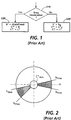
- Such a monochrome mode method is illustrated in Figure 1.
- h s , C* s , L* s , and h d , C* d and L* d denote the hue, chroma, and lightness values of the user selected source and destination colors, respectively.
- the gray to color conversion mode requires the user to specify the L* max , and C* max limits so as to define the source gray pixels.
- the hue angles h min and h max define a hue window with a half width dh.
- An example of a hue window is illustrated in Figure 2. It is noted that h max >h min is the usual case with respect to a hue window. However, if the hue window straddles the zero degree angle, h max will be less than h min .
- the hue angle is defined in the range from 0° to 360°.
- the hue value of the pixel needs to be normalized.
- the chroma of a pixel needs to be checked against an upper bound C* max to insure that the pixel under consideration is gray and is within the specified lightness range. If the pixel in question is a gray pixel, the hue and chroma are changed to that of the selected destination color and the lightness value change would depend upon the choice of gradation.
- the color detection consists of checking if the hue is within the window of the source color. Once the pixel is determined to be within the hue window of the source color, the chroma value of the pixel in question may be checked against a lower limit chroma value C* min to insure that it is not a gray pixel. Once the pixel is determined to be equivalent to a source pixel, the identified pixel has its chroma value set to zero and its hue value becomes undefined.
- the color to color mode requires a slightly different process.
- the color detection consists of checking if the hue is within the window of the source color. Once the pixel is determined to be within the hue window of the source color, the chroma value of the pixel in question may be checked against a lower limit chroma value C* min to insure that it is not a gray pixel. Once the pixel is determined to be equivalent to a source pixel, the gradation mode is checked. If there is no gradation mode, the color to color mode process sets the hue, chroma, and lightness values of the pixel to that of the destination color. For the gradation mode, the conventional device sets the hue value to that of the destination color while maintaining the chroma and lightness values unchanged to provide gradation.
- the establishment of the predetermined values is not dependent upon the saturation (chroma) or lightness (intensity) values of either the source color, the destination color, or the color of the pixel in question because the same predetermined saturation and lightness values are generated for each conversion process, only the hue values change from conversion process to conversion process. After establishing the hue, saturation, and lightness values, the operator adjusts these various values to realize the desired color and gradation.
- step S10 determines whether the incoming pixel value is a gray source. If the pixel value in question is a gray source, step S11 determines whether the pixel value has a chroma value less than the maximum chroma value (C* max ). If the chroma value of the pixel in question is not less than C* max , step S19 establishes the hue, chroma, and lightness values to remain unchanged in the pixel in question.
- C* max maximum chroma value
- step S11 determines that the chroma value of the pixel in question is less than C* max
- step S12 determines whether the lightness value of the pixel in questions is greater than a minimum lightness value (L* min ) and less than a maximum lightness value (L* max ). If this condition is not satisfied at step S12, the hue, chroma, and lightness values are established as described above with respect to step S19.
- step S13 determines whether a gradation mode has been selected. If a gradation mode has been selected, step S20 establishes the hue and chroma values to be the destination hue and chroma values while allowing the lightness value to remain unchanged. On the other hand, if step S13 determines that no gradation mode has been selected, step S14 establishes the hue, chroma, and lightness values to be the destination hue, chroma, and lightness values, respectively.
- step S10 determines that the source is not a gray source
- step S15 determines whether the maximum hue value (h max ) of the hue window is greater than or equal to the minimum hue value (h min ) for the hue window. If h max is greater than h min , step S16 determines whether the hue value of the pixel in question is greater than h min of the hue window and less than h max of the hue window.
- step S15 determines that h max for the hue window is not greater than h min for the hue window
- step S17 determines whether the hue value for the pixel in question is greater than h min for the hue window or less than h max for the hue window. If the hue value of the pixel in question does not meet the condition of step S16 or the condition of step S17, the hue, chroma, and lightness values are established as discussed above with respect to step S19.
- step S18 determines whether the chroma value of the pixel in question is greater than a minimum chroma value (C* min ). If step S18 determines that the chroma value of the pixel in question is not greater than C* min , the hue, chroma, and lightness values remain unchanged as discussed above with respect to step S19. On the other hand, if the chroma value of the pixel in question is greater than C* min , step S21 determines whether the destination color is a gray destination.
- C* min a minimum chroma value
- step S22 determines whether a gradation mode has been selected. If a gradation mode has been selected, step S30 establishes the hue value as being undefined, the chroma value as being equal to zero, and allows the lightness value to remain unchanged. However, if step S22 determines that no gradation has been selected, step S23 establishes the hue value as being undefined, the chroma value as zero, and the lightness value as being equal to the destination lightness value.
- step S24 determines whether a gradation mode has been selected. If no gradation mode has been selected, step S34 establishes the hue value as the destination hue value, the chroma value as the destination chroma value, and the lightness value as the destination lightness value. However, if a gradation has been selected in step S24, step S39 establishes the hue value as the destination hue value, while allowing the chroma value and the lightness value to remain unchanged.
- the system or method must be capable of internally and automatically adjusting the chroma and lightness values of the pixels in question such that the color conversion process can generate converted values which closely resemble the destination color.
- the present invention provides a system for changing a colour corresponding to a source colour to a destination colour, according to claim 1 of the appended claims.
- the present invention further provides a method for changing a colour corresponding to a source colour to a destination colour, according to claim 2 of the appended claims.
- the present invention further provides a system for changing a color corresponding to a source color to a destination color, according to claim 3 of the appended claims.
- the present invention further provides a system for changing a color corresponding to a source color to a destination color, according to claim 4 of the appended claims.
- the present invention further provides a method of electronically generating color destination values to be used in a color conversion process, according to claim 5 of the appended claims.
- the method further comprises the steps of: (g) generating a first set of third destination values corresponding to a source/destination relationship for third source values in a range from the third source value generated in said step (b) to a predetermined minimum third source value using a third function; (h) generating a second set of third destination values corresponding to a source/destination relationship for third source values in a range from the third source value generated in said step (b) to a predetermined maximum third source value using a fourth function; and (i) storing the first and second sets of third destination values in a memory as a look-up table to be used when converting color data corresponding to the selected source color to the selected destination color.
- the present invention further provides a system for changing a color corresponding to a target source color to a destination color, according to claim 6 of the appended claims.
- the system further comprises: third destination value generating means for generating a third destination value using a third function when the third color value is in a range from the third target source value to a predetermined minimum third source value and for generating the third destination value using a fourth function when the third color value is in a range from the third target source value to a predetermined maximum third source value; said output means generating output color data representing the destination color based on the first destination target value and the generated second and third destination values when said comparing means determines that the first color value corresponds to the first target source value.
- said second destination value generating means comprises: first calculating means for generating a first set of second destination values corresponding to a source/destination relationship for second source values in a range from the second source value produced by said converter means to a predetermined minimum second source value using the first function; second calculating means for generating a second set of second destination values corresponding to a source/destination relationship for second source values in a range from the second source value produced by said converter means to a predetermined maximum second source value using the second function; and a first memory to store the first and second sets of second destination values in a look-up table format and to output a value corresponding to the second color value; said output means generating output color data representing the destination color based on the first destination target value and the second destination value outputted by said first memory when said comparing means determines that the first color value corresponds to the first source target value
- said third destination value generating means comprises: third calculating means for generating a third set of third destination values corresponding to a source/destination relationship for
- the present invention further provides a method of changing a color corresponding to a target source color to a destination color, according to claim 7 of the appended claims.
- the method further comprising the steps of: (i) generating a third destination value using a third function when the third color value is in a range from the third target source value to a predetermined minimum third source value; and (j) generating the third destination value using a fourth function when the third color value is in a range from the third target source value to a predetermined maximum third source value; said step (g) generating output color data representing the destination color based on the first target destination value and the generated second and third destination values if said step (d) determines that the first color value corresponds to the first target source value and said step (h) determines that a gradation mode has been selected.
- the present invention further provides a system for converting a color corresponding to a source color to a destination color, according to claim 8 of the appended claims.
- the system further comprises: third destination value table means for pre-storing a plurality of third destination values, each third destination value corresponding to a third source value in a range from a predetermined minimum third source value to a predetermined maximum third source value; said third destination value table means outputting a third destination value that corresponds to an inputted third color value, the inputted third color value being used as the third source value for determining the third destination value when said first comparing means determines that the first color value corresponds to the first target source value and said second comparing means determines that the second color value is within a predetermined range of values; said color data generating means generating output color data representing the destination color based on the first destination target value and the outputted second and third destination values.
- said plurality of second destination values stored in said second destination table means represent first and second functions, the first function corresponding to a source/destination relationship for second source values in a range from a predetermined minimum second source value to a target second source value and the second function corresponding to a source/destination relationship for second source values in a range from the target second source value to a predetermined maximum second source value, the target second source value representing the second source value for the target source color; and said plurality of third destination values stored in said third destination table means represent third and fourth functions, the third function corresponding to a source/destination relationship for third source values in a range from a predetermined minimum third source value to a target third source value and the fourth function corresponding to a source/destination relationship for third source values in a range from the target third source value to a predetermined maximum third source value, the target third source value representing the third source value for the target source color.
- the invention may have the following particular embodiments.
- the second source value is a source lightness value
- the second destination value is a destination lightness value
- the third source value is a source chroma value
- the third destination value is a destination chroma value.
- the first and second functions are a single function forming a line from the predetermined maximum second source value through the second target source value to the predetermined minimum second source value
- the third and fourth functions are a single function forming a line from the predetermined maximum third source value through the third target source value to the predetermined minimum third source value.
- h s , C* s , L* s , and h d , C* d and L* d denote the hue, chroma, and lightness values of the user selected source and destination colors, respectively.
- the gray to color conversion mode requires the user to specify the L* max , and C* max limits so as to define the source gray pixels.
- the hue angles h min and h max , detine a hue window with a half width dh.
- the hue angle is defined in the range from 0° to 360°.
- the hue value of the pixel needs to be normalized.
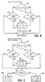
- FIG. 4 illustrates one embodiment of the present invention.
- step S15 determines whether the maximum hue value (h max ) of the hue window is greater than or equal to the minimum hue value (h min ) for the hue window. If h max is greater than h min , step S16 determines whether the hue value of the pixel in question is greater than h min of the hue window and less than h max of the hue window.
- step S17 determines whether the hue value for the pixel in question is greater than h min for the hue window or less than h max for the hue window. If the hue value of the pixel in question does not meet the condition of step S16 or the condition of step S17, the hue, chroma, and lightness values are established at step S19. At step S19, the hue, chroma, and lightness values remain unchanged for the pixel in question. However, if the hue value of the pixel in question meets the conditions of either step S16 or step S17, step S29 establishes the hue, chroma, and lightness values according to the functional relationships which will be discussed in more detail below.
- Figure 5 illustrates another embodiment of the present invention.
- the determination of the hue value is the same as described above with respect to Figure 4.
- Figure 5 modifies Figure 4 with the addition of a gradation branch.
- step S24 determines whether a gradation mode has been selected. If no gradation mode has been selected, step S34 establishes the hue value as the destination hue value, the chroma value as the destination chroma value, and the lightness value as the destination lightness value. However, if a gradation has been selected in step S24, step S29 establishes the hue value, the chroma value, and the lightness value as discussed above with respect to Figure 4.
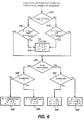
- Figure 6 illustrates a third embodiment of the present invention.
- the method steps having the same labels perform the same functions as described above with respect to Figures 4 and 5.
- Figure 6 modifies Figure 5 with the addition of a gray destination branch.
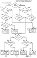
- Figure 7 illustrates a fourth embodiment of the present invention.
- the method steps having the same labels perform the same functions as described above with respect to Figures 4, 5, and 6
- Figure 7 modifies Figure 6 with the addition of a gray source branch.
- step S10 it is determined at step S10 whether the incoming pixel value is a gray source. If the pixel value in question is a gray source, step S11 determines whether the pixel value has a chroma value less than the maximum chroma value (C* max ). If the chroma value of the pixel in question is not less than C* max , step S19 establishes the hue, chroma, and lightness values to remain unchanged in the pixel in question.
- C* max maximum chroma value
- step S11 determines that the chroma value of the pixel in question is less than C* max
- step S12 determines whether the lightness value of the pixel in questions is greater than a minimum lightness value (L* min ) and less than a maximum lightness value (L* max ). If this condition is not satisfied at step S12, the hue, chroma, and lightness values are established as described above with respect to step S19.
- step S13 determines whether a gradation mode has been selected. If a gradation mode has been selected, step S20 establishes the hue and chroma values to be the destination hue and chroma values while allowing the lightness value to remain unchanged. On the other hand, if step S13 determines that no gradation mode has been selected, step S14 establishes the hue, chroma, and lightness values to be the destination hue, chroma, and lightness values, respectively. If step S10 determines that the source is not a gray source, the remaining process begins at step S15.
- Figure 8 illustrates a fifth embodiment of the present invention.
- the method steps having the same labels perform the same functions as described above with respect to Figures 4, 5, 6,and 7 Figure 8 modifies Figure 7 with the addition of a chroma minimum value determination
- step S18 determines whether the chroma value of the pixel in question is greater than a minimum chroma value (C* min ). If step S18 determines that the chroma value of the pixel in question is not greater than C* min , the hue, chroma, and lightness values remain unchanged as discussed above with respect to step S19. On the other hand, if the chroma value of the pixel in question is greater than C* min , step S21 determines whether the destination color is a gray destination. If step S21 determines that the destination color is a gray destination, the remaining process is the same as described with respect to Figure 7 beginning at step S22.
- C* min minimum chroma value
- step S22 determines whether a gradation mode has been selected. If a gradation mode has been selected, step S30 establishes the hue value as being undefined, the chroma value as being equal to zero, and allows the lightness value to remain unchanged However, if step S22 determines that no gradation has been selected, step S23 establishes the hue value as being undefined, the chroma value as zero, and the lightness value as being equal to the destination lightness value.
- step S24 determines whether a gradation mode has been selected. If no gradation mode has been selected, step S34 establishes the hue value as the destination hue value, the chroma value as the destination chroma value, and the lightness value as the destination lightness value. However, if a gradation has been selected in step S24, step S29 establishes the hue value, the chroma value, and the lightness value in the same manner as Figure 4.
- the relationship between the chroma value of the pixel in question and the chroma value for the destination color can be realized in many ways. Also, the relationship between the lightness value of the pixel in question and the lightness value for the destination color can be realized in many ways.
- the relationship between the two chroma values could be a straight line between the points 0 and 255 wherein 0 represents gray and 255 represents the most pure hue color
- the relationship between the two lightness values could also be a straight line between the points 0 and 255 wherein 0 represents black and 255 represents white.
- the chroma and lightness values of the pixel in question are directly mapped to destination chroma and lightness values.
- the chroma and lightness values of the selected source color and the chroma and lightness values of the selected destination color do not affect the respective mapping functions.
- the chroma and lightness values of the pixel in question are not mapped through the chroma and lightness values of the selected source color and the chroma and lightness values of the selected destination color in this embodiment.
- the relationship between the chroma and lightness values of the pixel in question and the destination chroma and lightness values may be mapped through the chroma and lightness values of the selected source color and the chroma and lightness values of the selected destination color.
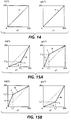
- Such a mapping technique is represented by a "rubber band" transformation as illustrated in Figures 15(A) and 15(B).
- the actual chroma and lightness values for the selected source color and the chroma and lightness values of the designated color are an integral part of the mapping function.
- the actual chroma and lightness values for the selected source color are, initially, mapped directly to the chroma and lightness values of the designated color (point c).
- the mapping function of the "rubber band" transformation will be explained.
- the remaining chroma values, the chroma values other than the chroma values for the selected source and destination color, are mapped utilizing a first straight line (line a) connecting the point representing pure gray to the exact mapped point (c) and a second straight line (line b) connecting the exact mapped point (c) to the point representing a pure hue.
- the chroma values which are less than the chroma value of the selected source color (point c) are mapped according to a first function (line a), and the chroma values greater than the chroma value of the selected source color (point c) are mapped utilizing a second function (line b).
- the chroma values of the selected source and destination colors are integrated into the mapping function such that the mapping function is dependent upon these values, unlike the mapping function of Figure 14.
- This mapping function is also equally applicable to the mapping of the lightness values.
- the mapping takes on the characteristics of a rubber band being originally extended between two points (in case of the chroma mapping, the two points are gray and pure hue) and which has been stretched to a third point (point (c), the point established by the chroma values of the selected source and destination colors) outside the original path of extension (the dotted line or mapping function of Figure 14).
- Figures 15(A) and 15(B) represent only two possibilities for implementing the "rubber band" transformation. More specifically, the apex (point c) of each transformation (function) could be below or above the dotted line (the dotted line representing the direct mapping of Figure 14). Also, the chroma value could be directly mapped as in Figure 14, and the lightness value established as illustrated in Figures 15(A) and 15(B), or the lightness value could be directly mapped as in Figure 14, and the chroma value established as illustrated in Figures 15(A) and 15(B). The type of mapping for the individual values is interchangeable.
- the relationship between the chroma and lightness values of the pixel in question the destination chroma and lightness values may be mapped through the chroma and lightness values of the selected source color and the chroma and lightness values of the selected destination color as follows.
- the chroma and lightness values for the selected source color are mapped directly to the chroma and lightness values of the designated color.
- the remaining chroma and lightness values are mapped utilizing exponential functions or other n-th degree polynomials where n may be greater than two.
- a first exponential function connects the point representing pure gray to the exact mapped point
- a second exponential function connects the exact mapped point to the point representing a pure hue.
- the chroma values which are less than the chroma value of the selected source color are mapped according to a first exponential function or other n-th degree polynomial
- the chroma values greater than the chroma value of the selected source color are mapped utilizing a second exponential function or other n-th degree polynomial.
- the chroma values of the selected source and destination colors are integrated into the mapping function such that the mapping function is dependent upon these values, unlike the mapping function of Figure 14.
- This mapping function is also equally applicable to the mapping of the lightness values. This transformation allows an initial slower approach with a quicker convergence between the two end points and the exact mapped point.
- the relationship between the chroma and lightness values of the pixel in question and the destination chroma and lightness values may also be represented as follows.
- the chroma and lightness values for the selected source color are mapped directly to the chroma and lightness values of the designated color.
- the remaining chroma and lightness values are mapped utilizing exponential functions or other n-th degree polynomials where n is greater than two and a straight line.
- a first exponential function connects the point representing pure gray to the exact mapped point, and a straight line connects the exact mapped point to the point representing a pure hue.
- the chroma values which are less than the chroma value of the selected source color are mapped according to the first exponential function or other n-th degree polynomial, and the chroma values greater than the chroma value of the selected source color are mapped utilizing a straight line.
- the chroma values of the selected source and destination colors are integrated into the mapping function such that the mapping function is dependent upon these values, unlike the mapping function of Figure 14.
- This mapping function is also equally applicable to the mapping of the lightness values. This transformation allows an initial slower approach with a quicker convergence between the gray point and the exact mapped point and a more direct convergence between the exact mapped point and the pure hue point.
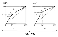
- the relationship between the chroma and lightness values of the pixel in question and the destination chroma and lightness values may be represented as illustrated in Figure 16.
- the chroma and lightness values for the selected source color are mapped directly to the chroma and lightness values of the designated color (point c).
- the remaining chroma and lightness values are mapped utilizing a function which fits the three points (the two end points and the exact mapped point (c)).
- the function as illustrated in Figure 16, is fitted between the point representing pure gray, the exact mapped point (c), and the point representing a pure hue.
- the chroma values of the selected source and destination colors are integrated into the mapping function such that the mapping function is dependent upon these values.
- This mapping function is also equally applicable to the mapping of the lightness values. This transformation allows a more natural or gradual approach between the end points and the exact mapped point (c).
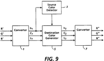
- FIG. 9 illustrates a block diagram showing a basic embodiment of the present invention.
- RGB data from a pixel in question is fed into a first converter 1.
- This first converter converts the RGB data into a color space represented by lightness chroma and hue (L*C*h).
- L*C*h lightness chroma and hue
- the RGB data can also be converted into other color spaces like the Munsell color specification, HSV, HLS, or HSI space without affecting the operations of the present invention.
- the RGB data is converted to the polar form of L*a*b*, L*C*h.
- This destination color generator circuit 5 Upon being converted to the color space format, the values are fed into a destination color generator circuit 5.
- This destination color generator circuit 5 generates destination hue (h2), chroma (C*2), and lightness (L*2) values based upon the hue (h1), chroma (C*1), and lightness (L*1) values inputted thereto and control signals inputted from a source color detector circuit 3.
- the source color detector circuit 3 monitors the hue (h1) and chroma (C*1) values outputted from the first converter 1 to determine what type of destination values are to be generated by the destination color generator circuit 5.
- the destination color generator circuit 5 In accordance with the control signals, the destination color generator circuit 5 generates the proper hue (h2), chroma (C*2), and lightness (L*2) values for the present invention.
- the destination hue (h2), chroma (C*2), and lightness (L*2) values are fed into a second converter 7 which converts the color space back to RGB data which can be further processed to enable a reproduction of the image being inputted into the initial converter 1 with the proper color modifications.
- FIG 10 illustrates a block diagram showing a hardwire circuit for the process illustrated in Figure 4.
- a logic circuit 100 makes an initial determination as whether the hue value of the pixel in question is within a hue window corresponding to the selected source color. To make this determination, the hue value of the pixel in question is fed into the logic circuit as well as the hue maximum value of the hue window and the hue minimum value of the hue window of the selected source color. Using the logic elements as illustrated, the logic circuit 100 will produce a high signal when the hue value of the pixel in question is within the hue window and produce a low signal when the hue value of the pixel in question is outside the hue window.
- the logic circuit 100 includes comparators 10, 12, and 13 which compare the hue window maximum with the hue window minimum, the hue window minimum with the hue value of the pixel, and the hue window maximum with the hue value of the pixel in question, respectfully.
- the AND gates 14, 16 and 17 with the OR gates 15 and 18, along with inverter 11, produce the output signal discussed above from the outputs of the three comparators 10, 12, and 13.
- Multiplexer 19 selects either the hue value of the pixel in question or the hue value of the destination color depending upon the state of the signal inputted from the logic circuit 100. More specifically, multiplexer 19 selects the destination hue value when the logic circuit 100 determines that the hue value of the pixel in question is within the hue window of the selected source color.
- Multiplexer 21 selects either the output of the chroma destination value generator 20 or the chroma value of the pixel in question depending upon the state of the control signal received from the logic circuit 100. More specifically, multiplexer 21 selects the chroma value from the chroma destination value generator 20 when the logic circuit 100 determines that the hue value of the pixel in question is within the hue window of the selected source color.
- the multiplexer 23 selects either the output from the lightness destination value generator 22 or the lightness value of the pixel in question depending upon the state of the control signal outputted from the logic circuit 100. More specifically, the multiplexer 23 selects the output from the lightness destination value generator 22 when the logic circuit 100 determines that the hue value of the pixel in question is within the hue window.
- the chroma destination value generator 20 converts the chroma value of the pixel in question into a destination chroma value utilizing either a look up table or a predetermined set of formulas to establish the relationship between the chroma value of the pixel in question being inputted and the chroma value to be outputted for the designated color.
- the relationship can be stored in a read only memory (ROM) as a look-up table or can be continually generated utilizing a plurality of formulas.
- ROM read only memory
- the plurality of formulas allow flexibility in editing the chroma value being generated for the destination color.
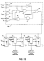
- Figures 11, 12, and 13 illustrate various modifications to Figure 10.
- Figure 11 includes a gradation signal input to the chroma and lightness destination value generators 20 and 22 to enable a greater variety of outputs from these devices. If the gradation signal is off, the chroma and lightness value generators will generate constant values of output corresponding to the chroma and lightness of the destination color.
- Figure 12 includes a gradation signal input and a gray destination signal input to the chroma and lightness destination value generators 20 and 22 to enable a greater variety of outputs from these devices. If the gray destination signal is on, the chroma and lightness value generators will generate a zero chroma value and a lightness destination value dependent upon the gradation requirement as shown in Figure 6.
- Figure 13 includes a gradation signal input and a gray destination signal input to the chroma and lightness destination value generators 20 and 22 and a chroma minimum value detection to enable a greater variety of outputs from these devices.
- mapping functions may incorporate any type of function wherein the selected source chroma and lightness values and the selected destination chroma and lightness values are made an integral part of the functions; i.e., the functions are dependent upon these values.
- the mapping can more sophisticated by having more than one selected source chroma value, selected source lightness value, selected destination chroma value, and selected destination lightness value. For example, the user may select two source and two destination colors of the same hue, thus, producing two selected source/destination chroma values.
- the "rubber band" transformation would consist of three lines with respect to the mapping function. Therefore, the present invention is not limited to the selection of only one source color and one destination color having a same hue.
- the present invention has been described in utilization with respect to digital copiers, the present invention can be utilized in any device which requires the conversion of a color image to another color.
- the mapping of the source chroma and lightness values to the destination chroma and lightness value can be realized utilizing a variety of functions and/or combination of functions to achieve the desired gradation in the final destination product.
Landscapes
- Engineering & Computer Science (AREA)
- Multimedia (AREA)
- Signal Processing (AREA)
- Image Processing (AREA)
- Color Image Communication Systems (AREA)
- Facsimile Image Signal Circuits (AREA)
- Processing Or Creating Images (AREA)
- Editing Of Facsimile Originals (AREA)
Applications Claiming Priority (2)
| Application Number | Priority Date | Filing Date | Title |
|---|---|---|---|
| US93168 | 1993-07-19 | ||
| US08/093,168 US5515172A (en) | 1993-07-19 | 1993-07-19 | Apparatus and method for enhanced color to color conversion |
Publications (3)
| Publication Number | Publication Date |
|---|---|
| EP0635971A2 true EP0635971A2 (de) | 1995-01-25 |
| EP0635971A3 EP0635971A3 (de) | 1995-05-24 |
| EP0635971B1 EP0635971B1 (de) | 1999-10-06 |
Family
ID=22237538
Family Applications (1)
| Application Number | Title | Priority Date | Filing Date |
|---|---|---|---|
| EP94305298A Expired - Lifetime EP0635971B1 (de) | 1993-07-19 | 1994-07-19 | Gerät und Verfahren zur automatischen Farbumwandlung |
Country Status (5)
| Country | Link |
|---|---|
| US (1) | US5515172A (de) |
| EP (1) | EP0635971B1 (de) |
| JP (1) | JP3625074B2 (de) |
| BR (1) | BR9402854A (de) |
| DE (1) | DE69421018T2 (de) |
Cited By (17)
| Publication number | Priority date | Publication date | Assignee | Title |
|---|---|---|---|---|
| DE19501358A1 (de) * | 1995-01-18 | 1996-07-25 | Torsten Dipl Ing Pomierski | Verfahren zur empfindungsgemäßen Farbumstimmung |
| EP0744863A1 (de) * | 1995-05-25 | 1996-11-27 | Mita Industrial Co. Ltd. | Verfahren und Vorrichtung zur Farbkorrektur |
| WO1998056167A1 (en) * | 1997-06-03 | 1998-12-10 | Heidelberger Druckmaschinen Aktiengesellschaft | Color transformation system based on target color image |
| EP1301024A3 (de) * | 2001-10-01 | 2003-06-04 | Canon Kabushiki Kaisha | Bildverarbeitungsverfahren und Gerät, Speichermedium und Programm |
| WO2006029760A3 (de) * | 2004-09-15 | 2006-06-15 | Oce Printing Systems Gmbh | Verfahren und vorrichtung zum umwandeln von quellbilddaten in zielbilddaten |
| EP1966988A4 (de) * | 2005-12-28 | 2009-07-29 | Kwe International Inc | Farbkoordinationssysteme und bildbearbeitung |
| EP1914978A3 (de) * | 2006-10-19 | 2009-08-19 | Murata Machinery Ltd. | Bildverarbeitungsgerät und Bildverarbeitungsverfahren |
| US7589866B2 (en) | 2005-12-28 | 2009-09-15 | Kwe International, Inc. | Editing of digital images, including (but not limited to) color-to-monochromatic conversion and changing the color of a monochromatic image |
| US7639398B2 (en) | 2005-12-28 | 2009-12-29 | Kwe International, Inc. | Color coordinate systems and image editing |
| US7639396B2 (en) | 2005-12-28 | 2009-12-29 | Kwe International, Inc. | Editing of digital images, including (but not limited to) highlighting and shadowing of image areas |
| EP1892949A3 (de) * | 2006-08-21 | 2010-04-21 | Fuji Xerox Co., Ltd. | Bildprozessor, Computerlesbarer Medium zum speichern eines Bildverarbeitungsprogramm und Bildverarbeitungsverfahren |
| US7742206B2 (en) | 2005-02-08 | 2010-06-22 | Sharp Laboratories Of America, Inc. | Methods and systems for color gamut adjustment |
| EP1903773A3 (de) * | 2006-09-20 | 2010-09-22 | Murata Machinery, Ltd. | Bildverarbeitungsgerät und Bildverarbeitungsverfahren |
| US8027070B2 (en) | 2009-02-03 | 2011-09-27 | Sharp Laboratories Of America, Inc. | Methods and systems for hue adjustment |
| US8358441B2 (en) | 2009-04-01 | 2013-01-22 | Sharp Laboratories Of America, Inc. | Methods and systems for sampling and modeling of colorant-limited, multi-colorant color spaces |
| US20230084711A1 (en) * | 2021-06-03 | 2023-03-16 | Baylor University | System and method for displaying super saturated color |
| WO2024145607A1 (en) * | 2022-12-30 | 2024-07-04 | Raven Industries, Inc. | Color angle scanning in crop detection |
Families Citing this family (40)
| Publication number | Priority date | Publication date | Assignee | Title |
|---|---|---|---|---|
| JP3679139B2 (ja) * | 1993-12-29 | 2005-08-03 | 株式会社リコー | カラー画像変換装置 |
| JPH08186727A (ja) * | 1994-12-28 | 1996-07-16 | Canon Inc | 画像処理装置及び方法 |
| JPH08317187A (ja) * | 1995-05-18 | 1996-11-29 | Canon Inc | 画像処理装置及び方法 |
| US6718053B1 (en) * | 1996-11-27 | 2004-04-06 | Chromavision Medical Systems, Inc. | Method and apparatus for automated image analysis of biological specimens |
| DE69627183T2 (de) | 1995-11-30 | 2004-01-29 | Chromavision Med Sys Inc | Verfahren zur automatischen bildanalyse biologischer proben |
| JPH10164380A (ja) * | 1996-10-04 | 1998-06-19 | Canon Inc | 画像処理装置及びその方法 |
| US5982993A (en) * | 1997-11-03 | 1999-11-09 | Xerox Corporation | Method and apparatus for color replacement using an extended ink set |
| US6396505B1 (en) * | 1998-10-07 | 2002-05-28 | Microsoft Corporation | Methods and apparatus for detecting and reducing color errors in images |
| JP3623673B2 (ja) * | 1998-11-24 | 2005-02-23 | 日本電気株式会社 | カラー画像記録装置およびカラー画像記録方法 |
| JP4191832B2 (ja) | 1998-12-22 | 2008-12-03 | 株式会社東芝 | 色変換対応テーブル構築方法および色変換装置 |
| JP3432468B2 (ja) * | 1999-01-27 | 2003-08-04 | 三菱電機株式会社 | 色変換装置および色変換方法 |
| US6404916B1 (en) * | 1999-08-04 | 2002-06-11 | Chromavision Medical Systems, Inc. | Method and apparatus for applying color thresholds in light microscopy |
| US6529291B1 (en) | 1999-09-22 | 2003-03-04 | Xerox Corporation | Fuzzy black color conversion using weighted outputs and matched tables |
| JP4368513B2 (ja) * | 1999-12-27 | 2009-11-18 | 富士フイルム株式会社 | 画像処理方法および装置並びに記録媒体 |
| US6867883B1 (en) | 2000-01-21 | 2005-03-15 | Lexmark International, Inc. | Method and apparatus for expanding a color gamut |
| US6775028B1 (en) | 2000-02-24 | 2004-08-10 | Lexmark International, Inc. | Non-linear method of mapping the lightness and chroma of a display device gamut onto a printing device gamut |
| WO2003042788A2 (en) * | 2001-11-13 | 2003-05-22 | Chromavision Medical Systems, Inc. | A system for tracking biological samples |
| US6934411B2 (en) * | 2002-01-29 | 2005-08-23 | Kwe International, Inc. | Method and apparatus for RGB color conversion that can be used in conjunction with lossless and lossy image compression |
| US20050037406A1 (en) * | 2002-06-12 | 2005-02-17 | De La Torre-Bueno Jose | Methods and apparatus for analysis of a biological specimen |
| US7272252B2 (en) * | 2002-06-12 | 2007-09-18 | Clarient, Inc. | Automated system for combining bright field and fluorescent microscopy |
| US7113649B2 (en) * | 2002-06-24 | 2006-09-26 | Eastman Kodak Company | Enhancing the tonal characteristics of digital images |
| US20040202357A1 (en) | 2003-04-11 | 2004-10-14 | Perz Cynthia B. | Silhouette image acquisition |
| EP1517542B1 (de) * | 2003-09-01 | 2010-11-10 | Samsung Electronics Co., Ltd. | Verfahren und Apparat zur Anpassung von Farben in Bildern |
| JP4141923B2 (ja) * | 2003-09-18 | 2008-08-27 | 村田機械株式会社 | カラー画像処理装置 |
| US7653260B2 (en) * | 2004-06-17 | 2010-01-26 | Carl Zeis MicroImaging GmbH | System and method of registering field of view |
| US8582924B2 (en) * | 2004-06-30 | 2013-11-12 | Carl Zeiss Microimaging Gmbh | Data structure of an image storage and retrieval system |
| JP4513961B2 (ja) * | 2004-11-05 | 2010-07-28 | 富士ゼロックス株式会社 | 色調整方法および色調整装置 |
| US20070031043A1 (en) * | 2005-08-02 | 2007-02-08 | Perz Cynthia B | System for and method of intelligently directed segmentation analysis for automated microscope systems |
| US20070091109A1 (en) * | 2005-09-13 | 2007-04-26 | Roscoe Atkinson | Image quality |
| JP4915071B2 (ja) * | 2005-09-22 | 2012-04-11 | 株式会社ニコン | 顕微鏡、およびバーチャルスライド作成システム |
| US7486418B2 (en) * | 2005-12-28 | 2009-02-03 | Kwe International, Inc. | Editing (including contrast and sharpness editing) of digital images |
| US7489420B2 (en) * | 2005-12-28 | 2009-02-10 | Kwe International, Inc. | Color editing (including brightness editing) using color coordinate systems including systems with a coordinate defined by a square root of a quadratic polynomial in tristimulus values and, possibly, by a sign of a function of one or more of tristimulus values |
| US7495800B2 (en) * | 2005-12-28 | 2009-02-24 | Kwe International, Inc. | Color coordinate systems including systems with a coordinate defined by a square root of a quadratic polynomial in tristimulus values and, possibly, by a sign of a function of one or more of tristimulus values |
| JP2007208736A (ja) * | 2006-02-02 | 2007-08-16 | Canon Inc | 色処理方法および装置 |
| JP4931219B2 (ja) * | 2007-03-02 | 2012-05-16 | キヤノン株式会社 | 情報処理装置及び情報処理方法 |
| US7995242B2 (en) | 2007-05-31 | 2011-08-09 | Sharp Laboratories Of America, Inc. | Systems and methods for attenuation of near-neutral image colors |
| WO2009106081A1 (en) | 2008-02-29 | 2009-09-03 | Dako Denmark A/S | Systems and methods for tracking and providing workflow information |
| EP3110128A1 (de) * | 2015-06-25 | 2016-12-28 | Thomson Licensing | Farbtonbereichsumsetzung basierend auf der abbildung von durch vereinfachte cusplinien gewonnenen spitzenfarben |
| US11423854B2 (en) * | 2019-04-08 | 2022-08-23 | Chongqing Hkc Optoelectronics Technology Co., Ltd. | Driving method and system of display panel, and display device |
| CN112114929B (zh) * | 2020-09-29 | 2023-11-17 | 青岛海信移动通信技术有限公司 | 显示设备及其图像显示方法 |
Family Cites Families (6)
| Publication number | Priority date | Publication date | Assignee | Title |
|---|---|---|---|---|
| US4500919A (en) * | 1982-05-04 | 1985-02-19 | Massachusetts Institute Of Technology | Color reproduction system |
| US4972257A (en) * | 1989-04-03 | 1990-11-20 | Xerox Corporation | Operator adjustable color image processing |
| GB9002477D0 (en) * | 1990-02-05 | 1990-04-04 | Crosfield Electronics Ltd | Improvements relating to control data arrays |
| US5202935A (en) * | 1990-10-19 | 1993-04-13 | Matsushita Electric Industrial Co., Ltd. | Color conversion apparatus for altering color values within selected regions of a reproduced picture |
| JPH07101916B2 (ja) * | 1991-05-14 | 1995-11-01 | 富士ゼロックス株式会社 | カラー画像編集装置 |
| JPH04336870A (ja) * | 1991-05-14 | 1992-11-25 | Fuji Xerox Co Ltd | カラー画像記録装置 |
-
1993
- 1993-07-19 US US08/093,168 patent/US5515172A/en not_active Expired - Lifetime
-
1994
- 1994-07-11 JP JP15850894A patent/JP3625074B2/ja not_active Expired - Fee Related
- 1994-07-19 EP EP94305298A patent/EP0635971B1/de not_active Expired - Lifetime
- 1994-07-19 DE DE69421018T patent/DE69421018T2/de not_active Expired - Fee Related
- 1994-07-20 BR BR9402854A patent/BR9402854A/pt not_active IP Right Cessation
Cited By (27)
| Publication number | Priority date | Publication date | Assignee | Title |
|---|---|---|---|---|
| DE19501358A1 (de) * | 1995-01-18 | 1996-07-25 | Torsten Dipl Ing Pomierski | Verfahren zur empfindungsgemäßen Farbumstimmung |
| EP0744863A1 (de) * | 1995-05-25 | 1996-11-27 | Mita Industrial Co. Ltd. | Verfahren und Vorrichtung zur Farbkorrektur |
| US5790261A (en) * | 1995-05-25 | 1998-08-04 | Mita Industrial Co., Ltd. | Color correction device to correct errors in input and output portions of an image developing device and method thereof |
| WO1998056167A1 (en) * | 1997-06-03 | 1998-12-10 | Heidelberger Druckmaschinen Aktiengesellschaft | Color transformation system based on target color image |
| KR100533310B1 (ko) * | 2001-10-01 | 2005-12-05 | 캐논 가부시끼가이샤 | 화상 처리 방법 및 장치, 및 기억 매체 |
| US6814420B2 (en) | 2001-10-01 | 2004-11-09 | Canon Kabushiki Kaisha | Image processing method and apparatus, storage medium and program |
| US7684063B2 (en) | 2001-10-01 | 2010-03-23 | Canon Kabushiki Kaisha | Image processing method and apparatus, storage medium and program for achieving concordance between print colors and display colors |
| AU2002301275B2 (en) * | 2001-10-01 | 2008-02-14 | Canon Kabushiki Kaisha | Image Processing Method and Apparatus, Storage Medium and Program |
| CN101119432B (zh) * | 2001-10-01 | 2013-06-05 | 佳能株式会社 | 图像处理方法和图像处理装置 |
| EP1301024A3 (de) * | 2001-10-01 | 2003-06-04 | Canon Kabushiki Kaisha | Bildverarbeitungsverfahren und Gerät, Speichermedium und Programm |
| WO2006029760A3 (de) * | 2004-09-15 | 2006-06-15 | Oce Printing Systems Gmbh | Verfahren und vorrichtung zum umwandeln von quellbilddaten in zielbilddaten |
| CN101019412B (zh) * | 2004-09-15 | 2010-07-07 | Oce印刷系统有限公司 | 用于将源图像数据转换为目标图像数据的方法和装置 |
| US7742206B2 (en) | 2005-02-08 | 2010-06-22 | Sharp Laboratories Of America, Inc. | Methods and systems for color gamut adjustment |
| US7639398B2 (en) | 2005-12-28 | 2009-12-29 | Kwe International, Inc. | Color coordinate systems and image editing |
| US7639396B2 (en) | 2005-12-28 | 2009-12-29 | Kwe International, Inc. | Editing of digital images, including (but not limited to) highlighting and shadowing of image areas |
| EP1966988A4 (de) * | 2005-12-28 | 2009-07-29 | Kwe International Inc | Farbkoordinationssysteme und bildbearbeitung |
| US7589866B2 (en) | 2005-12-28 | 2009-09-15 | Kwe International, Inc. | Editing of digital images, including (but not limited to) color-to-monochromatic conversion and changing the color of a monochromatic image |
| US8031965B2 (en) | 2006-08-21 | 2011-10-04 | Fuji Xerox Co., Ltd. | Image processor, computer readable medium storing image processing program, and image processing method |
| CN101132472B (zh) * | 2006-08-21 | 2013-02-13 | 富士施乐株式会社 | 图像处理器以及图像处理方法 |
| EP1892949A3 (de) * | 2006-08-21 | 2010-04-21 | Fuji Xerox Co., Ltd. | Bildprozessor, Computerlesbarer Medium zum speichern eines Bildverarbeitungsprogramm und Bildverarbeitungsverfahren |
| EP1903773A3 (de) * | 2006-09-20 | 2010-09-22 | Murata Machinery, Ltd. | Bildverarbeitungsgerät und Bildverarbeitungsverfahren |
| EP1914978A3 (de) * | 2006-10-19 | 2009-08-19 | Murata Machinery Ltd. | Bildverarbeitungsgerät und Bildverarbeitungsverfahren |
| US8027070B2 (en) | 2009-02-03 | 2011-09-27 | Sharp Laboratories Of America, Inc. | Methods and systems for hue adjustment |
| US8358441B2 (en) | 2009-04-01 | 2013-01-22 | Sharp Laboratories Of America, Inc. | Methods and systems for sampling and modeling of colorant-limited, multi-colorant color spaces |
| US20230084711A1 (en) * | 2021-06-03 | 2023-03-16 | Baylor University | System and method for displaying super saturated color |
| US11816819B2 (en) * | 2021-06-03 | 2023-11-14 | Baylor University | System and method for displaying super saturated color |
| WO2024145607A1 (en) * | 2022-12-30 | 2024-07-04 | Raven Industries, Inc. | Color angle scanning in crop detection |
Also Published As
| Publication number | Publication date |
|---|---|
| EP0635971A3 (de) | 1995-05-24 |
| DE69421018D1 (de) | 1999-11-11 |
| US5515172A (en) | 1996-05-07 |
| JP3625074B2 (ja) | 2005-03-02 |
| JPH0774933A (ja) | 1995-03-17 |
| EP0635971B1 (de) | 1999-10-06 |
| BR9402854A (pt) | 1995-04-04 |
| DE69421018T2 (de) | 2000-04-13 |
Similar Documents
| Publication | Publication Date | Title |
|---|---|---|
| US5515172A (en) | Apparatus and method for enhanced color to color conversion | |
| US5768403A (en) | Image-area identifying system for a color image processing apparatus | |
| US5166810A (en) | Image quality control system for an image processing system | |
| JP3256982B2 (ja) | 画像処理装置 | |
| US5414538A (en) | Image-dependent exposure enhancement | |
| JP3384580B2 (ja) | 地肌除去方法 | |
| JP3003261B2 (ja) | カラー画像認識装置 | |
| JP2990306B2 (ja) | カラー画像記録装置のマーカドット検出方式 | |
| US6342951B1 (en) | Gamut mapping algorithm using inverted gamma function | |
| US5436733A (en) | Image processing apparatus for combining image data and texture image data | |
| US20010035989A1 (en) | Method, apparatus and recording medium for color correction | |
| JPH07101916B2 (ja) | カラー画像編集装置 | |
| JP2600515B2 (ja) | 画像処理方法 | |
| US20080018920A1 (en) | Image processing apparatus | |
| EP0070680A1 (de) | Farbbildreproduktion | |
| US5200832A (en) | Color image recording device with color edit and conversion processing | |
| JP2998278B2 (ja) | カラー画像記録装置におけるモノカラー編集方法及び装置 | |
| US7466453B2 (en) | Image processing apparatus | |
| US5481372A (en) | Area control system for image processing apparatus | |
| US6781715B1 (en) | Image processing method and system | |
| JP2000184222A (ja) | カラー画像信号処理装置およびカラー画像信号処理方法 | |
| JPH04336868A (ja) | 画像処理装置 | |
| JP2890456B2 (ja) | 画像処理装置 | |
| JPH0440072A (ja) | 画像処理装置 | |
| JP3352106B2 (ja) | 画像処理装置及び方法 |
Legal Events
| Date | Code | Title | Description |
|---|---|---|---|
| PUAI | Public reference made under article 153(3) epc to a published international application that has entered the european phase |
Free format text: ORIGINAL CODE: 0009012 |
|
| AK | Designated contracting states |
Kind code of ref document: A2 Designated state(s): DE FR GB |
|
| PUAL | Search report despatched |
Free format text: ORIGINAL CODE: 0009013 |
|
| AK | Designated contracting states |
Kind code of ref document: A3 Designated state(s): DE FR GB |
|
| 17P | Request for examination filed |
Effective date: 19951124 |
|
| 17Q | First examination report despatched |
Effective date: 19980305 |
|
| GRAG | Despatch of communication of intention to grant |
Free format text: ORIGINAL CODE: EPIDOS AGRA |
|
| GRAG | Despatch of communication of intention to grant |
Free format text: ORIGINAL CODE: EPIDOS AGRA |
|
| GRAH | Despatch of communication of intention to grant a patent |
Free format text: ORIGINAL CODE: EPIDOS IGRA |
|
| GRAH | Despatch of communication of intention to grant a patent |
Free format text: ORIGINAL CODE: EPIDOS IGRA |
|
| GRAA | (expected) grant |
Free format text: ORIGINAL CODE: 0009210 |
|
| AK | Designated contracting states |
Kind code of ref document: B1 Designated state(s): DE FR GB |
|
| REF | Corresponds to: |
Ref document number: 69421018 Country of ref document: DE Date of ref document: 19991111 |
|
| ET | Fr: translation filed | ||
| PLBE | No opposition filed within time limit |
Free format text: ORIGINAL CODE: 0009261 |
|
| STAA | Information on the status of an ep patent application or granted ep patent |
Free format text: STATUS: NO OPPOSITION FILED WITHIN TIME LIMIT |
|
| 26N | No opposition filed | ||
| REG | Reference to a national code |
Ref country code: GB Ref legal event code: IF02 |
|
| REG | Reference to a national code |
Ref country code: GB Ref legal event code: 746 Effective date: 20050512 |
|
| PGFP | Annual fee paid to national office [announced via postgrant information from national office to epo] |
Ref country code: DE Payment date: 20070712 Year of fee payment: 14 |
|
| PGFP | Annual fee paid to national office [announced via postgrant information from national office to epo] |
Ref country code: GB Payment date: 20070718 Year of fee payment: 14 |
|
| PGFP | Annual fee paid to national office [announced via postgrant information from national office to epo] |
Ref country code: FR Payment date: 20070710 Year of fee payment: 14 |
|
| GBPC | Gb: european patent ceased through non-payment of renewal fee |
Effective date: 20080719 |
|
| PG25 | Lapsed in a contracting state [announced via postgrant information from national office to epo] |
Ref country code: DE Free format text: LAPSE BECAUSE OF NON-PAYMENT OF DUE FEES Effective date: 20090203 |
|
| REG | Reference to a national code |
Ref country code: FR Ref legal event code: ST Effective date: 20090331 |
|
| PG25 | Lapsed in a contracting state [announced via postgrant information from national office to epo] |
Ref country code: GB Free format text: LAPSE BECAUSE OF NON-PAYMENT OF DUE FEES Effective date: 20080719 |
|
| PG25 | Lapsed in a contracting state [announced via postgrant information from national office to epo] |
Ref country code: FR Free format text: LAPSE BECAUSE OF NON-PAYMENT OF DUE FEES Effective date: 20080731 |