EP0636308B1 - Mécanisme d'amenée pour des presse-balles - Google Patents
Mécanisme d'amenée pour des presse-balles Download PDFInfo
- Publication number
- EP0636308B1 EP0636308B1 EP93202182A EP93202182A EP0636308B1 EP 0636308 B1 EP0636308 B1 EP 0636308B1 EP 93202182 A EP93202182 A EP 93202182A EP 93202182 A EP93202182 A EP 93202182A EP 0636308 B1 EP0636308 B1 EP 0636308B1
- Authority
- EP
- European Patent Office
- Prior art keywords
- fulcrum
- agricultural baler
- baler according
- duct
- path
- Prior art date
- Legal status (The legal status is an assumption and is not a legal conclusion. Google has not performed a legal analysis and makes no representation as to the accuracy of the status listed.)
- Expired - Lifetime
Links
- 239000000463 material Substances 0.000 claims description 42
- 238000000034 method Methods 0.000 claims description 10
- 125000004122 cyclic group Chemical group 0.000 claims description 4
- 230000006835 compression Effects 0.000 claims description 2
- 238000007906 compression Methods 0.000 claims description 2
- 239000004460 silage Substances 0.000 description 8
- 230000000712 assembly Effects 0.000 description 6
- 238000000429 assembly Methods 0.000 description 6
- 230000007423 decrease Effects 0.000 description 6
- 239000004463 hay Substances 0.000 description 5
- 239000010902 straw Substances 0.000 description 5
- 230000000694 effects Effects 0.000 description 2
- 244000025254 Cannabis sativa Species 0.000 description 1
- 230000015572 biosynthetic process Effects 0.000 description 1
- 230000003247 decreasing effect Effects 0.000 description 1
- 238000010586 diagram Methods 0.000 description 1
- 238000012986 modification Methods 0.000 description 1
- 230000004048 modification Effects 0.000 description 1
- 239000007787 solid Substances 0.000 description 1
- 238000010408 sweeping Methods 0.000 description 1
- 230000001960 triggered effect Effects 0.000 description 1
Images


Classifications
-
- A—HUMAN NECESSITIES
- A01—AGRICULTURE; FORESTRY; ANIMAL HUSBANDRY; HUNTING; TRAPPING; FISHING
- A01D—HARVESTING; MOWING
- A01D90/00—Vehicles for carrying harvested crops with means for selfloading or unloading
- A01D90/02—Loading means
-
- A—HUMAN NECESSITIES
- A01—AGRICULTURE; FORESTRY; ANIMAL HUSBANDRY; HUNTING; TRAPPING; FISHING
- A01F—PROCESSING OF HARVESTED PRODUCE; HAY OR STRAW PRESSES; DEVICES FOR STORING AGRICULTURAL OR HORTICULTURAL PRODUCE
- A01F15/00—Baling presses for straw, hay or the like
- A01F15/08—Details
- A01F15/10—Feeding devices for the crop material e.g. precompression devices
- A01F15/101—Feeding at right angles to the compression stroke
-
- A—HUMAN NECESSITIES
- A01—AGRICULTURE; FORESTRY; ANIMAL HUSBANDRY; HUNTING; TRAPPING; FISHING
- A01F—PROCESSING OF HARVESTED PRODUCE; HAY OR STRAW PRESSES; DEVICES FOR STORING AGRICULTURAL OR HORTICULTURAL PRODUCE
- A01F15/00—Baling presses for straw, hay or the like
- A01F15/08—Details
- A01F15/10—Feeding devices for the crop material e.g. precompression devices
- A01F15/101—Feeding at right angles to the compression stroke
- A01F2015/102—Feeding at right angles to the compression stroke the pressing chamber is fed from the bottom side
-
- Y—GENERAL TAGGING OF NEW TECHNOLOGICAL DEVELOPMENTS; GENERAL TAGGING OF CROSS-SECTIONAL TECHNOLOGIES SPANNING OVER SEVERAL SECTIONS OF THE IPC; TECHNICAL SUBJECTS COVERED BY FORMER USPC CROSS-REFERENCE ART COLLECTIONS [XRACs] AND DIGESTS
- Y10—TECHNICAL SUBJECTS COVERED BY FORMER USPC
- Y10S—TECHNICAL SUBJECTS COVERED BY FORMER USPC CROSS-REFERENCE ART COLLECTIONS [XRACs] AND DIGESTS
- Y10S56/00—Harvesters
- Y10S56/01—Crusher
Definitions
- the present invention relates to agricultural balers for the formation of bales of crop material, such as hay, straw or silage in a bale chamber, and more particularly to the loading means for the transportation of said material from within a duct to the bale chamber.
- hay, straw, silage or similar crop material that has been previously cut, windrowed or swathed is picked up from the ground by a pick-up unit, fed into a duct by a packer unit and loaded in successive batches or charges into an elongated bale chamber by tines of a stuffer unit in timed sequence with a reciprocating plunger.
- the plunger compresses the material into bales and, at the same time, gradually advances the bales towards the outlet of the bale chamber.
- a knotter device is actuated which wraps cord, twine or other flexible binding material around the bale and secures the ends of the binding material together.
- the packer unit precompresses the crop material in the duct against a backstop formed by the plunger, when closing off the entrance of the bale chamber.
- the stuffer unit is designed to quickly load charges of said crop material into the bale chamber within the short interval during which the reciprocating plunger clears the entrance of the bale chamber.
- this is accomplished by a fork assembly whereof the arms are rotatably connected to cranks, said arms being provided with longitudinally extending slots in which stationary journals are received. A uniform revolution of the cranks makes the arms shift along and pivot about the journals so that the tines of the fork travel along a generally kidney-shaped path with a varying speed.
- the maximum or peak speed is obtained when the distance between the connection to the cranks and the stationary journals reaches its minimum, since the arms then act as levers with very close fulcrum points.
- Such system permits a quick sweep of the material behind the packer unit through the duct and to the entrance of the bale chamber.
- This type of stuffer unit was originally designed for the baling of dry, low density material such as straw or hay, but meanwhile there has been an important shift in agriculture from the use of hay to the use of silage. Silage grass can also be baled, but since it has a higher humidity and a higher density than the other crop materials, the load on the components of the stuffer unit increases accordingly.
- a stuffer overload protection which has been developed for the baling of straw or hay, will easily be triggered by the normal forces which occur during the baling of silage.
- a conventional protection is the use of a shear bolt assembly in the drive line of the stuffer unit. When the loads exceed the shear force of the bolt, the stuffer is disconnected before its components are damaged, but it will cost the operator valuable time to render the baler operable again, also because it may be required to clear the duct manually before the baler can be restarted.
- a part of the forces which occur during the baling of silage, can be reduced by applying a low-friction layer to the inner surfaces of the duct, as described in FR-B-2.617.673.
- This layer will diminish the friction forces of the silage in the duct, but does not cope with the effect of its heavier mass: the larger inertia forces on the tines of the stuffer unit thus remain unchanged.
- the baler still is vulnerable to triggering of the overload protection by the normal silage forces.
- an agricultural baler which comprises:
- the baler is characterized in that it further comprises means enabling movement of said fulcrum relative to said drive shaft between a first and a second position.
- the guide means preferably comprises a journal which is mounted coaxially with said fulcrum and which fits closely between the longitudinal sides of an oblong slot, provided in the fork lever.
- the fulcrum is fixed to a pivot member, which is movable by the fork lever or by a cam member of the crank arm. The speed course of the tines can be changed by removing a plug from the fork lever in order to increase the length of the slot and by securing the pivot member relative to the drive shaft.
- a method for reducing peak velocities of a loading means of an agricultural baler said baler having:
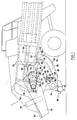
- a baler 1 having a fore-and-aft extending bale case 10 with a rectangular cross section defining a baling chamber.
- the bale case 10 is supported in an upwardly and forwardly inclined manner by struts 14 having ground-engaging wheels 16 at their lowermost ends.
- a downwardly and forwardly projecting tongue 18 at the front of the bale case 10 is adapted for hitching the baler 1 to a towing vehicle (not shown) for advancing the same across a field.
- An enclosed plunger 20 reciprocates fore-and-aft within the baling chamber for periodically compacting material presented to the chamber through an inlet 22 in the floor 24 of bale case 10 across the full width thereof.
- An upwardly curving loading duct 26 depends from the bale case 10 and has its upper discharge end 28 in registration with the inlet 22, while the lower receiving end 30 of the duct 26 is remote from inlet 22 and is disposed substantially forwardly thereof.
- the duct 26 has a curved top wall 32 which is provided with laterally spaced, longitudinal slots (not shown) extending the full length thereof, and a solid curved bottom wall 36.
- the lower end 30 of the duct is positioned directly behind a crop pick-up 40 which may be of any design capable of picking up windrowed or swathed crop material from the field and delivering the same rearwardly into the end 30 of the duct 26.
- the pick-up 40 has a series of lifting tines 42 which sweep the crop upwardly to stub augers 44 which gather the crop centrally and deliver it rearwardly into the lower end 30 of the duct 26.
- a packer unit 48 is positioned directly behind the crop pick-up 40 and above the duct end 30 for making a pre-compressed charge of material within the duct 26 preparatory to loading the bale case 10. It contains a plurality of forks with tines 50 which are moved along a generally kidney-shaped path (not shown) to thereby project into the crop material in the lower end 30, push charges thereof rearwardly and upwardly in the duct 26 and retract therefrom while returning to their foremost position.
- a power input shaft 52 along the tongue 18 carries a flywheel 54 at the upper end of said tongue 18, immediately adjacent a right angle gearbox 56 coupled with the input shaft 52.
- the gearbox 56 drives a pair of crank arms 58 which are rotatably linked to a pair of pitman arms 60 of the plunger 20.
- the gearbox 56 rotates the crank arms 58 to thereby reciprocate the plunger 20 within the bale case 10.
- the same gearbox 56 drives a shaft 86 of a sprocket 84.
- Other output shafts (not shown) of the gearbox 56 provide either directly or indirectly driving power to the packer unit 48, the pick-up 40 and the stub augers 44.
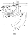
- a stuffing fork 66 for periodically sweeping an accumulated charge of crop material from the duct 26 into the bale case 10.
- the fork 66 has a transverse square tube 68 spanning the duct 26 above the latter, to which tube 68 a series of laterally spaced-apart, elongated tines 70 is attached.
- the tines 70 are spaced apart in accordance with the slots in the top wall 32 of duct 26, such that during the loading cycle the tines 70 may enter the duct 26 through said slots and move along the bottom wall 36 toward the inlet 22 of the bale case 10.
- the fork 66 also includes a pair of levers 72 at opposite ends of the tube 68, which levers 72 carry the square tube 68 at their rearmost end and are rotatably coupled at their foremost end with a pair of cranks 74 through pivots 76.
- the cranks 74 are rigidly affixed to opposite ends of a shaft 78 that spans the bale case 10 above the packer unit 48.
- the crank 74 on the left side of the baler 1 is also rigidly connected by a shear bolt (not shown) to a large sprocket 80, which receives driving power from an endless chain 82 entrained around the drive sprocket 84, carried by the drive shaft 86. In this manner the foremost or operated end of each lever 72 is mounted for movement in a circular path of travel about the axis of shaft 78.
- the rearward ends of the levers 72 are operably supported by guide means, comprising a pair of journals 88, which serve as lever fulcrums, and longitudinally extending slots 90 in said pair of levers 72, in which the journals 88 are received.
- the journals 88 fit closely within the sides of the slots 90 as to make the fulcrums follow a predetermined path 91 (shown in dashed lines in Figure 2) relative to the levers 72.
- the journals 88 are rotatably mounted to two generally triangular pivot members 94, which are pivotably attached to the left and right side of the bale case 10 through a pair of pivots 96, positioned behind and slightly above the crank drive shaft 78.
- the journals 88 and pivot members 94 are forced upwardly by springs 99, of which the one end is attached to the upper half of the members 94 and the other end to the bale case 10. They are held in a first position as shown in full lines in Figure 2 by a pair of stop bolt assemblies 98, comprising supports, which are affixed to the bale case 10, and stop bolts, interacting with abutments 100 attached to and extending from the lower edge of the pivot members 94.
- the bolts and nuts of said assemblies 98 are adjustable to modify this first, upmost position of said journals 88.
- the front portion of the longitudinally extending slots 90 is filled with plugs 106, the function whereof will be explained further when the operation of the loading means is considered.
- the plugs are secured to the levers 72 by a rim fitting over said front portion of the slots 90 and by bolt means (not shown).
- cranks 74 Opposite to the lever pivots 76 the cranks 74 comprise arms, incorporating cam members 102, which have substantially straight and substantially circular portions, the latter being coaxial with the drive shaft 78.
- cranks 74 When said cranks 74 are rotated clock-wise as viewed by a person looking at the left of the baler, first the straight portions of the cam members 102 come into contact with rollers 104, which are rotatably connected to the pivot members 94, and push said members 94 upwardly, whereafter the circular portions keep the rollers 104 and the members 94 in a stationary position, for a purpose which will be explained further on.
- the bolt assemblies 98 are adjusted to almost engage the abutments 100 during the run of the rollers 104 over the circular portion of the cam members 102.
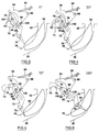
- FIG 3 shows the loading means in an initial configuration, in which the tines 70 are arranged outside the duct 26.
- the cranks 74 are rotated slightly over their upmost position, thereby determining the position of the lever pivots 76.
- the fork tines 70 are retracted from the duct, so that no significant load is applied to the levers 72 and hence to the journals 88.
- the springs 99 hold the stop members 100 of the pivot members 94 against the bolt assemblies 98.
- the pivots 76 and the journals 88 univocally position the levers 72 and the tines 70.
- Figure 7 shows the configuration of the loading means after rotation of the cranks 74 over another 35°.
- the tines 76 now have swept through more than half of the duct 26, thereby pushing the crop material through the inlet 22 of the bale case 10.
- the load of the crop material on the tines on the one hand and the action of the pivots 76 on the other hand tend to keep the journals 88 down and stuck to their second position.
- the pivot members 94 are held down by the forces on the journals 88 since the tension forces of the springs 99 compensate only a portion thereof, thus leaving the members 94 and the journals 88 in their second, lowermost position.
- the pivots 76 would pull the tines 70 out of the duct 26 before they had reached the inlet 22 of the bale case 10, thus feeding only an incomplete charge of crop material to the bale case 10.
- the substantially straight portions of the cam members 102 have been designed to push the pivot members 94 upwardly during the further rotation of the cranks 74 and the progression of the tines 70 in the duct 26. While the rollers 104 of the members 94 contact said straight portions, the journals 88 remain practically in abutment with the plugs 106 in the slots 90 of the levers 72. As the fulcrum of the levers 72 raises accordingly, the tines 70 are lifted up to the top of the duct 26 to thereby stuff a full charge of crop material into the bale case 10.
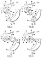
- Figures 9 and 10 illustrate the further progression of the tines 70 along the path 92 outside the duct 26.
- the tines 70 are not loaded anymore and the mere action of the springs 99 is capable of keeping the pivot members 94 in their first position.
- the levers 72 travel over the stationary journals 88, while their pivots 76 are rotated by the cranks 74.
- the length of the one lever arm defined by the pivots 76 and the journals 88 increases, while the opposite lever arm between the top of the tines 70 and the same journals 88 decreases. Accordingly, the ratio of the speed of the tines 70 to the (constant) speed of the pivots 76 is reduced. This speed decrease is clearly shown in the final portion of the graph 110 of the speed course in Figure 15.
- Figures 3 to 10 when considered together with Figure 15, reveal that the tines 70 move slowly along the forward and downward portion of the path 92, when no crop material is fed to the bale case 10, but sweep at a much higher speed through the duct 26, along the rearward and upward portion of the path 92, when a charge of crop material has to be pushed up the bale case 10.
- the speed course of prior art configurations which is represented by a full-lined graph 112 in Figure 15, contains a portion wherein the speed of the tines 70 raises quickly to a high level, whereafter it decreases at the same rate, while the speed course of the loading means of the invention stabilizes at a significantly lower level, before returning to the initial low speed.
- the maximum forces on the loading means which are caused by the inertia and friction of the crop material in the duct 26 and which are proportional to the speed of the tines 70.
- the maximum speed of the tines 70 is determined by the leverage about the journals 88, in which the minimum distance between the constantly rotated pivots 76 and the journals 88 is crucial. This distance can be modified by replacing the plug 106 by a longer or shorter plug, to thereby limit or extend the path 91 along which the fulcrum can travel relative to the levers 72. A longer plug will stop the journals 88 at a larger distance from the pivots 76 and provide a longer lever arm inbetween. As there remains a shorter lever arm between the journals 88 and the top of the tines 70, these will be pivoted at a slower speed about the journals 88. When a shorter plug is used the opposite effect is obtained and the tines 70 will be pivoted at a higher speed, when compared to the first configuration of the invention.
- the use of a loading means according to the prior art configuration, as described in US-A-4.106.267, may prove more effective to obtain a good, even loading of the crop material in the bale case 10.
- Such can be the case when dry, light straw is being baled.
- the baler 1 of the present invention is easily adaptable to such configuration.
- the operative length of the slots 90 is increased by removing the plugs 106 from the levers 72. It suffices to unscrew the bolt means by which said plugs 106 are secured to the levers 72 and slide them out of the slots 90.
- the cleared portions of the slots 90 are equally dimensioned to receive the journals 88 therein and to make the fulcrums of the levers 72 follow an extended, predetermined path 91 relative to said levers 72.
- the pivot members 94 are secured to the bale case 10 by bolting the stop members 100 to the supports of the stop bolt assemblies 98, whereby the journals 88 get fixed relative to the crank drive shaft 78.
- the movement of the tines 70 starts to deviate from that of the previous configuration, when the cranks 70 have been rotated over 70°.
- the journals 88 enter the portions of the slots 90 which were previously blocked by the plugs 106 (now shown in phantom).
- the pivot members 94 are not forced down anymore and the distance between the pivots 76 and the journals 88 further decreases.
- the top of the tines 70 is moved rearwardly along a slightly modified path 108 which is represented by a full line in Figures 11 to 14.
- the tines 70 reach their upmost position when the cranks 74 are rotated over 170°.
- the journals 88 have left the portions of the slots 90, which were previously occupied by the plugs 106.
- the location of all components is now fully comparable to their location in Figure 8: the journals 88 are travelling in the rear portion of slots 90 and the pivot members 94 are held in their upmost position.
- the tines 70 travel along the upper portion of the path 92 and the speed course also returns to that of the previous configuration, as illustrated in Figure 15.
- the loading means can resume their initial way of operation, whereby the peak speed of the tines 70 is flattened out and the corresponding loads on the loading means diminish.
- the path 91, over which the fulcrum can travel relative to the levers 72 may also be shortened by replacing the cylindric journals 88 with oblong supports which fit in the slots 90 of the levers 72. Said supports may be mounted eccentrically relative to the original axis of said replaced journals 88 and may be pivotable about said axis.
- the guide means of the lever 72 may be replaced by two rollers between which a rectilinear or curved rail is held, which is affixed to the lever 72.
- This rail thus constitutes a path which is stationary to lever 72 and along which the fulcrum travels during the rotation of the crank 74.
- the length of this path can be delimited by abutments which interfere with the rollers on both sides of the rail.
- the pivot members 94 also may be loaded for upward movement by other spring means such as gas springs or torsion springs.
- the position of the pivot members 94 and of the lever fulcrum linked thereto may also be varied by a hydraulic system comprising a hydraulic cylinder, which pivots the members 94 in accordance with the rotational angle of the cranks 74.
Landscapes
- Life Sciences & Earth Sciences (AREA)
- Environmental Sciences (AREA)
- Harvesting Machines For Specific Crops (AREA)
Claims (22)
- Ramasseuse-presse agricole comprenant:un compartiment de bottelage (10), possédant une portion de paroi (24) avec une ouverture d'entrée pour (22) l'introduction de matériau de récolte;un moyen de compression 58, 60, 20), disposé pour se déplacer dans le compartiment de bottelage afin de compacter ainsi ledit matériau de récolte en bottes;un conduit (26) pour le transport dudit matériau de récolte vers ladite ouverture d'entrée (22);un moyen de chargement, associé fonctionnellement audit conduit (26) et comprenant un arbre rotatif d'entraínement (78), au moins un bras de manivelle (74) fixé audit arbre d'entraínement (78) et un ensemble de fourche (66); ledit ensemble de fourche (66) comprenant des dents (70), se déplaçant à une vitesse prédéterminée (110) suivant une trajectoire (92) prédéterminée par rapport audit conduit (26), afin d'engager de manière cyclique ledit matériau de récolte dans ledit conduit (26) et de transporter les charges présentes dans ce dernier vers ladite ouverture d'entrée (22), et au moins un levier de fourche (72) accouplé rotativement avec ledit bras de manivelle (74) d'une part, et soutenu fonctionnellement d'autre part par un moyen de guidage (88, 90) permettant un mouvement relatif dudit levier (72) en un point d'appui suivant un trajet (91) prédéterminé par rapport audit levier (72), et
caractérisée en ce que cette ramasseuse-presse comprend en outre un moyen (94, 96) permettant le mouvement dudit point d'appui par rapport audit arbre d'entraínement (78), entre une première et une seconde positions. - Ramasseuse-presse agricole selon la revendication 1, caractérisée en ce que ledit moyen de guidage comprend un tourillon (88), coaxial avec ledit point d'appui et s'associant avec une rainure (90) allongée prévue dans ledit levier (72) de fourche.
- Ramasseuse-presse agricole selon la revendication 2, caractérisée en ce que ledit tourillon (88) s'adapte étroitement entre les faces latérales de ladite rainure (90) et que lors de la rotation de ladite manivelle, ledit point d'appui se déplace en va-et-vient le long d'une ligne unique (91) par rapport à ladite rainure (90) et à l'intérieur de cette dernière.
- Ramasseuse-presse agricole selon l'une quelconque des revendications précédentes, caractérisée en ce que la position dudit point d'appui est déterminée par l'angle de rotation du bras de manivelle (74).
- Ramasseuse-presse agricole selon l'une quelconque des revendications précédentes, caractérisée en ce que, sur une partie de la trajectoire (92) des dents (70), la position dudit point d'appui est modifiée par ledit levier (72) de fourche.
- Ramasseuse-presse agricole selon la revendication 5, caractérisée en ce que ledit au moins unique levier (72) de fourche contraint ledit point d'appui de la première vers la seconde position.
- Ramasseuse-presse agricole selon l'une quelconque des revendications précédentes, caractérisée en ce que ledit point d'appui est fixé à un segment pivotant (94).
- Ramasseuse-presse agricole selon la revendication 7, caractérisée en ce que le mouvement dudit segment pivotant (94) est limité dans au moins une direction par un moyen d'arrêt (98).
- Ramasseuse-presse agricole selon la revendication 8, caractérisée en ce que ledit segment pivotant (94) est contraint vers ledit moyen d'arrêt par un moyen de ressort (99).
- Ramasseuse-presse agricole selon l'une quelconque des revendications précédentes, caractérisée en ce que, sur une partie de la trajectoire (92) des dents (70), la position dudit point d'appui est modifiée par ledit bras de manivelle (74).
- Ramasseuse-presse agricole selon la revendication 10, caractérisée en ce que ledit bras de manivelle (74) contraint ledit point d'appui de la seconde vers la première position.
- Ramasseuse-presse agricole selon la revendication 10 ou 11, caractérisée en ce que la position dudit point d'appui est modifiée par un segment de came (102) fixé audit bras de manivelle (74).
- Ramasseuse-presse agricole selon la revendication 12, lorsqu'elle se rapporte directement ou indirectement à l'une quelconque des revendications 7 à 12, caractérisée en ce que ledit segment de came (102) agit sur une partie (104) dudit segment pivotant (94).
- Ramasseuse-presse agricole selon l'une quelconque des revendications précédentes, caractérisée ne ce que ledit moyen de chargement est équipé de moyens de conversion (106, 98) pour modifier au moins une partie de ladite courbe prédéterminée de vitesse (110) en une courbe alternative de vitesse (112).
- Ramasseuse-presse agricole selon la revendication 14, caractérisée en ce que lesdits moyens de conversion (106, 98) comprennent un moyen de modification du moyen de guidage (88, 90) dudit levier de fourche (72), de manière à modifier le trajet prédéterminé (91) le long duquel le point d'appui se déplace par rapport audit levier de fourche (72).
- Ramasseuse-presse agricole selon la revendication 15, caractérisée en ce que lesdits moyens de conversion (106, 98) modifient la longueur dudit trajet (91).
- Ramasseuse-presse agricole selon la revendication 15 ou 16, lorsqu'elle se rapporte à la revendication 2 ou 3, caractérisée en ce que les moyens de conversion comprennent un moyen de tampon (106) pouvant être monté dans une partie de ladite rainure (90) ou en être enlevé pour modifier la longueur dudit trajet prédéterminé (91).
- Ramasseuse-presse agricole selon l'une quelconque des revendications 14 à 17, caractérisée en ce que lesdits moyens de conversion comprennent un moyen (98) destiné à fixer ledit point d'appui par rapport audit arbre d'entraínement (78).
- Ramasseuse-presse agricole selon la revendication 18, lorsqu'elle se rapporte à la revendication 7, caractérisée en ce que lesdits moyens de conversion comprennent un moyen de boulon (98) pour fixer ledit segment pivotant (94) par rapport à l'arbre d'entraínement.
- Méthode de réduction des pointes de vitesse d'un moyen de chargement d'une ramasseuse-presse (1) agricole, ladite ramasseuse-presse possédant:un compartiment de bottelage (10-, ayant une portion de paroi (24) avec une ouverture d'entrée (22) pour l'introduction de matériau de récolte; etun conduit (26) pour le transport dudit matériau de récolte vers ladite ouverture d'entrée (22),
ledit moyen de chargement étant associé fonctionnellement avec ledit conduit (26) et comprenant:un arbre (78) rotatif d'entraínement et au moins un bras de manivelle (74) lui étant fixé;un ensemble de fourche (66) disposant de dents (70) pour accomplir un mouvement cyclique suivant une première trajectoire (92) prédéterminée pour engager cycliquement ledit matériau de récolte dans ledit conduit (26) et transporter des charges de ce matériau de récolte vers ladite ouverture d'entrée (22), et au moins un levier de fourche (72) accouplé rotativement audit bras de manivelle (74) d'une part, et soutenu fonctionnellement d'autre part par un moyen de guidage (88, 90) permettant un mouvement relatif dudit levier (72) en un point d'appui suivant un deuxième trajet (91) prédéterminé par rapport audit levier (72),
ladite méthode comprenant l'étape de:maintien du point d'appui dans une position d'origine, fixe par rapport audit arbre d'entraínement (78), durant une partie de ladite première trajectoire (92); et
ladite méthode étant caractérisée en ce qu'elle comprend l'étape supplémentaire de:déplacement dudit point d'appui par rapport audit arbre d'entraínement (78) durant une autre partie de ladite première trajectoire. - Méthode selon la revendication 20, dans laquelle ledit moyen de guidage comprend un tourillon (88), coaxial avec ledit point d'appui, s'associant à une rainure allongée (90) dans ledit levier (72) de fourche et dans laquelle ledit tourillon (88) est fixé à un segment pivotant (94),
ladite méthode étant caractérisée en ce que la phase de mouvement comprend:l'engagement de l'une des extrémités de ladite rainure allongée (90) avec ledit tourillon (88), par lequel le segment (94) est pivoté et le point d'appui quitte sa position d'origine. - Méthode selon la revendication 21, dans laquelle ledit bras de manivelle (74) comprend un segment de came (102) et dans laquelle un galet (104) est attaché audit segment pivotant (94),
ladite méthode étant caractérisée en ce que la phase de mouvement comprend en outre:l'engagement dudit segment de came (102) avec le galet (104), par lequel le segment (94) est pivoté en retour et le point d'appui revient vers sa position d'origine.
Priority Applications (3)
| Application Number | Priority Date | Filing Date | Title |
|---|---|---|---|
| DE69323738T DE69323738T2 (de) | 1993-07-23 | 1993-07-23 | Ballenpresszuführmechanismus |
| EP93202182A EP0636308B1 (fr) | 1993-07-23 | 1993-07-23 | Mécanisme d'amenée pour des presse-balles |
| US08/260,296 US5467702A (en) | 1993-07-23 | 1994-06-14 | Baler stuffer mechanism and method |
Applications Claiming Priority (1)
| Application Number | Priority Date | Filing Date | Title |
|---|---|---|---|
| EP93202182A EP0636308B1 (fr) | 1993-07-23 | 1993-07-23 | Mécanisme d'amenée pour des presse-balles |
Publications (2)
| Publication Number | Publication Date |
|---|---|
| EP0636308A1 EP0636308A1 (fr) | 1995-02-01 |
| EP0636308B1 true EP0636308B1 (fr) | 1999-03-03 |
Family
ID=8214003
Family Applications (1)
| Application Number | Title | Priority Date | Filing Date |
|---|---|---|---|
| EP93202182A Expired - Lifetime EP0636308B1 (fr) | 1993-07-23 | 1993-07-23 | Mécanisme d'amenée pour des presse-balles |
Country Status (3)
| Country | Link |
|---|---|
| US (1) | US5467702A (fr) |
| EP (1) | EP0636308B1 (fr) |
| DE (1) | DE69323738T2 (fr) |
Cited By (1)
| Publication number | Priority date | Publication date | Assignee | Title |
|---|---|---|---|---|
| WO2013083519A1 (fr) | 2011-12-04 | 2013-06-13 | Cnh Belgium N.V. | Moyen de compactage et de tassement combiné |
Families Citing this family (31)
| Publication number | Priority date | Publication date | Assignee | Title |
|---|---|---|---|---|
| DE19709604A1 (de) | 1997-03-08 | 1998-09-10 | Claas Usines France | Verfahren und Vorrichtung zur Feineinstellung von Bewegungsabläufen an Großballenpressen |
| DE19829276C2 (de) * | 1998-07-01 | 2001-01-04 | Krone Bernhard Gmbh Maschf | Aufsammelpresse für landwirtschaftliches Erntegut |
| US6298646B1 (en) * | 2000-03-01 | 2001-10-09 | Hay & Forage Industries | Square baler with infeed cutter |
| DE20104700U1 (de) * | 2001-03-19 | 2001-06-13 | Kverneland Geldrop B.V., Geldrop | Kolbenpresse |
| DE10343386A1 (de) * | 2003-09-19 | 2005-05-12 | Deere & Co | Ballenpresse und Verfahren |
| DE102004035696A1 (de) * | 2004-07-22 | 2006-03-16 | Deere & Company, Moline | Ballenpresse |
| US7784400B2 (en) * | 2008-12-30 | 2010-08-31 | Cnh America Llc | Duckbill cam geometry for reduced actuation forces |
| BE1018690A3 (nl) | 2009-03-17 | 2011-06-07 | Cnh Belgium Nv | Een rechthoekige balenpers. |
| BE1018837A3 (nl) * | 2009-07-28 | 2011-09-06 | Cnh Belgium Nv | Een methode voor het vrijmaken van blokkade in het invoerkanaal van een rechthoekige balenpers. |
| US8490375B2 (en) | 2009-07-31 | 2013-07-23 | Agco Corporation | Baler collector for collecting biomass from a combine harvester |
| US8443580B2 (en) * | 2009-07-31 | 2013-05-21 | Agco Corporation | Baler pickup for collecting biomass from a combine harvester |
| US8291818B2 (en) * | 2009-07-31 | 2012-10-23 | Agco Corporation | Baler density control mechanism and method |
| US20110024538A1 (en) * | 2009-07-31 | 2011-02-03 | Agco Corporation | Combine Chopper For Feeding A Baler |
| US8464508B2 (en) * | 2009-07-31 | 2013-06-18 | Agco Corporation | Biomass baler |
| BE1019619A3 (nl) | 2009-09-17 | 2012-09-04 | Cnh Belgium Nv | Een rechthoekige balenpers met een stuureenheid. |
| EP2496069B1 (fr) | 2009-11-02 | 2013-08-28 | Lely Patent N.V. | Dispositif de bourrage |
| NL1037453C2 (en) * | 2009-11-06 | 2011-05-10 | Lely Patent Nv | Piston bale press. |
| NL1038109C2 (en) * | 2010-06-22 | 2012-01-23 | Forage Innovations Bv | Tine control for balers. |
| BE1019995A3 (nl) * | 2011-05-30 | 2013-03-05 | Cnh Belgium Nv | Een vierkantebalenpers met een vuller. |
| CN102498830A (zh) * | 2011-09-29 | 2012-06-20 | 河北南皮机械制造有限责任公司 | 打捆机凸轮曲柄摆动滚轮导向转动填料叉 |
| BE1020497A3 (nl) | 2012-02-22 | 2013-11-05 | Cnh Belgium Nv | Rechthoekige balenpers voor gebruik in de landbouw. |
| BE1020721A3 (nl) | 2012-07-04 | 2014-04-01 | Cnh Belgium Nv | Balenpers voor gebruik in de landbouw met bufferkamer aangebracht voor de precompressiekamer. |
| BE1021134B1 (nl) * | 2013-03-07 | 2015-11-16 | Cnh Industrial Belgium Nv | Agrarische vierkante balenpers en gebruik ervan |
| BE1021162B1 (nl) | 2013-08-27 | 2016-01-12 | Cnh Industrial Belgium Nv | Systeem voor het activeren van de vuller van een balenpers voor gebruik in de landbouw |
| BE1022650B1 (nl) * | 2015-04-10 | 2016-06-24 | Cnh Industrial Belgium Nv | Synchronisatiemechanisme |
| CN106888712B (zh) * | 2015-12-17 | 2020-04-17 | 中国农业机械化科学研究院呼和浩特分院有限公司 | 一种牧草预压缩喂入机构 |
| BE1023943B1 (nl) * | 2016-04-11 | 2017-09-15 | Cnh Industrial Belgium Nv | Rechthoekigebalenpers met verbeterd volpropmechanisme |
| BE1024813B1 (nl) * | 2017-04-27 | 2018-07-04 | Cnh Industrial Belgium Nv | Landbouwbalenpers |
| US10588270B2 (en) | 2017-08-31 | 2020-03-17 | Deere & Company | Baler feed system |
| BE1025319B1 (nl) | 2017-11-07 | 2019-01-21 | Cnh Industrial Belgium Nv | Landbouwbalenpers |
| DE102020002580B4 (de) * | 2020-04-29 | 2024-01-25 | Maschinenfabrik Bernard Krone GmbH & Co. KG | Förder- und Sammelvorrichtung mit einer antreibbaren Förder- und Sammeleinheit und landwirtschaftliche Erntegutpresse mit der Förder- und Sammelvorrichtung |
Family Cites Families (12)
| Publication number | Priority date | Publication date | Assignee | Title |
|---|---|---|---|---|
| BE517004A (fr) * | ||||
| DE951247C (de) * | 1953-02-24 | 1956-10-25 | Heinrich Lanz Ag | Strohpresse, insbesondere Schwingkolbenpresse |
| US2929191A (en) * | 1956-08-27 | 1960-03-22 | Sperry Rand Corp | Pick-up and feed means for baler |
| GB897410A (en) * | 1958-12-27 | 1962-05-30 | Harrison Mcgregor & Guest Ltd | An improvements in or relating to agricultural baling devices |
| FR1293647A (fr) * | 1961-04-07 | 1962-05-18 | Rech Expl Invent Guillotin | Perfectionnements aux presses-ramasseuses à paille et à fourrage |
| US4034543A (en) * | 1976-04-09 | 1977-07-12 | Hesston Corporation | Crop density sensing mechanism for baler loading apparatus |
| US4132163A (en) * | 1976-04-09 | 1979-01-02 | Hesston Corporation | Baler loading method |
| FR2542969B1 (fr) * | 1983-03-22 | 1986-03-14 | Rivierre Casalis | Presse a piston pour formage de balles de fourrage |
| SU1215640A1 (ru) * | 1984-06-01 | 1986-03-07 | Фрунзенский Конструкторско-Технологический Институт По Кормоуборочным Машинам | Загрузочное устройство дл подачи материала в камеру прессовани |
| US4656938A (en) * | 1986-02-07 | 1987-04-14 | New Holland Inc. | Baler stuffer mechanism |
| DE3638792A1 (de) * | 1986-11-13 | 1988-05-26 | Claas Ohg | Kolbenpresse zur herstellung von pressballen aus erntegut |
| FR2617673B1 (fr) * | 1987-07-09 | 1989-12-15 | Hesston Sa | Ramasseuse-presse a balles parallelepipediques |
-
1993
- 1993-07-23 EP EP93202182A patent/EP0636308B1/fr not_active Expired - Lifetime
- 1993-07-23 DE DE69323738T patent/DE69323738T2/de not_active Expired - Lifetime
-
1994
- 1994-06-14 US US08/260,296 patent/US5467702A/en not_active Expired - Lifetime
Cited By (1)
| Publication number | Priority date | Publication date | Assignee | Title |
|---|---|---|---|---|
| WO2013083519A1 (fr) | 2011-12-04 | 2013-06-13 | Cnh Belgium N.V. | Moyen de compactage et de tassement combiné |
Also Published As
| Publication number | Publication date |
|---|---|
| DE69323738T2 (de) | 1999-07-29 |
| US5467702A (en) | 1995-11-21 |
| DE69323738D1 (de) | 1999-04-08 |
| EP0636308A1 (fr) | 1995-02-01 |
Similar Documents
| Publication | Publication Date | Title |
|---|---|---|
| US5467702A (en) | Baler stuffer mechanism and method | |
| US4275550A (en) | Crop baler | |
| EP2458971B1 (fr) | Procédé de désobstruction du conduit d'admission d'une ramasseuse-presse à balles rectangulaires | |
| EP2099283A2 (fr) | Presse avec mécanisme de ramassage à plusieurs vis sans fin | |
| GB1575243A (en) | Baler loading method | |
| US20080163601A1 (en) | Articulating Windguard for Agricultural Baler | |
| US11134615B2 (en) | Overrunning clutch for a drive mechanism of an agricultural baler | |
| EP2785169B1 (fr) | Moyen de compactage et de tassement combiné | |
| EP3360408B1 (fr) | Ramasseuse-presse agricole comportant un système d'éjection de balle étendu | |
| US4524574A (en) | Underfed crop baler having single rotary feeder | |
| US4403544A (en) | Overload protection device for baler feeder mechanism | |
| EP0487232A2 (fr) | Presse à balles pour foin | |
| NL2009265C2 (en) | A crop pickup device having an overload protection device. | |
| CA1272068A (fr) | Lieuse de balles a chargement par le fond pour cultures en rangs | |
| CN220476357U (zh) | 一种带搂草功能的履带自走式不停车圆捆压捆机 | |
| US10939620B2 (en) | Agricultural baler | |
| EP4727335A1 (fr) | Presse à balles agricole | |
| US2909989A (en) | Hay feeding mechanism for balers | |
| EP3513647B1 (fr) | Agencement de crochet de paille pour ramasseuse-presse agricole | |
| EP3581018B1 (fr) | Roto-presse sans interruption | |
| GB2082499A (en) | Agricultural baler | |
| US2787949A (en) | Hay pushing attachment for balers | |
| EP0464267A1 (fr) | Dispositif de sécurité contre des charges de pointe pour une ramasseuse-presse à balle cylindrique |
Legal Events
| Date | Code | Title | Description |
|---|---|---|---|
| PUAI | Public reference made under article 153(3) epc to a published international application that has entered the european phase |
Free format text: ORIGINAL CODE: 0009012 |
|
| AK | Designated contracting states |
Kind code of ref document: A1 Designated state(s): DE FR GB IT |
|
| 17P | Request for examination filed |
Effective date: 19930723 |
|
| 17Q | First examination report despatched |
Effective date: 19970409 |
|
| GRAG | Despatch of communication of intention to grant |
Free format text: ORIGINAL CODE: EPIDOS AGRA |
|
| GRAG | Despatch of communication of intention to grant |
Free format text: ORIGINAL CODE: EPIDOS AGRA |
|
| GRAH | Despatch of communication of intention to grant a patent |
Free format text: ORIGINAL CODE: EPIDOS IGRA |
|
| GRAH | Despatch of communication of intention to grant a patent |
Free format text: ORIGINAL CODE: EPIDOS IGRA |
|
| GRAA | (expected) grant |
Free format text: ORIGINAL CODE: 0009210 |
|
| AK | Designated contracting states |
Kind code of ref document: B1 Designated state(s): DE FR GB IT |
|
| REF | Corresponds to: |
Ref document number: 69323738 Country of ref document: DE Date of ref document: 19990408 |
|
| ET | Fr: translation filed | ||
| ITF | It: translation for a ep patent filed | ||
| PLBE | No opposition filed within time limit |
Free format text: ORIGINAL CODE: 0009261 |
|
| STAA | Information on the status of an ep patent application or granted ep patent |
Free format text: STATUS: NO OPPOSITION FILED WITHIN TIME LIMIT |
|
| 26N | No opposition filed | ||
| REG | Reference to a national code |
Ref country code: GB Ref legal event code: IF02 |
|
| REG | Reference to a national code |
Ref country code: FR Ref legal event code: CD |
|
| PGFP | Annual fee paid to national office [announced via postgrant information from national office to epo] |
Ref country code: GB Payment date: 20090703 Year of fee payment: 17 |
|
| PGFP | Annual fee paid to national office [announced via postgrant information from national office to epo] |
Ref country code: IT Payment date: 20090723 Year of fee payment: 17 |
|
| GBPC | Gb: european patent ceased through non-payment of renewal fee |
Effective date: 20100723 |
|
| PG25 | Lapsed in a contracting state [announced via postgrant information from national office to epo] |
Ref country code: IT Free format text: LAPSE BECAUSE OF NON-PAYMENT OF DUE FEES Effective date: 20100723 |
|
| PG25 | Lapsed in a contracting state [announced via postgrant information from national office to epo] |
Ref country code: GB Free format text: LAPSE BECAUSE OF NON-PAYMENT OF DUE FEES Effective date: 20100723 |
|
| PGFP | Annual fee paid to national office [announced via postgrant information from national office to epo] |
Ref country code: FR Payment date: 20110728 Year of fee payment: 19 |
|
| PGFP | Annual fee paid to national office [announced via postgrant information from national office to epo] |
Ref country code: DE Payment date: 20110712 Year of fee payment: 19 |
|
| REG | Reference to a national code |
Ref country code: FR Ref legal event code: ST Effective date: 20130329 |
|
| PG25 | Lapsed in a contracting state [announced via postgrant information from national office to epo] |
Ref country code: FR Free format text: LAPSE BECAUSE OF NON-PAYMENT OF DUE FEES Effective date: 20120731 Ref country code: DE Free format text: LAPSE BECAUSE OF NON-PAYMENT OF DUE FEES Effective date: 20130201 |
|
| REG | Reference to a national code |
Ref country code: DE Ref legal event code: R119 Ref document number: 69323738 Country of ref document: DE Effective date: 20130201 |