EP0636467A2 - Verfahren und Vorrichtung zum Beschichten eines um eine Achse rotierenden Körpers - Google Patents
Verfahren und Vorrichtung zum Beschichten eines um eine Achse rotierenden Körpers Download PDFInfo
- Publication number
- EP0636467A2 EP0636467A2 EP94111134A EP94111134A EP0636467A2 EP 0636467 A2 EP0636467 A2 EP 0636467A2 EP 94111134 A EP94111134 A EP 94111134A EP 94111134 A EP94111134 A EP 94111134A EP 0636467 A2 EP0636467 A2 EP 0636467A2
- Authority
- EP
- European Patent Office
- Prior art keywords
- coating
- axis
- slot die
- reaction mixture
- rotation
- Prior art date
- Legal status (The legal status is an assumption and is not a legal conclusion. Google has not performed a legal analysis and makes no representation as to the accuracy of the status listed.)
- Granted
Links
Images
Classifications
-
- B—PERFORMING OPERATIONS; TRANSPORTING
- B29—WORKING OF PLASTICS; WORKING OF SUBSTANCES IN A PLASTIC STATE IN GENERAL
- B29C—SHAPING OR JOINING OF PLASTICS; SHAPING OF MATERIAL IN A PLASTIC STATE, NOT OTHERWISE PROVIDED FOR; AFTER-TREATMENT OF THE SHAPED PRODUCTS, e.g. REPAIRING
- B29C48/00—Extrusion moulding, i.e. expressing the moulding material through a die or nozzle which imparts the desired form; Apparatus therefor
- B29C48/15—Extrusion moulding, i.e. expressing the moulding material through a die or nozzle which imparts the desired form; Apparatus therefor incorporating preformed parts or layers, e.g. extrusion moulding around inserts
- B29C48/154—Coating solid articles, i.e. non-hollow articles
-
- B—PERFORMING OPERATIONS; TRANSPORTING
- B05—SPRAYING OR ATOMISING IN GENERAL; APPLYING FLUENT MATERIALS TO SURFACES, IN GENERAL
- B05D—PROCESSES FOR APPLYING FLUENT MATERIALS TO SURFACES, IN GENERAL
- B05D7/00—Processes, other than flocking, specially adapted for applying liquids or other fluent materials to particular surfaces or for applying particular liquids or other fluent materials
- B05D7/14—Processes, other than flocking, specially adapted for applying liquids or other fluent materials to particular surfaces or for applying particular liquids or other fluent materials to metal, e.g. car bodies
-
- B—PERFORMING OPERATIONS; TRANSPORTING
- B05—SPRAYING OR ATOMISING IN GENERAL; APPLYING FLUENT MATERIALS TO SURFACES, IN GENERAL
- B05B—SPRAYING APPARATUS; ATOMISING APPARATUS; NOZZLES
- B05B13/00—Machines or plants for applying liquids or other fluent materials to surfaces of objects or other work by spraying, not covered by groups B05B1/00 - B05B11/00
- B05B13/02—Means for supporting work; Arrangement or mounting of spray heads; Adaptation or arrangement of means for feeding work
-
- B—PERFORMING OPERATIONS; TRANSPORTING
- B05—SPRAYING OR ATOMISING IN GENERAL; APPLYING FLUENT MATERIALS TO SURFACES, IN GENERAL
- B05C—APPARATUS FOR APPLYING FLUENT MATERIALS TO SURFACES, IN GENERAL
- B05C5/00—Apparatus in which liquid or other fluent material is projected, poured or allowed to flow on to the surface of the work
-
- B—PERFORMING OPERATIONS; TRANSPORTING
- B05—SPRAYING OR ATOMISING IN GENERAL; APPLYING FLUENT MATERIALS TO SURFACES, IN GENERAL
- B05C—APPARATUS FOR APPLYING FLUENT MATERIALS TO SURFACES, IN GENERAL
- B05C7/00—Apparatus specially designed for applying liquid or other fluent material to the inside of hollow work
- B05C7/06—Apparatus specially designed for applying liquid or other fluent material to the inside of hollow work by devices moving in contact with the work
-
- B—PERFORMING OPERATIONS; TRANSPORTING
- B05—SPRAYING OR ATOMISING IN GENERAL; APPLYING FLUENT MATERIALS TO SURFACES, IN GENERAL
- B05D—PROCESSES FOR APPLYING FLUENT MATERIALS TO SURFACES, IN GENERAL
- B05D1/00—Processes for applying liquids or other fluent materials
- B05D1/002—Processes for applying liquids or other fluent materials the substrate being rotated
-
- B—PERFORMING OPERATIONS; TRANSPORTING
- B05—SPRAYING OR ATOMISING IN GENERAL; APPLYING FLUENT MATERIALS TO SURFACES, IN GENERAL
- B05D—PROCESSES FOR APPLYING FLUENT MATERIALS TO SURFACES, IN GENERAL
- B05D1/00—Processes for applying liquids or other fluent materials
- B05D1/18—Processes for applying liquids or other fluent materials performed by dipping
- B05D1/22—Processes for applying liquids or other fluent materials performed by dipping using fluidised-bed technique
-
- B—PERFORMING OPERATIONS; TRANSPORTING
- B05—SPRAYING OR ATOMISING IN GENERAL; APPLYING FLUENT MATERIALS TO SURFACES, IN GENERAL
- B05D—PROCESSES FOR APPLYING FLUENT MATERIALS TO SURFACES, IN GENERAL
- B05D1/00—Processes for applying liquids or other fluent materials
- B05D1/26—Processes for applying liquids or other fluent materials performed by applying the liquid or other fluent material from an outlet device in contact with, or almost in contact with, the surface
-
- B—PERFORMING OPERATIONS; TRANSPORTING
- B29—WORKING OF PLASTICS; WORKING OF SUBSTANCES IN A PLASTIC STATE IN GENERAL
- B29C—SHAPING OR JOINING OF PLASTICS; SHAPING OF MATERIAL IN A PLASTIC STATE, NOT OTHERWISE PROVIDED FOR; AFTER-TREATMENT OF THE SHAPED PRODUCTS, e.g. REPAIRING
- B29C48/00—Extrusion moulding, i.e. expressing the moulding material through a die or nozzle which imparts the desired form; Apparatus therefor
- B29C48/15—Extrusion moulding, i.e. expressing the moulding material through a die or nozzle which imparts the desired form; Apparatus therefor incorporating preformed parts or layers, e.g. extrusion moulding around inserts
- B29C48/151—Coating hollow articles
-
- B—PERFORMING OPERATIONS; TRANSPORTING
- B29—WORKING OF PLASTICS; WORKING OF SUBSTANCES IN A PLASTIC STATE IN GENERAL
- B29C—SHAPING OR JOINING OF PLASTICS; SHAPING OF MATERIAL IN A PLASTIC STATE, NOT OTHERWISE PROVIDED FOR; AFTER-TREATMENT OF THE SHAPED PRODUCTS, e.g. REPAIRING
- B29C48/00—Extrusion moulding, i.e. expressing the moulding material through a die or nozzle which imparts the desired form; Apparatus therefor
- B29C48/03—Extrusion moulding, i.e. expressing the moulding material through a die or nozzle which imparts the desired form; Apparatus therefor characterised by the shape of the extruded material at extrusion
- B29C48/07—Flat, e.g. panels
Definitions
- the invention relates to a method and a device for coating a body rotating about an axis, a relative movement taking place in the direction of the axis of rotation between the body and a nozzle emitting a reaction mixture forming a polyurethane, so that the application takes place in helical turns.
- the coating of rotating bodies by this method is generally known and can be used in the same way for the production of hollow bodies, in particular pipes, by coating a removable core or mandrel.
- the object is to improve the method described at the outset in such a way that perfect coatings can be produced economically.
- a slot die is used, which is set parallel to the axis of rotation at an angle ⁇ , the relative movement and the reaction speed of the reaction mixture being matched to the peripheral speed of the rotating body in such a way that the successive turns overlap and overlap connect seamlessly.
- the outlet opening of the slot die can have a length / width ratio of 10 to 300, preferably 100 to 250.
- the new process is particularly suitable for coating rollers with a polyurethane elastomer, such as those used in the steel, conveying and transport industries as well as in the paper industry.
- a polyurethane elastomer such as those used in the steel, conveying and transport industries as well as in the paper industry.
- pipes with an outer coating for industrial and offshore areas and pipes with an inner coating for the hydraulic conveying of abrasive goods can be manufactured. If necessary, the surfaces to be coated must be provided with an adhesion promoter beforehand.
- pipes or other hollow bodies can also be produced using the new method by coating a removable core. In this case you have to apply a release agent to the core or wrap it with a release film. Finally, the new process can also be used to provide pipes with a thermal insulation jacket made of rigid polyurethane foam. Compared to the known methods, it is striking that the turns are not applied next to one another, but rather overlapping. Actually, air inclusions are to be feared with this method and the danger that the individual turns do not connect is very close. It is all the more surprising that there are no air pockets and that the turns flow together without forming a skin or seam and form a sufficiently smooth surface of the coating.
- the new method is not only suitable for the inner and outer coating of rotationally symmetrical bodies, but that bodies can also be coated which have different diameters over length and / or cross section. It is advisable to use a Carry out program control. In the case of irregularly profiled bodies, it is necessary to always guide the slot die at the same distance and at the same inclination to the surface of the body to be coated. Because of the width of the slot die there are of course limits to the uneven geometry of bodies. It is also possible to achieve different coating thicknesses at desired locations by changing the angle ⁇ .
- An essential parameter of the process is the exit viscosity of the reaction mixture from the slot die.
- it is often necessary to change the nozzle geometry. For this reason, it may be necessary to exchange the slot die for such a different geometry or to make the slot height and slot width adjustable, which should be extremely difficult because the inside of the die would also have to be adapted accordingly.
- the slot height can be lower at low viscosities, whereas it must be larger at higher viscosities. In this way, the pressure drop in the nozzle can be kept relatively low, so that no high-pressure mixing heads are required when metering the reaction components and thus the less expensive low-pressure mixing heads generally meet the requirements.
- high-pressure mixing heads have the advantage of self-cleaning by means of an ejection piston compared to low-pressure mixing heads.
- the overlapping turns connect both physically and at least partly chemically.
- the shrinkage stress causes contraction and counteracts the thermal expansion caused by the exothermic reaction. This creates shear stresses that support the process described in such a way that neither a skin nor a seam is formed.
- the method is suitable for coating or producing bodies of various diameters. For larger diameters, slower reacting systems are used than for smaller diameters.
- the exotherm should be set so that the shrinkage stresses are not too high, i.e. one should work with pre-reacted products, with prepolymers.
- the new process can also be used to process systems that contain fillers, preferably in the form of glass spheres, hollow glass spheres and glass fibers up to about 6 mm in length.
- fillers preferably in the form of glass spheres, hollow glass spheres and glass fibers up to about 6 mm in length.
- coarse-mesh fabric tapes, glass fiber rovings, wires, etc. can also be incorporated into the coating.
- the angle ⁇ is preferably adapted to the angle of the shoulder that forms during coating.
- the angle ⁇ is preferably 5 to 40 °, particularly preferably less than 25 °.
- the slot die is aligned in a plane parallel to the axis of rotation, so that the application film is stretched according to the winding angle as it exits the die.
- the slot die is expediently placed in the upper quarter turning upwards for the outer coating, in the lower quarter for the inner coating. quarter turning upward. This particularly favors the connection of the turns.
- the circumferential speed at the largest diameter of the coating to be applied is preferably set to be smaller than the exit speed of the reaction mixture from the slot die.
- Reaction mixtures with a casting time of 0.3 seconds to 10 minutes are preferably processed.
- reaction mixtures with this casting time are particularly easy to process and, in connection with the other process parameters, guarantee a coating with a sufficiently smooth surface. This means that the individual, scaled windings connect and flow together so that a homogeneous coating is created.
- the new device for coating a body rotating about an axis with a polyurethane-forming reaction mixture is based on a bearing and a rotary drive for the body and a slot die, with either the slot die being provided with a feed drive acting parallel to the axis of rotation of the body or the body Feed drive acting parallel to the axis of rotation is assigned.
- the slot die includes an acute angle ⁇ , which opens against the feed direction, with the surface of the body to be coated.
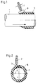
- a tube 1 is mounted in a rotating device, not shown.
- a mixing head 2 with a slot nozzle 3 is arranged to be longitudinally displaceable.
- the feed takes place at a constant speed.
- the slot die is aligned in the longitudinal direction of the tube and thus includes an angle ⁇ of 15 °, and it is arranged above the upwardly rotating quarter of the tube 1 at an angle ⁇ of 85 ° in front of the zenith.
- the applied mixture layer is designated 4.
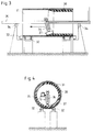
- a tube 31 is mounted on rollers 32 and is rotated by rollers 33.
- a support arm 35 mounted on driven rollers 34 is pushed through the tube 31, to which a mixing head 36 with a slot die 37 is attached.
- This slot die 37 is aligned at the deepest point of the tube 31 in the longitudinal direction of the tube and forms an angle ⁇ of 8 ° with the tube inner wall.
- the applied mixture layer is designated 38.
- a steel roller with a core diameter of 240 mm is sandblasted and coated with a two-component adhesive with approx. 75 g / m2 using rollers.
- the length of the roll is 1,400 mm.
- a 23 mm thick PUR elastomer layer is applied by applying a reaction mixture recipe below using a 125 x 0.6 mm wide slot nozzle.
- the nozzle is clamped in its longitudinal direction parallel to the roller and vertically inclined by 15 ° so that the lower edge hovers approx. 5 mm above the roller surface.
- the point of impact of the reaction mixture is approximately 85 ° to the horizontal axis of the roller.
- the speed is 13 min ⁇ 1, the feed 208 mm / min and the total output 4,270 g / min.
- the reaction mixture corresponds to the following recipe:
- Component A is a compound having Component A:
- Component B is a compound having Component B:
- a steel roller with a core diameter of 260 mm is provided with a 22 mm thick coating.
- the roller speed is 28 min ⁇ 1 and the feed of the slot die at 182 mm / min.
- the angle of attack ⁇ of the slot die was set at 17 °.
- Component A is a compound having Component A:
- Component B is a compound having Component B:
- a polyol amine mixture consisting of 1.5 parts by weight of diethyltoluenediamine with an NH number of 630 and 3.5 parts by weight of a polyether carbonate with an average molecular weight of 2,000.
- Component A is metered in at a temperature of 90 ° C. with an output of 3,000 g / min, component B at a temperature of 25 ° C. with an output of 585 g / min and component C at a temperature of 50 ° C and with an output of 150 g / min.
- An adhesive agent is applied to the freshly sandblasted surface in an amount of 80 g / m2 by spraying and / or rolling.
- the mechanically working mixing head attached to a carrier, equipped with a slot nozzle (100 x 0.6 mm) arranged parallel to the tube is inclined at an angle of 10 ° and at a distance from the lower edge of 5 mm, measured from the inner pipe surface, pulled through the pipe in a horizontal direction at a feed rate of 300 mm / min.
- the tube is clamped in a rotating device and is rotated at a speed of 36 min ⁇ 1.
- the polyol A is metered in at an output of 2860 g / min and the isocyanate prepolymer B is metered out at an output of 2,400 g / min and mixed continuously by stirring.
- the coating process is finished after 17 minutes.
Landscapes
- Engineering & Computer Science (AREA)
- Mechanical Engineering (AREA)
- Life Sciences & Earth Sciences (AREA)
- Wood Science & Technology (AREA)
- Application Of Or Painting With Fluid Materials (AREA)
- Coating Apparatus (AREA)
- Spray Control Apparatus (AREA)
- Moulding By Coating Moulds (AREA)
- Pressure Welding/Diffusion-Bonding (AREA)
- Materials For Medical Uses (AREA)
- Extrusion Moulding Of Plastics Or The Like (AREA)
- Lining Or Joining Of Plastics Or The Like (AREA)
Abstract
Description
- Die Erfindung betrifft ein Verfahren und eine Vorrichtung zum Beschichten eines um eine Achse rotierenden Körpers, wobei zwischen dem Körper und einer ein Polyurethan bildendes Reaktionsgemisch ausstoßenden Düse eine Relativbewegung in Richtung der Rotationsachse stattfindet, so daß der Auftrag in schraubenlinienförmigen Windungen erfolgt.
- Das Beschichten rotierender Körper nach diesem Verfahren ist allgemein bekannt und läßt sich in gleicher Weise für die Herstellung von Hohlkörpern, insbesondere Rohren, anwenden, indem man einen entfernbaren Kern oder Dorn beschichtet.
- Je nach den durch die Parameter, wie Umfangsgeschwindigkeit und Vorschubgeschwindigkeit des Körpers bzw. der Düse, gegebenen Bedingungen treten Schwierigkeiten auf. Insbesondere besteht die Gefahr von Lufteinschlüssen und der ungenügenden Verbindung einzelner Windungen. Deshalb hat man bei der Herstellung von Rohren durch Beschichten eines Kerns schon versucht, das Reaktionsgemisch auf ein Trägerband aufzugeben und dieses um einen Kern zu wickeln, wobei der zwischen den einzelnen Windungen vorhandene Spalt mit Reaktionsgemisch ausgegossen wird (EP 0 523 509 A2). Durch das zusätzliche Vergießen des Spaltes ist natürlich der verfahrenstechnische und maschinelle Aufwand groß. Außerdem ist dieses Verfahren zum Beschichten von Körpern nicht geeignet, weil man auf das Trägerband nicht verzichten kann.
- Es besteht die Aufgabe, das eingangs beschriebene Verfahren so zu verbessern, daß einwandfreie Beschichtungen ökonomisch herstellbar sind.
- Diese Aufgabe wird dadurch gelöst, daß eine Breitschlitzdüse verwendet wird, welche parallel zur Rotationsachse unter einem Winkel α angestellt ist, wobei die Relativbewegung und die Reaktionsgeschwindigkeit des Reaktionsgemisches derart mit der Umfangsgeschwindigkeit des rotierenden Körpers abgestimmt sind, daß die aufeinanderfolgenden Windungen sich schuppenförmig überlappen und sich nahtlos miteinander verbinden. Die Auslaßöffnung der Breitschlitzdüse kann ein Länge/Breite-Verhältnis von 10 bis 300, vorzugsweise 100 bis 250, aufweisen.
- Das neue Verfahren ist besonders geeignet für die Beschichtung von Walzen mit einem Polyurethan-Elastomer, wie sie in der Stahlindustrie, Förder- und Transportindustrie sowie in der Papierindustrie eingesetzt werden. Außerdem lassen sich danach Rohre mit Außenbeschichtung für den industriellen und den Off-Shore-Bereich sowie Rohre mit Innenbeschichtung für die hydraulische Förderung von abrasiven Gütern herstellen. Erforderlichenfalls muß man die zu beschichtenden Flächen vorher mit einem Haftvermittler versehen.
- Es lassen sich aber auch Rohre oder sonstige Hohlkörper nach dem neuen Verfahren herstellen, indem man einen entfernbaren Kern beschichtet. In diesem Fall muß man auf den Kern ein Trennmittel auftragen oder ihn mit einer Trennfolie umwickeln. Schließlich läßt sich das neue Verfahren auch dazu benutzen, Rohre mit einem Wärmedämmantel aus Polyurethan-Hartschaumstoff zu versehen. Gegenüber den bekannten Verfahren ist markant, daß der Auftrag der Windungen nicht nebeneinander, sondern überlappend erfolgt. Eigentlich sind bei diesem Verfahren Lufteinschlüsse zu befürchten und die Gefahr, daß sich die einzelnen Windungen nicht miteinander verbinden, liegt an sich sehr nahe. Umso überraschender ist es, daß sich keine Lufteinschlüsse zeigen und daß die Windungen ohne Bildung einer Haut oder Naht miteinander verfließen und eine ausreichend glatte Oberfläche der Beschichtung bilden. Es hat sich gezeigt, daß das neue Verfahren nicht nur für die Innen- und Außenbeschichtung von rotationssymmetrischen Körpern geeignet ist, sondern daß auch Körper beschichtbar sind, welche über Länge und/oder Querschnitt unterschiedliche Durchmesser aufweisen. Es bietet sich an, das Verfahren mittels einer Programmsteuerung durchzuführen. Bei unregelmäßig profilierten Körpern ist es notwendig, die Breitschlitzdüse stets in gleichem Abstand und unter gleicher Neigung zu der zu beschichtenden Oberfläche des Körpers zu führen. Wegen der Breite der Breitschlitzdüse sind natürlich bezüglich der ungleichmäßigen Geometrie von Körpern Grenzen gesetzt. Auch ist es möglich, durch Verändern des Winkels α an gewünschten Stellen unterschiedliche Beschichtungsdicken zu erzielen.
- Ein wesentlicher Parameter des Verfahrens ist die Austrittsviskosität des Reaktionsgemisches aus der Breitschlitzdüse. Um im Zusammenhang hiermit die gewünschte Beschichtungsdicke zu erhalten, ist es häufig erforderlich, die Düsengeometrie zu ändern. Deswegen kann es notwendig sein, die Breitschlitzdüse gegen eine solche anderer Geometrie auszutauschen oder die Schlitzhöhe und Schlitzbreite einstellbar zu gestalten, was äußerst schwierig sein dürfte, weil das Düseninnere auch entsprechend angepaßt werden müßte.
- Besonders vorteilhaft ist es, Breitschlitzdüsen zu verwenden, welche gewährleisten, daß die Austrittsgeschwindigkeit des Gemisches aus dem Düsenschlitz überall gleich groß ist und daß das austretende Gemisch an jeder Stelle des Schlitzes gleich alt ist.
- Generell gilt, daß bei niedrigen Viskositäten die Schlitzhöhe geringer sein kann, während sie bei höheren Viskositäten größer sein muß. Auf diese Weise läßt sich das Druckgefälle in der Düse relativ niedrig halten, so daß beim Dosieren der Reaktionskomponenten keine Hochdruckmischköpfe erforderlich sind und somit die preisgünstigeren Niederdruckmischköpfe den Anforderungen in der Regel genügen. Allerdings haben Hochdruckmischköpfe gegenüber Niederdruckmischköpfen den Vorteil der Selbstreinigung durch einen Ausstoßkolben.
- Die überlappenden Windungen verbinden sich sowohl physikalisch als auch zumindest zum Teil chemisch. Bei Außenbeschichtungen verursacht die Schwindungsspannung ein Zusammenziehen und wirkt der durch die Exothermie der Reaktion bewirkten thermischen Ausdehnung entgegen. Dadurch entstehen Scherspannungen, welche den beschriebenen Vorgang in der Weise unterstützen, daß sich weder eine Haut noch eine Naht ausbildet.
- Das Verfahren ist geeignet, Körper verschiedenster Durchmesser zu beschichten bzw. herzustellen. Bei großen Durchmessern verwendet man langsamer reagierende Systeme als bei kleineren Durchmessern. Bei der Innenbeschichtung von Körpern sollte man die Exothermie so einstellen, daß sich keine zu hohen Schrumpfspannungen bilden, d.h., man sollte mit möglichst vorreagierten Produkten, mit Prepolymeren, arbeiten.
- Mit dem neuen Verfahren lassen sich auch Systeme verarbeiten, die Füllstoffe enthalten, und zwar vorzugsweise in Form von Glaskugeln, Hohlglaskugeln und Glasfasern bis etwa 6 mm Länge. In die Beschichtung lassen sich aber auch grobmaschige Gewebebänder, Glasfaserrovings, Drähte usw. einarbeiten.
- Vorzugsweise wird der Winkel α dem Winkel der sich beim Beschichten ausbildenden Schulter angepaßt. Vorzugsweise beträgt der Winkel α 5 bis 40°, besonders bevorzugt weniger als 25°.
- Das heißt, da man den Winkel der Schulter berechnen bzw. empirisch ermitteln kann, ist er unter Berücksichtigung der weiteren Parameter vorbekannt, und man stellt den Winkel, unter dem die Breitschlitzdüse zu der zu beschichtenden Oberfläche eingestellt wird, ein. Auf diese Weise wird, abgesehen von dem Moment des Anlaufens bis zum Erreichen der gewünschten Dicke, ein gleichmäßiger Abstand der Düsenöffnung von der Auftragsstelle erreicht. Dieser Abstand beträgt zweckmäßigerweise 1 bis 10 mm.
- Gemäß einer besonders vorteilhaften Durchführungsform des neuen Verfahrens richtet man die Breitschlitzdüse in einer Ebene parallel zur Rotationsachse aus, so daß der Auftragsfilm beim Austritt aus der Düse entsprechend dem Wickelwinkel verstreckt wird.
- Es hat sich gezeigt, daß bei Anwendung dieser Maßnahme eine qualitativ hochwertige Beschichtung erzielbar ist, die frei von Lufteinschlüssen ist.
- Man setzt dabei die Breitschlitzdüse zweckmäßigerweise bei Außenbeschichtung im oberen, nach oben drehenden Viertel an, bei Innenbeschichtung im unteren, nach oben drehenden Viertel. Hierdurch wird das Miteinanderverbinden der Windungen besonders begünstigt.
- Vorzugsweise wird die Umfangsgeschwindigkeit am größten Durchmesser der aufzutragenden Beschichtung kleiner eingestellt, als die Austrittsgeschwindigkeit des Reaktionsgemisches aus der Breitschlitzdüse beträgt.
- Durch diese Maßnahme wird die gefürchtete Bläschenbildung an den Rändern des aufgetragenen Bindungsfilmes vermieden.
- Vorzugsweise werden Reaktionsgemische mit einer Gießzeit von 0,3 Sekunden bis 10 Minuten verarbeitet.
- Es hat sich gezeigt, daß Reaktionsgemische mit dieser Gießzeit besonders gut verarbeitbar sind und im Zusammenhang mit den sonstigen Verfahrensparametern eine Beschichtung mit ausreichend glatter Oberfläche garantieren. Das heißt, die einzelnen, schuppenartig aufeinandergelegten Windungen verbinden sich und verfließen so miteinander, daß eine homogene Beschichtung entsteht.
- Es versteht sich, daß sich die Beschichtungsdicke zu Beginn des Auftragsvorganges erst aufbauen muß. Bei Walzenbeschichtungen benötigt man deshalb immer eine Beschichtungsbreite, welche über die spätere Nutzbreite der Beschichtung so weit hinausgeht, daß der Aufbaubereich und der Abbaubereich der Beschichtungsdicke außerhalb dieser Nutzbreite liegen.
- Die neue Vorrichtung zum Beschichten eines um eine Achse rotierenden Körpers mit einem Polyurethan bildenden Reaktionsgemisch geht aus von einer Lagerung und einem Rotationsantrieb für den Körper sowie einer Breitschlitzdüse, wobei entweder die Breitschlitzdüse mit einem parallel zur Rotationsachse des Körpers wirkenden Vorschubantrieb versehen ist oder dem Körper ein in Richtung parallel zur Rotationsachse wirkender Vorschubantrieb zugeordnet ist.
- Das Neue ist darin zu sehen, daß die Breitschlitzdüse mit der zu beschichtenden Fläche des Körpers einen entgegen der Vorschubrichtung öffnenden spitzen Winkel α einschließt.
- Dabei ergeben sich die im Zusammenhang mit dem neuen Verfahren beschriebenen vorteilhaften Effekte.
- In der Zeichnung ist die neue Vorrichtung in einem Ausführungsbeispiel für Rohraußenbeschichtung und in einem Ausführungsbeispiel für Rohrinnenbeschichtung rein schematisch dargestellt und nachstehend näher erläutert. Es zeigen:
- Fig. 1 Die Vorrichtung für Rohraußenbeschichtung im Längsschnitt,
- Fig. 2 die gleiche Vorrichtung in der Stirnansicht,
- Fig. 3 die Vorrichtung für Rohrinnenbeschichtung im Längsschnitt und
- Fig. 4 die gleiche Vorrichtung in der Stirnansicht.
- In Fig. 1 und 2 ist ein Rohr 1 in einer nicht dargestellten Rotationsvorrichtung gelagert. In Richtung der Längsachse dieses Rohres 1 ist ein Mischkopf 2 mit einer Breitschlitzdüse 3 längs verschiebbar angeordnet. Der Vorschub erfolgt mit gleichbleibender Geschwindigkeit. Die Breitschlitzdüse ist in Rohrlängsrichtung ausgerichtet und schließt damit einen Winkel α von 15° ein, und sie ist über dem nach oben drehenden Viertel des Rohres 1 unter einem Winkel β von 85° vor dem Zenit angeordnet. Die aufgetragene Gemischschicht ist mit 4 bezeichnet.
- In Fig. 3 und 4 ist ein Rohr 31 auf Rollen 32 gelagert und wird von Rollen 33 in Rotation versetzt. Durch das Rohr 31 wird ein auf angetriebenen Rollen 34 gelagerter Tragarm 35 geschoben, an welchem ein Mischkopf 36 mit einer Breitschlitzdüse 37 befestigt ist. Diese Breitschlitzdüse 37 ist an der tiefsten Stelle des Rohres 31 in Rohrlängsrichtung ausgerichtet und schließt mit der Rohrinnenwandung einen Winkel α von 8° ein. Die aufgetragene Gemischschicht ist mit 38 bezeichnet.
- Eine Stahlwalze mit einem Kerndurchmesser von 240 mm wird sandgestrahlt und mit einem Zweikomponenten-Haftvermittler mit ca. 75 g/m² mittels Rollen beschichtet. Die Bahnlänge der Walze beträgt 1.400 mm.
- Es wird eine 23 mm dicke PUR-Elastomerschicht durch Auftragen eines Reaktionsgemisches nachstehender Rezeptur mittels einer Breitschlitzdüse von 125 x 0,6 mm aufgetragen. Die Düse ist in ihrer Längsrichtung parallel zur Walze und senkrecht um 15° geneigt so eingespannt, daß die untere Kante ca. 5 mm über der Walzenoberfläche schwebt. Der Auftreffpunkt des Reaktionsgemisches liegt bei ca. 85° zur waagerechten Achse der Walze. Die Drehzahl beträgt 13 min⁻¹, der Vorschub 208 mm/min und der Gesamtausstoß 4.270 g/min.
- Das Reaktionsgemisch entspricht folgender Rezeptur:
- 85 Gew.-Teile Polyether aus Trimethylpropan, Propylenoxid (85 Gew.-%) und Ethylenoxid (15 Gew.-%), OH-Zahl 35
15 Gew.-Teile Diethyltoluylendiamin (Isomerengemisch)
0,05 Gew.-Teile Diazabicyclooctan
Viskosität (25°): 1.050 mPas - Reaktionsprodukt aus:
100 Gew.-Teilen Polyether aus 1,2-Propylenglykol und Propylenoxid, OH-Zahl 56
79 Gew.-Teilen Diphenylmethandiisocyanat (70 Gew.-% 4,4'-MDI, 30 Gew.-% 2,4'-MDI)
NCO-Gehalt: 12,2 %
Viskosität (25°): 1.600 mPas
Mischungsverhältnis
100 Gew.-Teile Komponente A
84 Gew.-Teile Komponente B
Topfzeit: 5 Sekunden
Eigenschaften des Elastomers:
Härte (Shore A) 90
Zugfestigkeit (MPa) 20
Reißdehnung (%) 450
- Eine Stahlwalze mit einem Kerndurchmesser von 260 mm wird mit einer 22 mm dicken Beschichtung versehen. Die Walzendrehzahl liegt bei 28 min⁻¹ und der Vorschub der Breitschlitzdüse bei 182 mm/min. Der Anstellwinkel α der Breitschlitzdüse wurde mit 17° eingestellt.
- Es wird folgende Rezeptur verwendet:
- 100 Gew.-Teile eines Prepolymeren mit 9,8 Gew.-% NCO, bestehend aus 4,4'-Diphenylmethandiisocyanat und einem Polyethercarbonat mit einem mittleren Molgewicht von 2.000
- 19,5 Gew.-Teile eines Diamins 3,5-Bis-thiomethyl-toluylendiamin (überwiegend 2,4-Diaminoverbindung)
- 5 Gew.-Teile eines Polyol-Amingemisches bestehend aus
1,5 Gew.-Teilen Diethyltoluylendiamin mit einer NH-Zahl von 630 und
3,5 Gew.-Teilen eines Polyethercarbonats mit einem mittleren Molekulargewicht von 2.000. - Dabei wird die Komponente A mit einer Temperatur von 90°C mit einem Ausstoß von 3.000 g/min dosiert, die Komponente B mit einer Temperatur von 25°C mit einem Ausstoß von 585 g/min und die Komponente C mit einer Temperatur von 50°C und mit einem Ausstoß von 150 g/min.
- Zur Ausrüstung eines Stahlrohrs der Nennweite 360 mm und einer Länge von 5.000 mm mit einer 15 mm starken Verschleißschutz-Innenbeschichtung wird wie folgt verfahren:
Es wird die gleiche Rezeptur wie in Beispiel 1 verwendet. - Auf die frisch sandgestrahlte Oberfläche wird ein Haftvermittler in einer Menge von 80 g/m² durch Sprühen und/oder Rollen aufgetragen. Nach der vorgeschriebenen Ablüftzeit von einer Stunde wird der an einem Träger befestigte, mechanisch arbeitende Mischkopf, bestückt mit einer parallel zum Rohr angeordneten Breitschlitzdüse (100 x 0,6 mm), in einem Winkel von 10° geneigt und in einem Abstand der Unterkante von 5 mm, gemessen von der inneren Rohroberfläche, in horizontaler Richtung mit einer Vorschubgeschwindigkeit von 300 mm/min durch das Rohr gezogen. Das Rohr ist in eine Drehvorrichtung gespannt und wird mit einer Drehzahl von 36 min⁻¹ rotiert. In der Mischkammer des Mischkopfes werden mit einem Ausstoß von 2860 g/min das Polyol A und mit einem Ausstoß von 2.400 g/min das Isocyanat-Prepolymer B dosiert und durch Rühren kontinuierlich vermischt. Der Beschichtungsvorgang ist nach 17 Minuten beendet.
Claims (6)
- Verfahren zum Beschichten eines um eine Achse rotierenden Körpers (1, 31), wobei zwischen dem Körper (1, 31) und einer ein Polyurethan bildendes Reaktionsgemisch ausstoßenden Düse (3, 37) eine Relativbewegung in Richtung der Rotationsachse stattfindet, so daß der Auftrag in schraubenlinienförmigen Windungen erfolgt, dadurch gekennzeichnet, daß eine Breitschlitzdüse (3, 37) verwendet wird, welche parallel zur Rotationsachse unter einem Winkel α angestellt ist, und wobei die Reaktionsgeschwindigkeit des Reaktionsgemisches und die Relativbewegung derart mit der Umfangsgeschwindigkeit des rotierenden Körpers (1, 31) abgestimmt sind, daß die aufeinanderfolgenden Windungen sich schuppenförmig überlappen und sich nahtlos miteinander verbinden.
- Verfahren nach Anspruch 1, dadurch gekennzeichnet, daß der Winkel α dem Winkel der sich beim Beschichten ausbildenden Schulter angepaßt wird.
- Verfahren nach Anspruch 1 oder 2, dadurch gekennzeichnet, daß die Umfangsgeschwindigkeit am größten Durchmesser der aufzutragenden Beschichtung kleiner eingestellt wird, als die Austrittsgeschwindigkeit des Reaktionsgemisches aus der Breitschlitzdüse (1, 37) beträgt.
- Verfahren nach einem der Ansprüche 1 bis 3, dadurch gekennzeichnet, daß Reaktionsgemische mit einer Gießzeit von 0,3 Sekunden bis 10 Minuten verarbeitet werden.
- Vorrichtung zum Beschichten eines um eine Achse rotierenden Körpers (1, 31) mit einem Polyurethan bildenden Reaktionsgemisch, bestehend aus einer Lagerung und einem Rotationsantrieb für den Körper (33) sowie aus einer Breitschlitzdüse (3, 37), wobei entweder die Breitschlitzdüse (3, 37) mit einem parallel zur Rotationsachse des Körpers (1, 31) wirkenden Vorschubantrieb versehen ist oder dem Körper (1, 31) ein in Richtung parallel zur Rotationsachse wirkender Vorschubantrieb zugeordnet ist, dadurch gekennzeichnet, daß die Breitschlitzdüse (3, 37) mit der zu beschichtenden Fläche des Körpers (1, 31) einen entgegen der Vorschubrichtung öffnenden, spitzen Winkel α einschließt.
- Vorrichtung nach Anspruch 5, dadurch gekennzeichnet, daß die Breitschlitzdüse (3, 37) in einer Ebene parallel zur Rotationsachse ausgerichtet ist.
Applications Claiming Priority (2)
| Application Number | Priority Date | Filing Date | Title |
|---|---|---|---|
| DE4325653 | 1993-07-30 | ||
| DE4325653A DE4325653C2 (de) | 1993-07-30 | 1993-07-30 | Verfahren und Vorrichtung zum Beschichten eines um eine Achse rotierenden Körpers |
Publications (3)
| Publication Number | Publication Date |
|---|---|
| EP0636467A2 true EP0636467A2 (de) | 1995-02-01 |
| EP0636467A3 EP0636467A3 (de) | 1995-07-26 |
| EP0636467B1 EP0636467B1 (de) | 1999-02-10 |
Family
ID=6494111
Family Applications (1)
| Application Number | Title | Priority Date | Filing Date |
|---|---|---|---|
| EP94111134A Expired - Lifetime EP0636467B1 (de) | 1993-07-30 | 1994-07-18 | Verfahren und Vorrichtung zum Beschichten eines um eine Achse rotierenden Körpers |
Country Status (15)
| Country | Link |
|---|---|
| EP (1) | EP0636467B1 (de) |
| JP (1) | JP3683601B2 (de) |
| KR (1) | KR100286878B1 (de) |
| AT (1) | ATE176621T1 (de) |
| AU (1) | AU675716B2 (de) |
| BR (1) | BR9402997A (de) |
| CA (1) | CA2128837C (de) |
| DE (2) | DE4325653C2 (de) |
| DK (1) | DK0636467T3 (de) |
| ES (1) | ES2127855T3 (de) |
| FI (1) | FI108849B (de) |
| GR (1) | GR3029484T3 (de) |
| NO (1) | NO309027B1 (de) |
| RU (1) | RU2119831C1 (de) |
| ZA (1) | ZA945636B (de) |
Cited By (7)
| Publication number | Priority date | Publication date | Assignee | Title |
|---|---|---|---|---|
| EP0685314A1 (de) * | 1994-05-31 | 1995-12-06 | Welex Incorporated | Verfahren und Vorrichtung zum Auspressen und Kühlen von Kunststofffolie |
| EP0765694A1 (de) * | 1995-09-22 | 1997-04-02 | Dai Nippon Printing Co., Ltd. | Verfahren und Anlage zum Düsebeschichten |
| EP1470868A2 (de) | 2003-04-25 | 2004-10-27 | Voith Paper Patent GmbH | Verfahren zur Beschichtung eines zylindrischen Körpers |
| US20080034998A1 (en) * | 2006-08-08 | 2008-02-14 | Byers Joseph L | Method of making a printing blanket or sleeve including cast polyurethane layers |
| US7390867B2 (en) | 2002-12-17 | 2008-06-24 | Basf Se | Isocyanate adducts |
| DE102011084776A1 (de) | 2010-10-26 | 2012-04-26 | Metso Paper, Inc. | Verfahren zur Herstellung einer Faserbahnmaschinenwalze und Faserbahnmaschinenwalze |
| CN113085130A (zh) * | 2021-04-07 | 2021-07-09 | 武汉宏绅耀贸易有限公司 | 一种光纤制造外护套挤塑成型加工设备及成型加工方法 |
Families Citing this family (7)
| Publication number | Priority date | Publication date | Assignee | Title |
|---|---|---|---|---|
| DE4436534A1 (de) | 1994-10-13 | 1996-04-18 | Bayer Ag | Verfahren und Vorrichtung zur Beschichtung von Rotationskörpern mit nicht geradlinig verlaufender Achse |
| KR100924656B1 (ko) | 2007-11-19 | 2009-11-03 | 한국전기연구원 | 원통형 기판용 스핀 코터 및 이를 이용한 코팅방법 |
| DE202009007391U1 (de) | 2009-05-23 | 2009-08-13 | Kraussmaffei Technologies Gmbh | Vorrichtung zum Auftragen eines Kunststoffmaterials auf die Oberfläche eines Rohrkörpers |
| DE102018204068A1 (de) | 2017-03-17 | 2018-09-20 | Haverkamp Gmbh | Verfahren zum Beschichten einer Rohrinnenfläche und Rohr mit einer beschichteten Rohrinnenfläche |
| RU2687456C1 (ru) * | 2018-07-11 | 2019-05-13 | Акционерное общество "Научно-производственное объединение "СПЛАВ" | Способ формирования покрытия внутри вращающейся вокруг оси оболочки |
| JP6968771B2 (ja) * | 2018-09-13 | 2021-11-17 | 三菱重工業株式会社 | 粘性体塗布装置 |
| CN112827729B (zh) * | 2021-01-06 | 2022-05-17 | 烟台世德装备股份有限公司 | 一种铸造件喷漆装置 |
Family Cites Families (7)
| Publication number | Priority date | Publication date | Assignee | Title |
|---|---|---|---|---|
| CA945019A (en) * | 1971-06-23 | 1974-04-09 | Elast-O-Cor Products And Engineering Limited | Casting plastics material on the interior of hollow shells |
| US4366972A (en) * | 1981-04-02 | 1983-01-04 | Ameron-Price Company | Pipe coating system |
| DE3145122C2 (de) * | 1981-11-13 | 1984-11-29 | Manfred 5210 Troisdorf Hawerkamp | Vorrichtung zum Herstellen eines Rohres od. dgl. aus einem stranggepreßten thermoplastischen Kunststoffprofil |
| JPS60150053A (ja) * | 1984-01-18 | 1985-08-07 | Konishiroku Photo Ind Co Ltd | 電子写真感光体基材等の塗布方法 |
| JPS62266175A (ja) * | 1986-05-12 | 1987-11-18 | Konika Corp | 塗布方法 |
| DE3828427A1 (de) * | 1988-08-22 | 1990-03-08 | Roehrenwerk Gebr Fuchs Gmbh | Verfahren und vorrichtung zum umhuellen von mit einem thermoplastischen kunststoff beschichteten stahlrohren mit einer zusaetzlichen schutzschicht aus einer hydraulisch abbindenden masse wie zementmoertel |
| DE4123920C2 (de) * | 1991-07-19 | 1994-04-14 | Bayer Ag | Verfahren und Vorrichtung zum Herstellen von gewickelten Rohren |
-
1993
- 1993-07-30 DE DE4325653A patent/DE4325653C2/de not_active Expired - Fee Related
-
1994
- 1994-07-18 AT AT94111134T patent/ATE176621T1/de active
- 1994-07-18 DE DE59407790T patent/DE59407790D1/de not_active Expired - Lifetime
- 1994-07-18 EP EP94111134A patent/EP0636467B1/de not_active Expired - Lifetime
- 1994-07-18 DK DK94111134T patent/DK0636467T3/da active
- 1994-07-18 ES ES94111134T patent/ES2127855T3/es not_active Expired - Lifetime
- 1994-07-26 CA CA002128837A patent/CA2128837C/en not_active Expired - Lifetime
- 1994-07-26 AU AU68699/94A patent/AU675716B2/en not_active Expired
- 1994-07-28 NO NO942811A patent/NO309027B1/no not_active IP Right Cessation
- 1994-07-28 FI FI943547A patent/FI108849B/fi not_active IP Right Cessation
- 1994-07-28 JP JP19463194A patent/JP3683601B2/ja not_active Expired - Lifetime
- 1994-07-29 RU RU94027586A patent/RU2119831C1/ru active
- 1994-07-29 ZA ZA945636A patent/ZA945636B/xx unknown
- 1994-07-29 BR BR9402997A patent/BR9402997A/pt not_active IP Right Cessation
- 1994-07-29 KR KR1019940018617A patent/KR100286878B1/ko not_active Expired - Lifetime
-
1999
- 1999-02-24 GR GR990400581T patent/GR3029484T3/el unknown
Cited By (9)
| Publication number | Priority date | Publication date | Assignee | Title |
|---|---|---|---|---|
| EP0685314A1 (de) * | 1994-05-31 | 1995-12-06 | Welex Incorporated | Verfahren und Vorrichtung zum Auspressen und Kühlen von Kunststofffolie |
| EP0765694A1 (de) * | 1995-09-22 | 1997-04-02 | Dai Nippon Printing Co., Ltd. | Verfahren und Anlage zum Düsebeschichten |
| US7390867B2 (en) | 2002-12-17 | 2008-06-24 | Basf Se | Isocyanate adducts |
| EP1470868A2 (de) | 2003-04-25 | 2004-10-27 | Voith Paper Patent GmbH | Verfahren zur Beschichtung eines zylindrischen Körpers |
| EP1470868A3 (de) * | 2003-04-25 | 2006-02-08 | Voith Paper Patent GmbH | Verfahren zur Beschichtung eines zylindrischen Körpers |
| US20080034998A1 (en) * | 2006-08-08 | 2008-02-14 | Byers Joseph L | Method of making a printing blanket or sleeve including cast polyurethane layers |
| DE102011084776A1 (de) | 2010-10-26 | 2012-04-26 | Metso Paper, Inc. | Verfahren zur Herstellung einer Faserbahnmaschinenwalze und Faserbahnmaschinenwalze |
| CN113085130A (zh) * | 2021-04-07 | 2021-07-09 | 武汉宏绅耀贸易有限公司 | 一种光纤制造外护套挤塑成型加工设备及成型加工方法 |
| CN113085130B (zh) * | 2021-04-07 | 2022-08-26 | 深圳市旭辉发光通讯科技有限公司 | 一种光纤制造外护套挤塑成型加工设备及成型加工方法 |
Also Published As
| Publication number | Publication date |
|---|---|
| RU94027586A (ru) | 1996-08-10 |
| NO309027B1 (no) | 2000-12-04 |
| FI943547L (fi) | 1995-01-31 |
| EP0636467A3 (de) | 1995-07-26 |
| EP0636467B1 (de) | 1999-02-10 |
| DK0636467T3 (da) | 1999-09-20 |
| NO942811D0 (no) | 1994-07-28 |
| AU6869994A (en) | 1995-02-09 |
| FI943547A0 (fi) | 1994-07-28 |
| DE59407790D1 (de) | 1999-03-25 |
| JPH0760186A (ja) | 1995-03-07 |
| NO942811L (no) | 1995-01-31 |
| RU2119831C1 (ru) | 1998-10-10 |
| FI108849B (fi) | 2002-04-15 |
| KR100286878B1 (ko) | 2001-04-16 |
| CA2128837A1 (en) | 1995-01-31 |
| ES2127855T3 (es) | 1999-05-01 |
| DE4325653A1 (de) | 1995-02-02 |
| KR950002869A (ko) | 1995-02-16 |
| JP3683601B2 (ja) | 2005-08-17 |
| AU675716B2 (en) | 1997-02-13 |
| ZA945636B (en) | 1995-03-07 |
| CA2128837C (en) | 2004-07-06 |
| BR9402997A (pt) | 1995-04-11 |
| GR3029484T3 (en) | 1999-05-28 |
| DE4325653C2 (de) | 1995-07-20 |
| ATE176621T1 (de) | 1999-02-15 |
Similar Documents
| Publication | Publication Date | Title |
|---|---|---|
| EP0636467B1 (de) | Verfahren und Vorrichtung zum Beschichten eines um eine Achse rotierenden Körpers | |
| DE3336707C2 (de) | Verfahren und Vorrichtung zum Auftragen eines verschleißfesten Überzuges auf ein dünnes, metallisches, bandförmiges Trägermaterial, insbesondere zur Herstellung von Schabern, Rakeln und dergleichen | |
| EP2661346B1 (de) | Verfahren und vorrichtung zum auftrag von flüssigen reaktionsgemischen auf eine deckschicht | |
| EP0166245A2 (de) | Verfahren und Vorrichtung zum kontinuierlichen Herstellen von länglichen Hohlkörpern, insbesondere von Schläuchen, Rohren oder Innenlinern für solche, aus einem flüssigen Material, wie Reaktionsgemisch oder Schmelze | |
| DE3029288A1 (de) | Mit einem elastomeren material bedeckte walzen und verfahren zu ihrer herstellung | |
| US5601881A (en) | Method and device for coating a body rotating about an axis | |
| DE3929820C1 (de) | ||
| DE60004489T2 (de) | Verfahren zur herstellung eines schabers mit weicher spitze | |
| DE69915607T3 (de) | Verfahren zur beschichtung eines press- oder übertragungsbandes und beschichtetes band | |
| DE3827486C2 (de) | ||
| EP0401551B1 (de) | Verfahren und Werkstoff zur Beschichtung von Schalplatten | |
| WO2019007650A1 (de) | Pressmantel und dessen verwendung sowie verfahren zur herstellung des pressmantels | |
| EP0791118B1 (de) | Vorrichtung zum beschichten von flächen an gebäuden mittels aushärtbarer dickstoffe | |
| DE3828427C2 (de) | ||
| EP2391465B1 (de) | Vorrichtung und verfahren zum aufhaspeln eines bandes mit veränderlicher banddicke, insbesondere eines metallbandes | |
| DE60318956T2 (de) | Verfahren und vorrichtung zum auftragen einer beschichtigung auf einen um eine achse rotierenden körper | |
| DE2401664A1 (de) | Verfahren zur harzablagerung auf einem sich drehenden dorn, insbesondere zum aufbringen einer beschichtung aus glasfaserverstaerktem polyesterharz | |
| DE1635671A1 (de) | Verfahren und Vorrichtung zum UEberziehen eines schlauchfoermigen Gewebes oder Gewirkes mit einem fluessigen UEberzugsmaterial | |
| DE69121437T2 (de) | Verfahren zur Herstellung eines Schlauches mit geringer Permeabilität | |
| DE19636801A1 (de) | Verfahren und Anlage zum Mattieren der Oberfläche von Edelstahlblechen | |
| DE19741523A1 (de) | Kontinuierliches Verfahren zur Herstellung von flächigen Schaumstoffplatten und Vorrichtung zur Durchführung des Verfahrens | |
| EP1882812B1 (de) | Vorrichtung und Verfahren zum Auftragen einer abbindbaren Schicht auf Wandungen von Bauteilen | |
| DE3909935C2 (de) | Verfahren und Vorrichtung zum Herstellen eines undurchlässigen und biegsamen Bandes oder Schlauches | |
| AT524539B1 (de) | Verfahren zum Haspeln eines metallischen Bandes, Coil und Haspeleinrichtung | |
| DE4431113A1 (de) | Verfahren und Vorrichtung zum Auftragen einer Beschichtungsmasse auf Glasflaschen |
Legal Events
| Date | Code | Title | Description |
|---|---|---|---|
| PUAI | Public reference made under article 153(3) epc to a published international application that has entered the european phase |
Free format text: ORIGINAL CODE: 0009012 |
|
| AK | Designated contracting states |
Kind code of ref document: A2 Designated state(s): AT BE DE DK ES FR GB GR IT NL SE |
|
| PUAL | Search report despatched |
Free format text: ORIGINAL CODE: 0009013 |
|
| AK | Designated contracting states |
Kind code of ref document: A3 Designated state(s): AT BE DE DK ES FR GB GR IT NL SE |
|
| 17P | Request for examination filed |
Effective date: 19960110 |
|
| 17Q | First examination report despatched |
Effective date: 19970513 |
|
| GRAG | Despatch of communication of intention to grant |
Free format text: ORIGINAL CODE: EPIDOS AGRA |
|
| GRAG | Despatch of communication of intention to grant |
Free format text: ORIGINAL CODE: EPIDOS AGRA |
|
| GRAH | Despatch of communication of intention to grant a patent |
Free format text: ORIGINAL CODE: EPIDOS IGRA |
|
| GRAH | Despatch of communication of intention to grant a patent |
Free format text: ORIGINAL CODE: EPIDOS IGRA |
|
| GRAA | (expected) grant |
Free format text: ORIGINAL CODE: 0009210 |
|
| AK | Designated contracting states |
Kind code of ref document: B1 Designated state(s): AT BE DE DK ES FR GB GR IT NL SE |
|
| REF | Corresponds to: |
Ref document number: 176621 Country of ref document: AT Date of ref document: 19990215 Kind code of ref document: T |
|
| GBT | Gb: translation of ep patent filed (gb section 77(6)(a)/1977) |
Effective date: 19990210 |
|
| REF | Corresponds to: |
Ref document number: 59407790 Country of ref document: DE Date of ref document: 19990325 |
|
| ITF | It: translation for a ep patent filed | ||
| REG | Reference to a national code |
Ref country code: ES Ref legal event code: FG2A Ref document number: 2127855 Country of ref document: ES Kind code of ref document: T3 |
|
| ET | Fr: translation filed | ||
| REG | Reference to a national code |
Ref country code: DK Ref legal event code: T3 |
|
| PLBE | No opposition filed within time limit |
Free format text: ORIGINAL CODE: 0009261 |
|
| STAA | Information on the status of an ep patent application or granted ep patent |
Free format text: STATUS: NO OPPOSITION FILED WITHIN TIME LIMIT |
|
| 26N | No opposition filed | ||
| REG | Reference to a national code |
Ref country code: GB Ref legal event code: IF02 |
|
| PGFP | Annual fee paid to national office [announced via postgrant information from national office to epo] |
Ref country code: IT Payment date: 20130626 Year of fee payment: 20 Ref country code: GR Payment date: 20130620 Year of fee payment: 20 |
|
| PGFP | Annual fee paid to national office [announced via postgrant information from national office to epo] |
Ref country code: DK Payment date: 20130711 Year of fee payment: 20 Ref country code: ES Payment date: 20130628 Year of fee payment: 20 Ref country code: AT Payment date: 20130626 Year of fee payment: 20 Ref country code: NL Payment date: 20130716 Year of fee payment: 20 Ref country code: BE Payment date: 20130712 Year of fee payment: 20 Ref country code: SE Payment date: 20130711 Year of fee payment: 20 Ref country code: DE Payment date: 20130711 Year of fee payment: 20 |
|
| PGFP | Annual fee paid to national office [announced via postgrant information from national office to epo] |
Ref country code: FR Payment date: 20130724 Year of fee payment: 20 Ref country code: GB Payment date: 20130717 Year of fee payment: 20 |
|
| REG | Reference to a national code |
Ref country code: DE Ref legal event code: R071 Ref document number: 59407790 Country of ref document: DE |
|
| REG | Reference to a national code |
Ref country code: DK Ref legal event code: EUP Effective date: 20140718 |
|
| REG | Reference to a national code |
Ref country code: NL Ref legal event code: V4 Effective date: 20140718 |
|
| BE20 | Be: patent expired |
Owner name: *BAYER A.G. Effective date: 20140718 |
|
| REG | Reference to a national code |
Ref country code: GB Ref legal event code: PE20 Expiry date: 20140717 |
|
| REG | Reference to a national code |
Ref country code: AT Ref legal event code: MK07 Ref document number: 176621 Country of ref document: AT Kind code of ref document: T Effective date: 20140718 |
|
| REG | Reference to a national code |
Ref country code: SE Ref legal event code: EUG |
|
| REG | Reference to a national code |
Ref country code: GR Ref legal event code: MA Ref document number: 990400581 Country of ref document: GR Effective date: 20140719 |
|
| PG25 | Lapsed in a contracting state [announced via postgrant information from national office to epo] |
Ref country code: DE Free format text: LAPSE BECAUSE OF EXPIRATION OF PROTECTION Effective date: 20140719 |
|
| REG | Reference to a national code |
Ref country code: ES Ref legal event code: FD2A Effective date: 20141120 |
|
| PG25 | Lapsed in a contracting state [announced via postgrant information from national office to epo] |
Ref country code: GB Free format text: LAPSE BECAUSE OF EXPIRATION OF PROTECTION Effective date: 20140717 |
|
| PG25 | Lapsed in a contracting state [announced via postgrant information from national office to epo] |
Ref country code: ES Free format text: LAPSE BECAUSE OF EXPIRATION OF PROTECTION Effective date: 20140719 |