EP0765694A1 - Verfahren und Anlage zum Düsebeschichten - Google Patents
Verfahren und Anlage zum Düsebeschichten Download PDFInfo
- Publication number
- EP0765694A1 EP0765694A1 EP96115179A EP96115179A EP0765694A1 EP 0765694 A1 EP0765694 A1 EP 0765694A1 EP 96115179 A EP96115179 A EP 96115179A EP 96115179 A EP96115179 A EP 96115179A EP 0765694 A1 EP0765694 A1 EP 0765694A1
- Authority
- EP
- European Patent Office
- Prior art keywords
- nozzle
- coating
- coated
- workpiece
- liquid vessel
- Prior art date
- Legal status (The legal status is an assumption and is not a legal conclusion. Google has not performed a legal analysis and makes no representation as to the accuracy of the status listed.)
- Granted
Links
- 238000000576 coating method Methods 0.000 title claims abstract description 196
- 239000011248 coating agent Substances 0.000 claims abstract description 177
- 239000007788 liquid Substances 0.000 claims abstract description 44
- 239000011521 glass Substances 0.000 claims abstract description 41
- 230000004888 barrier function Effects 0.000 claims abstract description 33
- 238000001035 drying Methods 0.000 claims description 22
- 230000015572 biosynthetic process Effects 0.000 claims description 7
- 239000002904 solvent Substances 0.000 claims description 5
- 230000000977 initiatory effect Effects 0.000 claims description 3
- 230000009471 action Effects 0.000 claims description 2
- 230000008016 vaporization Effects 0.000 claims description 2
- 238000000034 method Methods 0.000 abstract description 11
- 239000000463 material Substances 0.000 description 7
- 238000007650 screen-printing Methods 0.000 description 7
- 238000007639 printing Methods 0.000 description 6
- 230000008569 process Effects 0.000 description 6
- 238000000059 patterning Methods 0.000 description 4
- 230000002093 peripheral effect Effects 0.000 description 4
- 230000004048 modification Effects 0.000 description 3
- 238000012986 modification Methods 0.000 description 3
- 238000005488 sandblasting Methods 0.000 description 3
- 238000009432 framing Methods 0.000 description 2
- 238000000206 photolithography Methods 0.000 description 2
- 230000003746 surface roughness Effects 0.000 description 2
- OAICVXFJPJFONN-UHFFFAOYSA-N Phosphorus Chemical compound [P] OAICVXFJPJFONN-UHFFFAOYSA-N 0.000 description 1
- 230000004075 alteration Effects 0.000 description 1
- 239000006185 dispersion Substances 0.000 description 1
- 230000000694 effects Effects 0.000 description 1
- 230000008030 elimination Effects 0.000 description 1
- 238000003379 elimination reaction Methods 0.000 description 1
- 230000002708 enhancing effect Effects 0.000 description 1
- 239000004744 fabric Substances 0.000 description 1
- 239000004973 liquid crystal related substance Substances 0.000 description 1
- 238000004519 manufacturing process Methods 0.000 description 1
- 230000000873 masking effect Effects 0.000 description 1
- 238000005192 partition Methods 0.000 description 1
- 239000000843 powder Substances 0.000 description 1
- 230000005855 radiation Effects 0.000 description 1
Images


Classifications
-
- B—PERFORMING OPERATIONS; TRANSPORTING
- B05—SPRAYING OR ATOMISING IN GENERAL; APPLYING FLUENT MATERIALS TO SURFACES, IN GENERAL
- B05D—PROCESSES FOR APPLYING FLUENT MATERIALS TO SURFACES, IN GENERAL
- B05D1/00—Processes for applying liquids or other fluent materials
- B05D1/26—Processes for applying liquids or other fluent materials performed by applying the liquid or other fluent material from an outlet device in contact with, or almost in contact with, the surface
-
- C—CHEMISTRY; METALLURGY
- C03—GLASS; MINERAL OR SLAG WOOL
- C03C—CHEMICAL COMPOSITION OF GLASSES, GLAZES OR VITREOUS ENAMELS; SURFACE TREATMENT OF GLASS; SURFACE TREATMENT OF FIBRES OR FILAMENTS MADE FROM GLASS, MINERALS OR SLAGS; JOINING GLASS TO GLASS OR OTHER MATERIALS
- C03C17/00—Surface treatment of glass, not in the form of fibres or filaments, by coating
- C03C17/001—General methods for coating; Devices therefor
- C03C17/002—General methods for coating; Devices therefor for flat glass, e.g. float glass
-
- C—CHEMISTRY; METALLURGY
- C03—GLASS; MINERAL OR SLAG WOOL
- C03C—CHEMICAL COMPOSITION OF GLASSES, GLAZES OR VITREOUS ENAMELS; SURFACE TREATMENT OF GLASS; SURFACE TREATMENT OF FIBRES OR FILAMENTS MADE FROM GLASS, MINERALS OR SLAGS; JOINING GLASS TO GLASS OR OTHER MATERIALS
- C03C17/00—Surface treatment of glass, not in the form of fibres or filaments, by coating
- C03C17/02—Surface treatment of glass, not in the form of fibres or filaments, by coating with glass
- C03C17/04—Surface treatment of glass, not in the form of fibres or filaments, by coating with glass by fritting glass powder
Definitions
- the present invention relates to a method of and an equipment for coating a plate or the like with a coating solution which is discharged from a nozzle. More particularly, it relates to a nozzle coating method and equipment which are well suited for application to the formation of the barrier rib of a plasma display panel.
- a plasma display panel which is a gas discharge panel, has a large number of cells which are sandwiched in between two glass plates and each of which functions as a minute electric discharge space. Each of the cells forms a picture element of predetermined color in such a way that light is emitted by electric discharge or that a phosphor is caused to fluoresce by ultraviolet radiation generated through electric discharge.
- the minute cells are isolated from one another by a barrier rib or partition in order to prevent the crosstalk of light among the individual cells and to hold constant the spacing or gap between the glass plates.
- the barrier rib surrounding each discharge space is required to rise vertically and to be narrow and high, with the intentions of enlarging the discharge space to the utmost and attaining the light emission or fluorescence at a high intensity.
- the barrier rib needs to have a high aspect ratio of, for example, a width of 30 - 50 [ ⁇ m] to a height of 100 [ ⁇ m].
- the thickness of a film which can be formed by one time of printing is, at most, several tens [ ⁇ m]. It is therefore necessary for attaining a desired film thickness (i. e., a desired barrier rib height) to repeat printing and drying a large number of times, in general, ten times or so.
- the coating film which is formed by the screen printing becomes concave at its peripheral part and convex at its central part.
- This incurs the problem that, in the case of overprinting the coating films the large number of times, the slack cross-sectional shapes thereof are inevitably accumulated to spread the bottom part of a finished film. It is therefore limited to fine the pitch of the barrier rib (in other words, to realize the high definition of the display panel).
- the precision of the pitch is limited due to the distortion of the form plate of the screen printing. It is eventually difficult to enlarge the size of the display panel.
- This method is such that, after a barrier rib forming layer has been deposited on a plate, it is overlaid with a resist pattern for the subtractive process by printing or photolithography, whereupon a barrier rib forming material is removed in correspondence with the openings of a resist in the resist pattern.
- sandblasting is well suited as one of expedients for the removal.
- the barrier rib material is physically etched by jetting fine grains mixed in compressed air, at high velocity.
- This expedient is capable of working the barrier rib material into the desirable shape in which the wall of a barrier rib rises vertically and is narrow and high.
- the photolithography is adopted for patterning the resist, there are the merits that the precision of the pattern can be heightened and that the size of a panel can be enlarged.
- the barrier rib forming layer which is not baked yet needs to be first deposited at a film thickness which is uniform over the whole surface of the glass plate within the effective display area of the panel.
- the barrier rib forming layer has been deposited in such a way that the barrier rib forming material turned into ink is directly applied onto the glass plate by blade coating or by multilayer printing based on the screen printing.
- the multilayer screen printing is inferior in productivity because the steps of allover printing or smearing - subsequent drying are usually repeated five - ten times. Another problem is that ruggedness appears in the surface of the coating film due to the loose texture of raw silk cloth which is used in the printing.
- the glass plate which is produced by floating and which is not polished is usually used in the plasma display panel. Therefore, the glass plate involves a dispersion of or above 20 [ ⁇ m] in its plate thickness.
- the barrier rib forming material is applied onto the glass plate by a coating process such as the blade coating or roll coating, the thickness of the coating film is affected by the thickness of the glass plate. It is accordingly difficult to deposit the barrier rib forming layer having the uniform film thickness.
- the film thickness of the barrier rib forming layer after having been dried is as great as 150 [ ⁇ m] - 200 [ ⁇ m]. This incurs the problem that the framing of the peripheral part of the barrier rib forming layer attributed to the drying step is difficult to be eliminated merely by one time of application, and that the elimination of the framing necessitates to apply the barrier rib forming material a plurality of number of times even with the coating process.
- barrier rib forming layer in order to execute the patterning, alignment marks necessary for registration at the step of exposing the resist to light must be kept denuded without being covered with the barrier rib forming layer. It is therefore desirable to deposit the barrier rib forming layer in the state in which a non-coated area is left at the outer peripheral part of the glass plate. It is very difficult, however, to perform such an applying operation with any process other than the screen printing, for example, the coating process.
- the present invention has been made in view of the problems of the prior art as stated above, and has for its object to provide a nozzle coating method and equipment according to which a coated surface having a required film thickness and involving little surface ruggedness to exhibit uniformity in the film thickness up to the peripheral part of the coated surface can be formed in only a required area by one time of coating.
- Another object of the present invention is to provide a nozzle coating method and equipment according to which the single equipment can be used for coating without any alteration even when the size of a glass plate or the like has changed, and only a part of a glass plate or the like can be coated with a pattern without masking or the like.
- a nozzle coating method comprising the step of coating a planar surface to-be-coated of a workpiece with a coating solution in parallel coating lines in such a way that a nozzle is moved relatively to and in parallel with the surface to-be-coated while the coating solution is being discharged from a tip of the nozzle in a state in which the nozzle tip is spaced from the surface to-be-coated, and the step of iteratively coating the surface to-be-coated in succession in such a manner that a part of a next coating line in a widthwise direction thereof overlaps the previous coating line in the widthwise direction, thereby to form a coated surface.
- a gap between the surface to-be-coated and the nozzle tip may well be set substantially equal to a desired film thickness of the coated surface.
- a gap between the surface to-be-coated and the nozzle tip may well be set larger than a desired film thickness of the coated surface, and the coating lines are formed by the use of the coating solution which dangles in the shape of a thread from the nozzle.
- a gap between the surface to-be-coated and the nozzle tip may well be set smaller than a desired film thickness of the coated surface.
- the discharge of the coating solution from the nozzle tip may well be suspended while the nozzle is shifted from a terminating end of one of the coating lines to an initiating end of a next one of the coating lines.
- a widthwise pitch of the coating lines may well be set depending upon a diameter of a discharge port of the nozzle, a discharge pressure of the coating solution at the discharge port, and properties of the coating solution including a viscosity and a surface tension.
- the nozzle and at least one other nozzle may well be so arranged that the plurality of nozzles are spaced at a predetermined interval which is integral times a widthwise pitch of the coating lines, in the widthwise direction of the coating lines, and the surface to-be-coated may well be coated by moving the individual nozzles relatively thereto in such a manner that a first one of the coating lines based on a certain one of the individual nozzles and a last one of the coating lines based on another of the individual nozzles adjoining the certain nozzle rearward of the certain nozzle in the widthwise pitch feed direction thereof overlap each other in the widthwise direction.
- the coating solution contains a solvent
- the coated surface is let stand in a temperature environment for a predetermined time period after the formation of the coated surface and before final drying for vaporizing the contained solvent which remains in the coated surface, the temperature environment having a temperature lower than that of the final drying and being capable of lowering a viscosity of the coating solution of the coated surface, thereby to uniformalize a film thickness of the coated surface.
- the workpiece to-be-coated is a glass plate of a plasma display panel, and that at least a part of the coated surface is a barrier rib which is to be formed on the glass plate for the purpose of isolating discharge cells of the plasma display panel from one another.
- a film thickness of the coated surface may well be set at 150 [ ⁇ m] thru 200 [ ⁇ m] inclusive in terms of a value after drying.
- a nozzle coating equipment comprising a workpiece bed which supports a workpiece with a planar surface to-be-coated of the workpiece looking upward, a liquid vessel which is filled with a coating solution and which is furnished with a nozzle at its lower end so as to discharge the coating solution from the nozzle under action of a pressure, and a drive system which supports the liquid vessel with the nozzle lying in downward proximity to the surface to-be-coated of the workpiece fixed to the workpiece bed and which drives at least either of the liquid vessel and the workpiece bed so as to move the nozzle relatively to the surface to-be-coated in parallel coating lines; the drive system including a control device which controls the relative movement in such a manner that a coating line of the coating solution to be discharged from the nozzle onto the surface to-be-coated and a coating line adjacent to the first-mentioned coating line overlap each other in a widthwise direction of the coating lines.
- the drive system may well support the workpiece and the liquid vessel in such a manner that, during the relative movement between the workpiece and the liquid vessel, a gap which is formed between the surface to-be-coated and a tip of the nozzle becomes substantially equal to a desired film thickness of a layer coated by the nozzle.
- the drive system may well support the workpiece and the liquid vessel in such a manner that, during the relative movement between the workpiece and the liquid vessel, a gap which is formed between the surface to-be-coated and a tip of the nozzle becomes larger than a desired film thickness of a layer coated by the nozzle.
- the dive system may well support the workpiece and the liquid vessel in such a manner that, during the relative movement between the workpiece and the liquid vessel, a gap which is formed between the surface to-be-coated and a tip of the nozzle becomes smaller than a desired film thickness of a layer coated by the nozzle.
- a cross-sectional shape of a tip of the nozzle in the liquid vessel may well be any of a circle, an ellipse and a slit shape.
- liquid vessel may well be furnished with at least one other nozzle of the same type as that of the first-mentioned nozzle, and the plurality of nozzles are so arranged as to be spaced from each other in the widthwise direction of the coating lines.
- the nozzle and at least one other nozzle may well be so arranged that the plurality of nozzles are spaced at a predetermined interval which is integral times a widthwise pitch of the coating lines.
- the drive system may well be constructed so as to drive the plurality of nozzles synchronously.
- the drive system may well include an X - Y robot which supports the liquid vessel and moves the liquid vessel relatively to the workpiece.
- the drive system may well include an X - Y stage which moves a glass plate being the workpiece in X- and Y-directions along the surface to-be-coated, relatively to the liquid vessel.
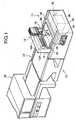
- the nozzle coating equipment 10 in the embodiment of the present invention comprises a coating section 11, a carriage 24 and a drying section 26.
- the coating section 11 is so constructed and operated that, while a coating solution contained in a liquid vessel 18 called “dispenser” is being discharged from a nozzle 20 provided at the lower end of the liquid vessel 18, onto a glass plate 16 for a plasma display panel (abbreviated to "PDP") put on the horizontal support plate 14 of an X - Y robot 12, the liquid vessel 18 is driven in X- and Y-directions along the upper surface of the glass plate 16 by the X - Y robot 12.
- PDP plasma display panel
- the glass plate 16 formed with the coated surface 22 is transported via the carriage 24 to the drying section 26, in which it is dried to complete the coating.
- the liquid vessel 18 is connected with a coating solution tank 28 through a flexible pipe 18A, and is supplied with the coating solution via a controller 30 from the coating solution tank 28.
- the X - Y robot 12 is constructed including the support plate 14 which is free to reciprocate in the Y-direction on an underframe 32, and an X-directional driver 12A which is attached to a gate-shaped frame 13 arranged on the underframe 32 so as to stride over the support plate 14, and which is free to reciprocate in the X-direction while supporting the liquid vessel 18.
- the controller 30, which serves for the movement of the support plate 14 in the Y-direction, the movement of the X-directional driver 12A in the X-direction and the supply of the coating solution, is controlled by a control device 34 which is disposed inside the underframe 32.
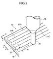
- the lower-end discharge port of the nozzle 20 is arranged in proximity to the upper surface of the glass plate 16, and the gap 36 between the discharge port and the upper surface is set so as to agree with the desired coating film thickness of the coated surface 22 which is formed by the coating with the coating solution.
- control device 34 controls the Y-directional feed of the support plate 14 and the X-directional feed of the X-directional driver 12A as stated below.
- the support plate 14 is driven a predetermined pitch P in the Y-direction on one way of the reciprocation.
- the pitch P is set smaller than the width W of each coating line of the coating solution formed by the nozzle 20.
- one coating line 21 by the nozzle 20 is formed in a manner to overlap another coating line adjoining it in the Y-direction, in the widthwise direction of the coating lines.
- the widthwise pitch P of the coating lines 21 is determined depending upon the diameter of the discharge port of the nozzle 20, the discharge pressure of the coating solution at the discharge port, and the properties of the coating solution including a viscosity and a surface tension.
- the coating solution is endowed with a viscosity of 40,000 [centipoises] by adjusting the quantity of addition of a solvent in a paste which is mainly composed of inorganic powder and a vehicle.
- the gap 36 between the lower end of the nozzle 20 and the upper surface of the glass plate 16 has a value of 230 [ ⁇ m] which is equal to the desired film thickness of the coating film (230 [ ⁇ m] before the drying).
- the tip of the nozzle 20 is in a circular shape which has an inside diameter of 2 [mm] and an outside diameter of 3 [mm].
- the glass plate 16 is of 8-inch size.
- the moving rate of the nozzle 20 is 60 [mm/second] in the X-direction.
- control device 34 is so contrived that, when the support plate 14 is driven one pitch P in the Y-direction after one coating line 21 has been formed owing to the X-directional drive of the nozzle 20, the controller 30 cuts off the exertion of a pressure on the liquid vessel 18 so as to suspend the discharge of the coating solution from the nozzle 20.
- the support plate 14 is driven to the position of the origin in the Y-direction, and the glass plate 16 is set on the support plate 14.
- the liquid vessel 18 (the nozzle 20) is rectilinearly moved in the X-direction by the X-directional driver 12A.
- the first coating line 21A is formed.
- the pressure which is exerted on the liquid vessel 18 is 1 thru 3 [kgf/cm 2 ], and it is held constant during the formation of the coating line.
- the moving rate of the nozzle 20 in the X-direction, the width W of the coating line and the pitch P in the Y-direction are set as mentioned above.
- the discharge of the coating solution from the nozzle 20 is suspended. Therefore, the film thickness of the coated surface 22 is prevented from becoming greater at the terminating end of the coating line 21A than at any other part.
- the support plate 14 is driven one pitch of 1.6 [mm] in the Y-direction.
- the nozzle 20 is driven in the sense opposite to that of the first coating line 21A by the X-directional driver 12A.
- the nozzle 20 thus driven to the initiating end of the second coating line 21B is moved in the X-direction similarly to the above, whereby the second coating line 21B is formed.
- the coated surface 22 having an area of 200 [mm] ⁇ 130 [mm] is deposited on the glass plate 16 of the 8-inch size by way of example.
- the drying of the coated surface 22 in the drying section 26 proceeds as follows by way of example. First, the coated surface 22 is preliminarily dried at 120 [°C] for 20 thru 30 [minutes]. Subsequently, it is finally dried at 170 [°C] for 10 thru 20 [minutes].
- dents 22A having appeared at the widthwise overlap parts between the respectively adjacent ones of the first - third coating lines 21A - 21C are smoothed out as shown in Fig. 3A by way of example.
- the smoothed state is fixed by the final drying which is performed after the preliminary drying.
- the glass plate 16 was coated with the coating solution and was dried under the conditions mentioned above.
- the surface roughness of the coated surface 22 in the example was measured by a surface roughness tester ("Tally-Surf"). Then, the flatness of the coated surface 22 was within 5 [ ⁇ m] relative to the film thickness, 140 [ ⁇ m] of the dried coated surface 22.
- the nozzle 20 in the nozzle coating equipment 10 described above has the discharge port whose cross-section is circular, but the present invention is not restricted to the exemplified nozzle 20.
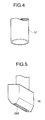
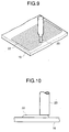
- the nozzle 20 may well be replaced with an elliptical nozzle 37 of elliptical cross-section as shown in Fig. 4, or with a slit-shaped nozzle 38 having a slit-like discharge port 38A as shown in Fig. 5.
- Each of the elliptical nozzle 37 and the slit-shaped nozzle 38 widens the coating line 21, and therefore enhances the rate of the coating operation.
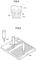
- the component nozzles 40A can be especially arranged as shown in Fig. 7A or Fig. 7B in order that, when the coating solution is discharged from the respective component nozzles 40A, a plurality of coating lines may be formed having a desired magnitude of overlap (for example, 0.4 [mm]).
- the multi-nozzle structure 40 can achieve the same effect as that of the elliptical nozzle 36 or the slit-shaped nozzle 38.
- the single nozzle or the single multi-nozzle structure in the nozzle coating equipment is not restrictive. As shown in Fig. 8, a plurality of nozzles may well be disposed in the Y-direction at regular intervals each of which is integral times the pitch P of the coating lines.
- the Y-directional interval between the n th nozzle 42A precedent in the Y-direction and the succedent (n + 1) th nozzle 42B, and the interval between the (n + 2) th nozzle 42C and the (n + 1) th nozzle 42B are integral times the Y-directional pitch P and are equal as explained above.
- all the nozzles 42A - 42C are driven synchronously or asynchronously in both the X-direction and the Y-direction.
- the drive is controlled by the control device 34 so that the coating line formed first by the n th nozzle 42A and the coating line formed last by the (n + 1) th nozzle 42B may overlap each other in the widthwise direction of the coating lines, similarly to the coating lines shown in Fig. 2 and Figs. 3A and 3B.
- the X - Y robot 12 included in the nozzle coating equipment 10 described before drives the support plate 14 in the Y-direction and drives the liquid vessel 18 in the X-direction through the X-directional driver 12A, whereby the predetermined region of the glass plate 16 is coated with the coating solution by the nozzle 20.
- the present invention is not restricted to the exemplified robot 12. It is also allowed to fix the side of the support plate 14 and to drive the liquid vessel 18 in the X- and Y-directions, or to fix the liquid vessel 18 and to drive the side of the support plate 14 in the X- and Y-directions. Further, both the liquid vessel 18 and the support plate 14 may well be driven in the X- and Y-directions so as to coat the glass plate 16 with the coating solution.
- the gap 36 between the tip of the nozzle 20 and the surface to-be-coated of the glass plate 16 is set equal to the desired film (not dried) thickness of the coated surface 22.
- the present invention is not restricted to the exemplified gap 36.
- the tip of the nozzle 20 may well be spaced more than the desired film thickness from the glass plate 16, so as to form the coating lines by the use of the coating solution which dangles in the shape of a thread from the nozzle 20.
- the spacing between the nozzle 20 and the glass plate 16 may well be set less than the desired film thickness of the coated surface 22 so as to coat the glass plate 16 with the coating solution.
- the surface of the layer of the coating solution discharged onto the glass plate 16 from the tip of the nozzle 20 is stirred in the X-direction. Therefore, the dents 22A between the respectively adjacent coating lines 21 as shown in Fig. 2 and Figs. 3A and 3B are moderated. Accordingly, the surface ruggedness of the coated surface 22 becomes smaller.
- the whole surface of the glass plate 16 for the plasma display panel is formed by so-called “allover coating” with a barrier rib forming layer on the basis of which the barrier rib of the PDP is formed.
- this aspect of the coating operation is not restrictive, but only the predetermined region of the glass plate 16 can be coated with the coating solution by controlling the nozzle 20 and the support plate 14 in the X- and Y-directions by means of the control device 34. That is, the patterning of the coated surface is possible.
- the unnecessary parts of the barrier rib forming layer after the baking thereof may be removed in a smaller area.
- the coating lines can be directly used as the barrier rib in some cases by making the diameter of the hole of the nozzle 20 smaller and enhancing the precisions of the movements in the X- and Y-directions.
- the nozzle 20 is moved along the rectilinear coating lines.
- the present invention is not restricted to the exemplified operation, but it shall also cover a case where a workpiece to-be-coated is coated with the coating solution along coating lines in the shape of a curve such as a circular arc or a spiral by controlling the nozzle 20 and the support plate 14 in the X- and Y-directions by means of the control device 34.
- the present invention is not utilized only for the formation of the barrier rib of the plasma display panel, but it can be utilized also for the formation of thick film patterns in processes for manufacturing a liquid-crystal display device, a phosphorescent display device, a hybrid integrated circuit, etc.
Landscapes
- Chemical & Material Sciences (AREA)
- Life Sciences & Earth Sciences (AREA)
- Engineering & Computer Science (AREA)
- Chemical Kinetics & Catalysis (AREA)
- General Chemical & Material Sciences (AREA)
- Geochemistry & Mineralogy (AREA)
- Materials Engineering (AREA)
- Organic Chemistry (AREA)
- Application Of Or Painting With Fluid Materials (AREA)
- Coating Apparatus (AREA)
- Gas-Filled Discharge Tubes (AREA)
Applications Claiming Priority (3)
| Application Number | Priority Date | Filing Date | Title |
|---|---|---|---|
| JP244436/95 | 1995-09-22 | ||
| JP7244436A JPH0992134A (ja) | 1995-09-22 | 1995-09-22 | ノズル塗布方法及び装置 |
| JP24443695 | 1995-09-22 |
Publications (2)
| Publication Number | Publication Date |
|---|---|
| EP0765694A1 true EP0765694A1 (de) | 1997-04-02 |
| EP0765694B1 EP0765694B1 (de) | 2002-08-28 |
Family
ID=17118630
Family Applications (1)
| Application Number | Title | Priority Date | Filing Date |
|---|---|---|---|
| EP96115179A Expired - Lifetime EP0765694B1 (de) | 1995-09-22 | 1996-09-20 | Verfahren und Anlage zum Düsebeschichten |
Country Status (4)
| Country | Link |
|---|---|
| US (1) | US5776545A (de) |
| EP (1) | EP0765694B1 (de) |
| JP (1) | JPH0992134A (de) |
| DE (1) | DE69623213T2 (de) |
Cited By (5)
| Publication number | Priority date | Publication date | Assignee | Title |
|---|---|---|---|---|
| EP0950438A1 (de) * | 1998-03-19 | 1999-10-20 | Schablonentechnik Kufstein Aktiengesellschaft | Verfahren zum Aufbringen eines Musters auf eine Oberfläche eines Trägers |
| GB2336553A (en) * | 1998-04-24 | 1999-10-27 | Cambridge Display Tech Ltd | Selective deposition of organic films |
| CN103035455A (zh) * | 2010-01-14 | 2013-04-10 | 宜昌劲森照明电子有限公司 | 冷阴极荧光灯电极内涂膜方法 |
| CN103771719A (zh) * | 2014-01-16 | 2014-05-07 | 北京京东方光电科技有限公司 | 一种涂布装置 |
| WO2015200291A3 (en) * | 2014-06-23 | 2016-06-02 | Exel Industries | Methods and apparatus for applying protective films |
Families Citing this family (37)
| Publication number | Priority date | Publication date | Assignee | Title |
|---|---|---|---|---|
| ID21831A (id) * | 1996-12-17 | 1999-07-29 | Toray Industries | Metoda dan peralatan untuk menghasilkan tampilan plasma |
| US6231917B1 (en) | 1998-06-19 | 2001-05-15 | Kabushiki Kaisha Toshiba | Method of forming liquid film |
| US6247986B1 (en) * | 1998-12-23 | 2001-06-19 | 3M Innovative Properties Company | Method for precise molding and alignment of structures on a substrate using a stretchable mold |
| US6352763B1 (en) | 1998-12-23 | 2002-03-05 | 3M Innovative Properties Company | Curable slurry for forming ceramic microstructures on a substrate using a mold |
| JP3697389B2 (ja) | 1999-09-27 | 2005-09-21 | 株式会社東芝 | 液膜形成方法及び塗布膜形成方法 |
| US7125584B2 (en) * | 1999-09-27 | 2006-10-24 | Kabushiki Kaisha Toshiba | Method for forming a liquid film on a substrate |
| US6695922B2 (en) * | 1999-12-15 | 2004-02-24 | Tokyo Electron Limited | Film forming unit |
| US6821178B2 (en) | 2000-06-08 | 2004-11-23 | 3M Innovative Properties Company | Method of producing barrier ribs for plasma display panel substrates |
| JP3366630B2 (ja) * | 2000-10-04 | 2003-01-14 | 大日本スクリーン製造株式会社 | 平面表示装置用の隔壁形成方法及びその装置 |
| JP3425946B2 (ja) * | 2001-09-13 | 2003-07-14 | 大日本スクリーン製造株式会社 | 平面表示装置用の隔壁形成方法及びその装置 |
| US7033534B2 (en) * | 2001-10-09 | 2006-04-25 | 3M Innovative Properties Company | Method for forming microstructures on a substrate using a mold |
| US7176492B2 (en) * | 2001-10-09 | 2007-02-13 | 3M Innovative Properties Company | Method for forming ceramic microstructures on a substrate using a mold and articles formed by the method |
| JP2003187694A (ja) | 2001-12-21 | 2003-07-04 | Dainippon Screen Mfg Co Ltd | 隔壁形成方法、隔壁形成装置およびパネル |
| JP2003187697A (ja) * | 2001-12-21 | 2003-07-04 | Dainippon Screen Mfg Co Ltd | 平面表示装置用の隔壁形成方法及びその装置並びにその方法で製造された背面板 |
| JP2003272523A (ja) * | 2002-01-09 | 2003-09-26 | Dainippon Screen Mfg Co Ltd | 隔壁間塗布方法、隔壁間塗布装置、パターン形成方法、パターン形成装置およびパネル |
| JP2003211045A (ja) * | 2002-01-24 | 2003-07-29 | Three Bond Co Ltd | 材料塗布装置 |
| TWI285563B (en) | 2002-01-24 | 2007-08-21 | Three Bond Co Ltd | Material coating device |
| KR100566840B1 (ko) | 2002-01-30 | 2006-04-03 | 가부시끼가이샤 도시바 | 성막 방법 및 성막 장치 |
| KR100532083B1 (ko) * | 2002-02-20 | 2005-11-30 | 엘지.필립스 엘시디 주식회사 | 일체화된 니들시트를 가진 액정적하장치 |
| JP3957640B2 (ja) * | 2002-02-21 | 2007-08-15 | アイシン化工株式会社 | 幅広スリットノズル及び幅広スリットノズルによる塗装方法 |
| US20040217202A1 (en) * | 2003-04-08 | 2004-11-04 | Hynes Anthony J. | Airless conformal coating apparatus and method |
| JP2004330136A (ja) * | 2003-05-09 | 2004-11-25 | Seiko Epson Corp | 液状膜の乾燥方法、有機elパネルの製造方法、電気光学パネルの製造方法及び電子機器の製造方法、並びに液状膜の乾燥装置、電気光学パネル、電気光学装置及び電子機器 |
| KR100987897B1 (ko) * | 2003-11-25 | 2010-10-13 | 엘지디스플레이 주식회사 | 액정 표시패널의 디스펜서 및 이를 이용한 디스펜싱 방법 |
| KR101025103B1 (ko) * | 2004-03-30 | 2011-03-25 | 엘지디스플레이 주식회사 | 슬릿노즐을 구비하는 포토레지스트 도포장치 |
| JP2006066148A (ja) * | 2004-08-25 | 2006-03-09 | Dainippon Screen Mfg Co Ltd | 平面表示装置用のパネル |
| KR100627361B1 (ko) * | 2004-09-20 | 2006-09-21 | 삼성에스디아이 주식회사 | 플라즈마 디스플레이 패널 및 이의 제조 방법 |
| JP4617875B2 (ja) * | 2004-12-27 | 2011-01-26 | セイコーエプソン株式会社 | 液晶装置の製造方法 |
| JP4980644B2 (ja) * | 2005-05-30 | 2012-07-18 | 東京エレクトロン株式会社 | 塗布方法及び塗布装置 |
| CN100576077C (zh) * | 2005-05-30 | 2009-12-30 | 东京毅力科创株式会社 | 涂布方法和涂布装置 |
| US11136667B2 (en) * | 2007-01-08 | 2021-10-05 | Eastman Kodak Company | Deposition system and method using a delivery head separated from a substrate by gas pressure |
| EP2248597A1 (de) | 2008-02-08 | 2010-11-10 | Central Glass Company, Limited | Vorrichtung und verfahren zum auftragen einer auftragsflüssigkeit |
| JP5317675B2 (ja) * | 2008-12-22 | 2013-10-16 | 株式会社東芝 | 放射線検出器およびその製造方法 |
| DE102010044349A1 (de) * | 2010-09-03 | 2012-04-19 | Fraunhofer-Gesellschaft zur Förderung der angewandten Forschung e.V. | Verfahren und Vorrichtung zur Herstellung einer metallischen Kontaktstruktur zur elektrischen Kontaktierung einer photovoltaischen Solarzelle |
| WO2015060445A1 (ja) | 2013-10-25 | 2015-04-30 | 日本板硝子株式会社 | ガラス板の製造方法及びガラス板 |
| CN107921458B (zh) * | 2015-08-26 | 2021-03-05 | 3M创新有限公司 | 用于形成带有不均一不连续的图案化涂层的制品的方法和设备 |
| EP3341136A4 (de) * | 2015-08-26 | 2019-07-24 | 3M Innovative Properties Company | Verfahren und vorrichtung zur herstellung von artikeln mit ungleichmässig gemusterten beschichtungen |
| CN110620178A (zh) * | 2018-06-19 | 2019-12-27 | 湖北万度光能有限责任公司 | 钙钛矿太阳能电池的制备方法 |
Citations (10)
| Publication number | Priority date | Publication date | Assignee | Title |
|---|---|---|---|---|
| FR2019297A1 (de) * | 1968-07-15 | 1970-07-03 | Feldmuehle Ag | |
| FR2277049A1 (fr) * | 1974-07-02 | 1976-01-30 | Saint Gobain | Appareil pour la realisation d'un film d'oxyde metallique sur une surface de verre |
| US4038442A (en) * | 1975-09-16 | 1977-07-26 | Fuji Photo Film Co., Ltd. | Method for coating |
| DE2704126B1 (de) * | 1977-01-28 | 1978-08-03 | Mannesmann Ag | Verfahren und Vorrichtung zum Erzeugen einer Korrosionsschutzschicht auf Rohren oder anderen langgestreckten Profilen aus Stahl |
| EP0424551A1 (de) * | 1989-10-23 | 1991-05-02 | Karl Reinhard Zeiss | Verfahren zur Herstellung und Verarbeitung von Mehrkomponenten-Mischungen auf Basis von Reaktionskunststoffen |
| GB2245508A (en) * | 1990-06-28 | 1992-01-08 | Nec Corp | Spray type flux applying device |
| EP0622476A1 (de) * | 1993-03-30 | 1994-11-02 | Alusuisse-Lonza Services Ag | Metallsubstrate mit laserinduzierter MMC-Beschichtung |
| EP0636467A2 (de) * | 1993-07-30 | 1995-02-01 | Bayer Ag | Verfahren und Vorrichtung zum Beschichten eines um eine Achse rotierenden Körpers |
| GB2280391A (en) * | 1993-07-31 | 1995-02-01 | Valpar Ind Ltd | Coating pipes, cables or hoses |
| US5455063A (en) * | 1991-11-26 | 1995-10-03 | Goldstar Co., Ltd. | Method for forming conductive film |
Family Cites Families (3)
| Publication number | Priority date | Publication date | Assignee | Title |
|---|---|---|---|---|
| KR910003693B1 (en) * | 1988-09-14 | 1991-06-08 | Samsung Electronic Devices | Pdp barrack manufacturing method |
| KR910003690B1 (en) * | 1988-09-14 | 1991-06-08 | Samsung Electronic Devices | Pdp manufacturing method |
| US5348585A (en) * | 1993-01-07 | 1994-09-20 | Weston Colin K | Liquid dispensing apparatus |
-
1995
- 1995-09-22 JP JP7244436A patent/JPH0992134A/ja active Pending
-
1996
- 1996-09-20 EP EP96115179A patent/EP0765694B1/de not_active Expired - Lifetime
- 1996-09-20 DE DE69623213T patent/DE69623213T2/de not_active Expired - Fee Related
- 1996-09-20 US US08/717,348 patent/US5776545A/en not_active Expired - Fee Related
Patent Citations (10)
| Publication number | Priority date | Publication date | Assignee | Title |
|---|---|---|---|---|
| FR2019297A1 (de) * | 1968-07-15 | 1970-07-03 | Feldmuehle Ag | |
| FR2277049A1 (fr) * | 1974-07-02 | 1976-01-30 | Saint Gobain | Appareil pour la realisation d'un film d'oxyde metallique sur une surface de verre |
| US4038442A (en) * | 1975-09-16 | 1977-07-26 | Fuji Photo Film Co., Ltd. | Method for coating |
| DE2704126B1 (de) * | 1977-01-28 | 1978-08-03 | Mannesmann Ag | Verfahren und Vorrichtung zum Erzeugen einer Korrosionsschutzschicht auf Rohren oder anderen langgestreckten Profilen aus Stahl |
| EP0424551A1 (de) * | 1989-10-23 | 1991-05-02 | Karl Reinhard Zeiss | Verfahren zur Herstellung und Verarbeitung von Mehrkomponenten-Mischungen auf Basis von Reaktionskunststoffen |
| GB2245508A (en) * | 1990-06-28 | 1992-01-08 | Nec Corp | Spray type flux applying device |
| US5455063A (en) * | 1991-11-26 | 1995-10-03 | Goldstar Co., Ltd. | Method for forming conductive film |
| EP0622476A1 (de) * | 1993-03-30 | 1994-11-02 | Alusuisse-Lonza Services Ag | Metallsubstrate mit laserinduzierter MMC-Beschichtung |
| EP0636467A2 (de) * | 1993-07-30 | 1995-02-01 | Bayer Ag | Verfahren und Vorrichtung zum Beschichten eines um eine Achse rotierenden Körpers |
| GB2280391A (en) * | 1993-07-31 | 1995-02-01 | Valpar Ind Ltd | Coating pipes, cables or hoses |
Cited By (8)
| Publication number | Priority date | Publication date | Assignee | Title |
|---|---|---|---|---|
| EP0950438A1 (de) * | 1998-03-19 | 1999-10-20 | Schablonentechnik Kufstein Aktiengesellschaft | Verfahren zum Aufbringen eines Musters auf eine Oberfläche eines Trägers |
| US6083571A (en) * | 1998-03-19 | 2000-07-04 | Schablonentechnik Kufstein Aktiengesellschaft | Method of applying a pattern to a surface of a substrate |
| GB2336553A (en) * | 1998-04-24 | 1999-10-27 | Cambridge Display Tech Ltd | Selective deposition of organic films |
| GB2336553B (en) * | 1998-04-24 | 2003-01-08 | Cambridge Display Tech Ltd | Manufacture of optic, electronic or optoelectronic devices |
| CN103035455A (zh) * | 2010-01-14 | 2013-04-10 | 宜昌劲森照明电子有限公司 | 冷阴极荧光灯电极内涂膜方法 |
| CN103771719A (zh) * | 2014-01-16 | 2014-05-07 | 北京京东方光电科技有限公司 | 一种涂布装置 |
| CN103771719B (zh) * | 2014-01-16 | 2015-09-09 | 北京京东方光电科技有限公司 | 一种涂布装置 |
| WO2015200291A3 (en) * | 2014-06-23 | 2016-06-02 | Exel Industries | Methods and apparatus for applying protective films |
Also Published As
| Publication number | Publication date |
|---|---|
| EP0765694B1 (de) | 2002-08-28 |
| DE69623213D1 (de) | 2002-10-02 |
| DE69623213T2 (de) | 2002-12-19 |
| JPH0992134A (ja) | 1997-04-04 |
| US5776545A (en) | 1998-07-07 |
Similar Documents
| Publication | Publication Date | Title |
|---|---|---|
| US5776545A (en) | Nozzle coating method and equipment | |
| US5921836A (en) | Apparatus for forming fluorescent layers of a plasma display panel and method therefor | |
| KR100578617B1 (ko) | 액정적하장치 및 방법 및 액정표시패널 제조장치 | |
| KR100683688B1 (ko) | 유전체층 형성 장치 및 이를 이용한 플라즈마 디스플레이패널의 제조 방법 | |
| JP4059305B2 (ja) | スクリーン印刷装置 | |
| CN1922016A (zh) | 用于模板擦拭器组件的自持式真空模块 | |
| JP2002086044A (ja) | 塗布方法および塗布装置並びにディスプレイ用部材およびプラズマディスプレイの製造方法およびその製造装置 | |
| KR100336300B1 (ko) | 플라즈마디스플레이패널의형광체층형성방법과장치및이에사용되는필라멘트형상성형체와그성형체의제조방법 | |
| JPH11239750A (ja) | 凹凸基材への塗液の塗布装置および方法並びにプラズマディスプレイの製造装置および方法 | |
| JP4324998B2 (ja) | 塗布装置および塗布方法並びにプラズマディスプレイの製造方法および製造装置 | |
| JP2012192332A (ja) | 塗布装置、塗布方法およびディスプレイ用部材の製造方法 | |
| CN1198247A (zh) | 用丝网印刷法或模板印刷法在基板上供给彩色单元 | |
| JP2000102759A (ja) | 塗布方法および塗布装置並びにプラズマディスプレイおよびディスプレイ用部材の製造方法および製造装置 | |
| JP2004141707A (ja) | 塗布方法及び塗布装置ならびにプラズマディスプレイ用部材の製造方法 | |
| JP2002140982A (ja) | プラズマディスプレイ用発光基板の製造装置および製造方法 | |
| US7037161B2 (en) | Method of manufacturing flat panel displays utilizing a surface treating layer | |
| JP2001000904A (ja) | 塗布装置および方法並びにプラズマディスプレイおよびディスプレイ用部材の製造装置および方法 | |
| JP3994357B2 (ja) | 凹凸基材への塗液の塗布装置および方法並びにプラズマディスプレイの製造装置および方法 | |
| JP2000354810A (ja) | 塗布装置および方法並びにプラズマディスプレイおよびディスプレイ用部材の製造装置および方法 | |
| JP3885838B2 (ja) | プラズマディスプレイパネルの蛍光体層形成方法および装置 | |
| JPH11239748A (ja) | 凹凸基材への塗液の塗布装置および方法並びにプラズマディスプレイの製造装置および方法 | |
| JP3676351B2 (ja) | プラズマディスプレイパネルの蛍光体層形成装置および蛍光体層の形成方法 | |
| KR100578958B1 (ko) | 플라즈마 디스플레이 패널의 격벽 제조용 페이스트 도포장치 | |
| JP2001076619A (ja) | プラズマディスプレイパネルの蛍光体層形成装置とその形成方法 | |
| JP2008080188A (ja) | 塗布方法および塗布装置並びにディスプレイ用部材の製造方法 |
Legal Events
| Date | Code | Title | Description |
|---|---|---|---|
| PUAI | Public reference made under article 153(3) epc to a published international application that has entered the european phase |
Free format text: ORIGINAL CODE: 0009012 |
|
| AK | Designated contracting states |
Kind code of ref document: A1 Designated state(s): DE FR GB |
|
| 17P | Request for examination filed |
Effective date: 19970813 |
|
| 17Q | First examination report despatched |
Effective date: 19990426 |
|
| GRAG | Despatch of communication of intention to grant |
Free format text: ORIGINAL CODE: EPIDOS AGRA |
|
| GRAG | Despatch of communication of intention to grant |
Free format text: ORIGINAL CODE: EPIDOS AGRA |
|
| GRAH | Despatch of communication of intention to grant a patent |
Free format text: ORIGINAL CODE: EPIDOS IGRA |
|
| GRAH | Despatch of communication of intention to grant a patent |
Free format text: ORIGINAL CODE: EPIDOS IGRA |
|
| GRAA | (expected) grant |
Free format text: ORIGINAL CODE: 0009210 |
|
| AK | Designated contracting states |
Kind code of ref document: B1 Designated state(s): DE FR GB |
|
| REG | Reference to a national code |
Ref country code: GB Ref legal event code: FG4D |
|
| RIN1 | Information on inventor provided before grant (corrected) |
Inventor name: SHIOZAKI, KAZUYUKI, C/O DAI NIPPON PRINTING CO,LT Inventor name: WATANABE, KAZUO, C/O DAI NIPPON PRINTING CO., LTD Inventor name: OHASHI, YOICHIRO, C/O DAI NIPPON PRINTING CO., LT Inventor name: YOSHIBA, HIROSHI, C/O DAI NIPPON PRINTING CO., LTD |
|
| REF | Corresponds to: |
Ref document number: 69623213 Country of ref document: DE Date of ref document: 20021002 |
|
| ET | Fr: translation filed | ||
| PLBE | No opposition filed within time limit |
Free format text: ORIGINAL CODE: 0009261 |
|
| STAA | Information on the status of an ep patent application or granted ep patent |
Free format text: STATUS: NO OPPOSITION FILED WITHIN TIME LIMIT |
|
| 26N | No opposition filed |
Effective date: 20030530 |
|
| PGFP | Annual fee paid to national office [announced via postgrant information from national office to epo] |
Ref country code: DE Payment date: 20070907 Year of fee payment: 12 |
|
| PGFP | Annual fee paid to national office [announced via postgrant information from national office to epo] |
Ref country code: GB Payment date: 20070823 Year of fee payment: 12 |
|
| PGFP | Annual fee paid to national office [announced via postgrant information from national office to epo] |
Ref country code: FR Payment date: 20070821 Year of fee payment: 12 |
|
| GBPC | Gb: european patent ceased through non-payment of renewal fee |
Effective date: 20080920 |
|
| REG | Reference to a national code |
Ref country code: FR Ref legal event code: ST Effective date: 20090529 |
|
| PG25 | Lapsed in a contracting state [announced via postgrant information from national office to epo] |
Ref country code: DE Free format text: LAPSE BECAUSE OF NON-PAYMENT OF DUE FEES Effective date: 20090401 |
|
| PG25 | Lapsed in a contracting state [announced via postgrant information from national office to epo] |
Ref country code: FR Free format text: LAPSE BECAUSE OF NON-PAYMENT OF DUE FEES Effective date: 20080930 |
|
| PG25 | Lapsed in a contracting state [announced via postgrant information from national office to epo] |
Ref country code: GB Free format text: LAPSE BECAUSE OF NON-PAYMENT OF DUE FEES Effective date: 20080920 |