EP0636719B1 - Dispositif de frisage par fausse torsion - Google Patents
Dispositif de frisage par fausse torsion Download PDFInfo
- Publication number
- EP0636719B1 EP0636719B1 EP94111627A EP94111627A EP0636719B1 EP 0636719 B1 EP0636719 B1 EP 0636719B1 EP 94111627 A EP94111627 A EP 94111627A EP 94111627 A EP94111627 A EP 94111627A EP 0636719 B1 EP0636719 B1 EP 0636719B1
- Authority
- EP
- European Patent Office
- Prior art keywords
- bracket
- compression spring
- holding device
- spring
- hand
- Prior art date
- Legal status (The legal status is an assumption and is not a legal conclusion. Google has not performed a legal analysis and makes no representation as to the accuracy of the status listed.)
- Expired - Lifetime
Links
- 238000002788 crimping Methods 0.000 title description 2
- 230000006835 compression Effects 0.000 claims description 18
- 238000007906 compression Methods 0.000 claims description 18
- 238000003780 insertion Methods 0.000 description 2
- 230000037431 insertion Effects 0.000 description 2
- 238000000034 method Methods 0.000 description 2
- 230000001154 acute effect Effects 0.000 description 1
- 238000013459 approach Methods 0.000 description 1
- 238000006073 displacement reaction Methods 0.000 description 1
- 230000013011 mating Effects 0.000 description 1
Images


Classifications
-
- D—TEXTILES; PAPER
- D02—YARNS; MECHANICAL FINISHING OF YARNS OR ROPES; WARPING OR BEAMING
- D02G—CRIMPING OR CURLING FIBRES, FILAMENTS, THREADS, OR YARNS; YARNS OR THREADS
- D02G1/00—Producing crimped or curled fibres, filaments, yarns, or threads, giving them latent characteristics
- D02G1/02—Producing crimped or curled fibres, filaments, yarns, or threads, giving them latent characteristics by twisting, fixing the twist and backtwisting, i.e. by imparting false twist
- D02G1/04—Devices for imparting false twist
- D02G1/08—Rollers or other friction causing elements
- D02G1/082—Rollers or other friction causing elements with the periphery of at least one disc
Definitions
- the invention relates to a false twist crimping device according to the preamble of claim 1.
- Such devices are known (DE-A-2 612 023). They consist of detachably connected upper and lower parts.
- the upper part has three spindles equipped with friction disks.
- One of these spindles is provided at its lower end with a pulley and a whorl which rests against an endless drive belt.
- the other two spindles also each carry a pulley and are driven by the whirl-driven spindle via a common belt.
- the whorl can be moved to another spindle and to the other side of the drive belt, so that its direction of rotation and thus the direction of twist are reversed.
- the lower part serves as a support for the upper part and for fastening the device to a texturing machine.
- the lower part has an opening through which the whorl protrudes.
- a pressure roller with its axis parallel to the axis of the whorl. It is carried by an adjustable holder and can be switched to the opposite side of the drive belt depending on the position of the whorl.
- the drive belt runs between the whorl and the pressure roller in full contact on their lateral surfaces.
- a device on the lower part that resiliently clamps the pressure roller and the whorl against each other. Since the False twisting process of synthetic yarns with such devices is generally known, a detailed description is unnecessary.
- the invention has for its object to provide a false twisting device which, in addition to the switchability between and S to Z twist, can be functionally attached to a texturing machine in practically any orientation, in particular also offers the possibility of shifting forces caused by a the inclined orientation of the device on the machine deviating from the normal working position can be caused to compensate or compensate.
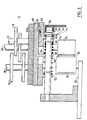
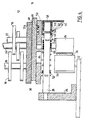
- the false twisting device 10 shown in the figures, below also called an aggregate, consists of an upper part 12 and a lower part 14.
- a detachable connection, not shown here, between the two parts usually consists of a screw connection and mating alignment nozzles and bores.
- three spindles 18, 20, 22, shown broken and each equipped with a plurality of friction disks 16, are rotatably arranged, the bearings of which satisfy modern high-speed texturing processes.
- the bearings (not shown) are so far apart in a fastening 12a at the tips of an arrangement in the form of an isosceles triangle that partial regions of the friction disks 16 pointing into the interior of the triangle overlap. This overlap area is used in a known manner for twisting the threads of a thread.
- the spindles 18, 20, 22 are provided at their end in the lower part 14 of the assembly 10 with pulleys, not shown, which are connected to one another by a drive belt. At this end of one of the spindles there is also a whorl 24, which can optionally be moved to one of the other two spindles.
- the lower part 14 of the device 10 consists of a holder 26, which is used to attach the device 10 to the frame of the texturing machine, not shown. From the upper end of the holder 26, rod-shaped arms 28 protrude at right angles, only one of which is visible and which carry a carriage 30 connected to the upper part 12 of the device 10.
- An adjustable support arm 32 is provided on the end of the holder 26 opposite the arms 28, and a pressure roller 34 is provided on the free end thereof is mounted, the outer surface of which is parallel to the outer surface of the whorl 24 when the upper part 12 is attached.
- the pressure roller 34 can be switched from the position shown in FIGS. 1 and 3 to the position shown in FIGS. 2 and 4 when the whorl 24 is repositioned accordingly, so that it lies either on one or the other side of a drive belt 36.
- the drive belt 36 runs along the front of the machine and between the whorl 24 and the pressure roller 34, which clamp the belt 36 between them. Since the whorl 24 can be moved from one spindle to another and the pressure roller 34 can also be adjusted via the support arm 32, they can be placed against one or the other belt surface, whereby the direction of rotation is reversed for the purpose of swirl reversal.
- two grooves 38, 40 are provided at a distance from one another, which are used to hold bolts or the like.
- a radial bore 42 in the boom At its free end there is a radial bore 42 in the boom.
- a sift 44 In the bore 42 there is a sift 44 which is secured against falling out of the bore 42.
- the pin 44 can be adjusted so that either one or its other end projects beyond the lateral surface of the arm 28.
- a compression spring 46 is placed on the arm 28.
- the carriage 30 consists of two superimposed plates 48, 50 which are provided with openings which are aligned with one another and through which the whorl 24 protrudes into the lower part 14 of the assembly 10. From the lower plate 50 of the carriage 30, two pierced lugs 52, 54 project downwards, which are stuck on the arm 28 and between which the compression spring 46 lies.
- the compression spring 46 is longer than the distance between a shoulder 52, 54 and the groove 38, 40 remote from it.
- the pin 44 lies on the end of the arm 28 protruding from the shoulder 54.
- a sleeve 58 provided with an arm 56 arm, the outer surface of which is broken by two opposing link guides 60, 62, each of which has a cam surface intersecting the axis of the arm 28 at an acute angle, against which the end of the pin 44 projecting from the outer surface of the arm 28 rests.
- the sleeve 58 is rotatably connected to the outer shoulder 54 in a manner not shown.
- the upper plate 48 of the carriage 30 is adjustable with respect to the lower plate 50 in the direction of the extension arm 28 and has a projection 66 which projects through the opening 64 and which is fixedly connected to the compression spring 46 in the center thereof.
- the upper plate 48 serves as the actual support for the upper part 12 of the unit 10.
- an interlocking toothing 68 is provided, which, for the purposes described below, adjusts the two plates towards each other in the direction of the boom 28 allows.
- the respective position of the plates is secured to each other by a screw connection, not shown.
- the toothing 68 is shown as a tooth protruding from the upper plate 48, which falls into one of three grooves in the lower plate 50. The middle of these three grooves then forms the normal setting of the plates 48, 50 to one another. If necessary, more than three grooves can be provided, which would result in a finer adjustability of the plates relative to one another.
- the compression spring 46 on one side of the shoulder 66 can be subjected to a greater load than on the other side.
- the upper plate 48 is moved to the left with respect to the lower plate 50 along the toothing.
- Fig. 3 the device 10 is shown in an orientation which leads to twisting in the opposite direction of rotation with the same direction of travel of the drive belt 36.
- the position of the whorl 24 and the pressure roller 34 with respect to the drive belt 36 is reversed from that shown in FIG. 1. That is, the pressure roller 34 is on the left and the whorl 24 is on the right of the belt 36.
- the reversed position of the whorl 24 and the pressure roller 34 results in the need to reverse the pretension of the carriage 30 generated by the spring 46.
- an additional one-sided loading of the compression spring 46 can counteract a shift in force that occurs as a result.
- the upper plate 48 of the slide 30 is adjusted to the right against the lower 50, so that the distance between the shoulder 66, which is fixedly connected to the spring 46, and the bolt 40a is reduced, and thus the compression of the Spring 46 would be increased in this area. Accordingly, the spring 46 is relieved in the area between the lugs 66 and 52. Subsequent rotation of the sleeve 58, while the spring 46 is tensioned, causes the slide 30 to be shifted to the right on the bracket 28 over its entire length.
- the described force compensation for right and left-inclined alignments of the unit is independent of the direction of swirl or the position of whorl 24 and pressure roller 34 on the drive belt 36. That is, in any case, the end of the compression spring 46 pointing in the direction of the inclination would be as above described in addition to tension.
- the arm 56 on the sleeve 58 is preferably designed such that it prevents the insertion of a thread between the friction disks 16 of the device 10 when the compression spring 46 is relaxed, when the assembly 10 is at rest, by lying transversely in front of the insertion slot and after the tensioning of the spring 46 when the Rotate friction discs 16 due to the abutment of the whorl 24 on the drive belt 36 without being able to be guided between them.
Landscapes
- Engineering & Computer Science (AREA)
- Mechanical Engineering (AREA)
- Textile Engineering (AREA)
- Yarns And Mechanical Finishing Of Yarns Or Ropes (AREA)
Claims (8)
- Dispositif (10) pour imprimer une fausse torsion à un fil synthétique dans une machine à texturer à trois ou quatre arbres parallèles (18, 20, 22) qui sont montés sur un moyen de support (30) dans les points d'angle d'un polygone équilatéral et entraînés en rotation et dans le même sens par un galet (24) et sur chacun desquels plusieurs disques de friction (16) sont montés en rotation et se chevauchent au-dessus du centre du polygone, le galet pouvant, pour réaliser sélectivement une torsion dans le sens S ou Z, être appliqué selon le sens de torsion contre l'une ou l'autre face d'une courroie d'entraînement (36) défilant dans un sens prédéfini, caractérisé en ce que a) le moyen de support (30) est monté avec une possibilité de translation par rapport au bâti (26) de la machine ; b) pour appliquer le galet (24) contre la courroie d'entraînement (36), il est prévu un ressort de pression (46) prenant appui, d'une part, sur le bâti (26) de la machine et, d'autre part, sur le moyen de support (30) ; c) un moyen de liaison réglable (66) est prévu entre le moyen de support (30) et le ressort de pression (46) pour faire varier sélectivement la force élastique.
- Dispositif selon la revendication 1, caractérisé en ce que le moyen de support (30) est un chariot monté coulissant sur un bras (28) faisant saillie du bâti (26) de la machine.
- Dispositif selon la revendication 2, caractérisé en ce que le chariot (30) se compose de deux plaques (48, 50) pouvant se déplacer l'une par rapport à l'autre dans le sens du bras (28) et dont l'une (12a, 48) porte les broches (18, 20, 22) et l'autre (50) est portée par le bras (28).
- Dispositif selon la revendication 3, caractérisé en ce que le chariot (30) est relié au bras (28) par deux pattes distantes l'une de l'autre (52, 54), et en ce qu'il est prévu sur le bras (28), pour assurer la coopération avec l'une des pattes (52, 54), des dispositifs activables alternativement (38, 38a, 40, 40a) pour fournir un appui au ressort de pression (46).
- Dispositif selon la revendication 4, caractérisé en ce qu'à l'extrémité libre du bras (28) sont prévus des dispositifs pour tendre le ressort de pression (46) entre un bras (52, 54) et le dispositif d'appui activé (38, 38a ; 40, 40a).
- Dispositif selon la revendication 5, caracterisé en ce que les dispositifs pour tendre le ressort de pression (46) sont des guides à coulisse (60, 62) activables alternativement avec des saillies courbes en sens inverse au force de ressort, qui sont conjuguées aux dispositifs d'appui.
- Dispositif selon la revendication 6, caractérisé en ce que les guides à coulisse (60, 62) sont actionnés par un axe (44) mobile transversalement au bras (28).
- Dispositif selon la revendication 7, caractérisé en ce que le moyen de liaison destiné à régler la force élastique est une patte (66) solidarisée, d'une part, à la plaque (48) portant les broches (18, 20, 22) et, d'autre part, au ressort de pression (46) au centre de celui-ci.
Applications Claiming Priority (2)
| Application Number | Priority Date | Filing Date | Title |
|---|---|---|---|
| DE4325633 | 1993-07-30 | ||
| DE4325633 | 1993-07-30 |
Publications (2)
| Publication Number | Publication Date |
|---|---|
| EP0636719A1 EP0636719A1 (fr) | 1995-02-01 |
| EP0636719B1 true EP0636719B1 (fr) | 1997-10-22 |
Family
ID=6494096
Family Applications (1)
| Application Number | Title | Priority Date | Filing Date |
|---|---|---|---|
| EP94111627A Expired - Lifetime EP0636719B1 (fr) | 1993-07-30 | 1994-07-26 | Dispositif de frisage par fausse torsion |
Country Status (3)
| Country | Link |
|---|---|
| EP (1) | EP0636719B1 (fr) |
| DE (1) | DE59404399D1 (fr) |
| ES (1) | ES2108913T3 (fr) |
Families Citing this family (3)
| Publication number | Priority date | Publication date | Assignee | Title |
|---|---|---|---|---|
| DE102009015026A1 (de) | 2009-03-26 | 2010-09-30 | Oerlikon Textile Components Gmbh | Falschdrallaggregat |
| CN118373254B (zh) * | 2024-06-21 | 2024-10-18 | 山东明福绿色纤维有限公司 | 一种纺织加工用纺线合股卷绕设备 |
| CN120138853B (zh) * | 2025-04-16 | 2025-10-10 | 绍兴华裕纺机有限公司 | 一种加弹组件、加弹机及加弹控制方法 |
Family Cites Families (3)
| Publication number | Priority date | Publication date | Assignee | Title |
|---|---|---|---|---|
| DE2612023C3 (de) * | 1976-03-20 | 1982-04-01 | Barmag Barmer Maschinenfabrik Ag, 5630 Remscheid | Falschdrallvorrichtung |
| FR2484472A1 (fr) * | 1980-06-14 | 1981-12-18 | Barmag Barmer Maschf | Dispositif de fausse torsion a friction pour la texturation par fausse torsion de fils synthetiques et son procede de fonctionnement |
| DE4110464A1 (de) * | 1991-03-30 | 1992-10-01 | Kugelfischer G Schaefer & Co | Friktionsfalschdrallaggregat mit elektromotorischem antrieb |
-
1994
- 1994-07-26 DE DE59404399T patent/DE59404399D1/de not_active Expired - Fee Related
- 1994-07-26 EP EP94111627A patent/EP0636719B1/fr not_active Expired - Lifetime
- 1994-07-26 ES ES94111627T patent/ES2108913T3/es not_active Expired - Lifetime
Also Published As
| Publication number | Publication date |
|---|---|
| EP0636719A1 (fr) | 1995-02-01 |
| DE59404399D1 (de) | 1997-11-27 |
| ES2108913T3 (es) | 1998-01-01 |
Similar Documents
| Publication | Publication Date | Title |
|---|---|---|
| DE102010019284B4 (de) | Riementrieb zur Umsetzung einer Drehbewegung in eine Linearbewegung | |
| DE2612023A1 (de) | Friktionsaggregat mit zwei antriebswirteln | |
| EP0636719B1 (fr) | Dispositif de frisage par fausse torsion | |
| DE1948718U (de) | Spannklammer fuer spannketten von rahmenspannern. | |
| DE60102742T2 (de) | Halter zum Positionieren von Einheiten die Textilfasern strecken und verdichten | |
| EP1900474A2 (fr) | Dispositif de traitement de bâtons | |
| CH663173A5 (de) | Vorrichtung zum schnelleinspannen von skiern verschiedener breite. | |
| EP0777773B1 (fr) | Dispositif a lames | |
| DE3123753C2 (fr) | ||
| DE2209827A1 (de) | Vorrichtung zum Spulen eines Garnwickels | |
| DE2249263B1 (de) | Falschdraht-aggregat | |
| DE3215700A1 (de) | Handhabungseinrichtung, insbesondere zum bestuecken, entladen und transportieren von werkstuecken | |
| DE4130968C2 (de) | Vorrichtung zur Aufnahme eines Falschdrallaggregates in Form eines beweglichen Supportes | |
| DE29508369U1 (de) | Stickrahmen mit einer Spannvorrichtung | |
| EP0535198B1 (fr) | Dispositif de serrage pour une couche de fils plane et utilisation dudit dispositif | |
| DE1192779B (de) | Falschdrahtvorrichtung zum Kraeuseln von synthetischen thermoplastischen Faeden | |
| DE19740498A1 (de) | Werkzeuggreifer für einen Speicherplatz eines Kettenmagazines an einer Werkzeugmaschine | |
| DE3505439A1 (de) | Rahmenspannvorrichtung | |
| DE3021121C2 (de) | Vorrichtung zum Auflegen und Spannen eines Endlosriemens einer Spinn- und Zwirnmaschine | |
| DE4120498C2 (de) | Einfädelvorrichtung für ein Fixzenterfriktionsaggregat | |
| DE69206676T2 (de) | Vorrichtung zum Fertigbearbeiten einer Konusähnlichen Oberfläche | |
| DE10034432B4 (de) | Weiche zum Sortieren und Führen von Teilen | |
| DE4447017C1 (de) | Zahnriemenspanneinrichtung | |
| CH636138A5 (en) | False-twisting device on a texturing machine for textile threads | |
| DE2541542A1 (de) | Antriebssystem zum gemeinsamen antrieb von in reihe angeordneten wellen |
Legal Events
| Date | Code | Title | Description |
|---|---|---|---|
| PUAI | Public reference made under article 153(3) epc to a published international application that has entered the european phase |
Free format text: ORIGINAL CODE: 0009012 |
|
| AK | Designated contracting states |
Kind code of ref document: A1 Designated state(s): CH DE ES FR GB IT LI |
|
| 17P | Request for examination filed |
Effective date: 19950307 |
|
| GRAG | Despatch of communication of intention to grant |
Free format text: ORIGINAL CODE: EPIDOS AGRA |
|
| 17Q | First examination report despatched |
Effective date: 19961014 |
|
| GRAH | Despatch of communication of intention to grant a patent |
Free format text: ORIGINAL CODE: EPIDOS IGRA |
|
| GRAH | Despatch of communication of intention to grant a patent |
Free format text: ORIGINAL CODE: EPIDOS IGRA |
|
| GRAA | (expected) grant |
Free format text: ORIGINAL CODE: 0009210 |
|
| AK | Designated contracting states |
Kind code of ref document: B1 Designated state(s): CH DE ES FR GB IT LI |
|
| REG | Reference to a national code |
Ref country code: CH Ref legal event code: EP |
|
| ITF | It: translation for a ep patent filed | ||
| REF | Corresponds to: |
Ref document number: 59404399 Country of ref document: DE Date of ref document: 19971127 |
|
| REG | Reference to a national code |
Ref country code: CH Ref legal event code: NV Representative=s name: BARMAG GMBH ENGINEERING & MANUFACTURING |
|
| REG | Reference to a national code |
Ref country code: ES Ref legal event code: FG2A Ref document number: 2108913 Country of ref document: ES Kind code of ref document: T3 |
|
| GBT | Gb: translation of ep patent filed (gb section 77(6)(a)/1977) |
Effective date: 19971219 |
|
| ET | Fr: translation filed | ||
| PLBE | No opposition filed within time limit |
Free format text: ORIGINAL CODE: 0009261 |
|
| STAA | Information on the status of an ep patent application or granted ep patent |
Free format text: STATUS: NO OPPOSITION FILED WITHIN TIME LIMIT |
|
| 26N | No opposition filed | ||
| PGFP | Annual fee paid to national office [announced via postgrant information from national office to epo] |
Ref country code: GB Payment date: 20010704 Year of fee payment: 8 |
|
| PGFP | Annual fee paid to national office [announced via postgrant information from national office to epo] |
Ref country code: FR Payment date: 20010717 Year of fee payment: 8 |
|
| PGFP | Annual fee paid to national office [announced via postgrant information from national office to epo] |
Ref country code: CH Payment date: 20010723 Year of fee payment: 8 |
|
| PGFP | Annual fee paid to national office [announced via postgrant information from national office to epo] |
Ref country code: ES Payment date: 20010730 Year of fee payment: 8 |
|
| PGFP | Annual fee paid to national office [announced via postgrant information from national office to epo] |
Ref country code: DE Payment date: 20010928 Year of fee payment: 8 |
|
| REG | Reference to a national code |
Ref country code: GB Ref legal event code: IF02 |
|
| PG25 | Lapsed in a contracting state [announced via postgrant information from national office to epo] |
Ref country code: GB Free format text: LAPSE BECAUSE OF NON-PAYMENT OF DUE FEES Effective date: 20020726 |
|
| PG25 | Lapsed in a contracting state [announced via postgrant information from national office to epo] |
Ref country code: ES Free format text: LAPSE BECAUSE OF NON-PAYMENT OF DUE FEES Effective date: 20020727 |
|
| PG25 | Lapsed in a contracting state [announced via postgrant information from national office to epo] |
Ref country code: LI Free format text: LAPSE BECAUSE OF NON-PAYMENT OF DUE FEES Effective date: 20020731 Ref country code: CH Free format text: LAPSE BECAUSE OF NON-PAYMENT OF DUE FEES Effective date: 20020731 |
|
| PG25 | Lapsed in a contracting state [announced via postgrant information from national office to epo] |
Ref country code: DE Free format text: LAPSE BECAUSE OF NON-PAYMENT OF DUE FEES Effective date: 20030201 |
|
| REG | Reference to a national code |
Ref country code: CH Ref legal event code: PL |
|
| GBPC | Gb: european patent ceased through non-payment of renewal fee |
Effective date: 20020726 |
|
| PG25 | Lapsed in a contracting state [announced via postgrant information from national office to epo] |
Ref country code: FR Free format text: LAPSE BECAUSE OF NON-PAYMENT OF DUE FEES Effective date: 20030331 |
|
| REG | Reference to a national code |
Ref country code: FR Ref legal event code: ST |
|
| REG | Reference to a national code |
Ref country code: ES Ref legal event code: FD2A Effective date: 20030811 |
|
| PG25 | Lapsed in a contracting state [announced via postgrant information from national office to epo] |
Ref country code: IT Free format text: LAPSE BECAUSE OF NON-PAYMENT OF DUE FEES;WARNING: LAPSES OF ITALIAN PATENTS WITH EFFECTIVE DATE BEFORE 2007 MAY HAVE OCCURRED AT ANY TIME BEFORE 2007. THE CORRECT EFFECTIVE DATE MAY BE DIFFERENT FROM THE ONE RECORDED. Effective date: 20050726 |