EP1900474A2 - Dispositif de traitement de bâtons - Google Patents
Dispositif de traitement de bâtons Download PDFInfo
- Publication number
- EP1900474A2 EP1900474A2 EP07016892A EP07016892A EP1900474A2 EP 1900474 A2 EP1900474 A2 EP 1900474A2 EP 07016892 A EP07016892 A EP 07016892A EP 07016892 A EP07016892 A EP 07016892A EP 1900474 A2 EP1900474 A2 EP 1900474A2
- Authority
- EP
- European Patent Office
- Prior art keywords
- profile bar
- screw unit
- screw
- unit
- profile
- Prior art date
- Legal status (The legal status is an assumption and is not a legal conclusion. Google has not performed a legal analysis and makes no representation as to the accuracy of the status listed.)
- Granted
Links
Images


Classifications
-
- B—PERFORMING OPERATIONS; TRANSPORTING
- B23—MACHINE TOOLS; METAL-WORKING NOT OTHERWISE PROVIDED FOR
- B23P—METAL-WORKING NOT OTHERWISE PROVIDED FOR; COMBINED OPERATIONS; UNIVERSAL MACHINE TOOLS
- B23P19/00—Machines for simply fitting together or separating metal parts or objects, or metal and non-metal parts, whether or not involving some deformation; Tools or devices therefor so far as not provided for in other classes
- B23P19/04—Machines for simply fitting together or separating metal parts or objects, or metal and non-metal parts, whether or not involving some deformation; Tools or devices therefor so far as not provided for in other classes for assembling or disassembling parts
- B23P19/06—Screw or nut setting or loosening machines
Definitions
- the invention relates to a profile bar processing device with a screw unit, in particular for screwing reinforcements on profile bars, wherein the screw unit has at least one feeding device and a screwing device for screws.
- Profile bar processing devices with a screw unit for example for screwing reinforcements to profile bars
- These screwdrivers have a working head with which the screws are screwed.
- the known screwdriver units are connected to a feeder, for example a vibrator or a magazine, from where screws are fed from the working head.
- These screwdriver units are arranged in a so-called machining center, in which a plurality of machining operations on a profile bar are carried out successively.
- machining center in which a plurality of machining operations on a profile bar are carried out successively.
- the object of the invention is to provide a profile bar processing device with a screw unit, with the simple way in two opposite sides of a profile bar screws can be introduced and which is inexpensive to carry out.
- a profile bar processing device is provided with a screw unit, in particular for screwing reinforcements on profile bars, wherein the screw unit has at least one feeding device and a screwing device, wherein a screw unit of the screw unit starting from a first, substantially perpendicular to a longitudinal axis of a machining profile bar arranged position is arranged pivotably about a predefined angle, in particular 180 ° in a second, also arranged substantially perpendicular to the profile bar to be machined position.
- the screwdriver unit can in particular be designed such that the screwing unit can be pivoted about the profiled bar without the profiled bar having to be removed from the swiveling area of the screwing unit. Since it is possible to dispense with a second screw unit, creating a simple and thus cheaper construction. For round or polygonal profiles, pivoting around angles deviating from 180 ° may be useful.
- a reinforcement can be screwed from the top and one inside by means of swiveling by 90 °.
- a pivot axis about which the screw unit is pivoted, can be perpendicular to a profile longitudinal axis or parallel thereto.
- a very significant advantage of the invention is also that by the spatial separation of screw and machining unit, for example, for milling, by Vorverlagern of the screw with respect to the material flow, the reinforcements can be screwed in a first profile and at the same time a second profile can be milled ,
- the screwdriver unit has, in addition to the feeding device and the screwing device, a drive by means of which the screwing device for screwing in the screws is set in rotation.
- This drive can be designed in different ways, for example electrically or pneumatically.
- a receptacle for so-called bits is provided on the screw unit, wherein the bits are adapted to the screw heads of the screws used.
- the receptacle is in particular designed so that the bits are exchangeable.
- the screws to be screwed are fed to the screwing device.
- the feeder can a kind of magazine, in which a certain number of screws is received aligned.
- the magazine may be, for example, a paper strip, a housing or the like.
- the feeder may also be a so-called vibrator, are filled into the screws disorderly. By means of shaking movement and arranged in the vibrator guiding and sorting the screws are then aligned the same.
- the aligned screws are then fed, for example, by means of a hose or the like of Einfilvorraum.
- the use of a vibrator creates a virtually endless screw feeding possibility.
- a linear displacement device can be provided in the profile rod machining device with which a profile rod to be machined can be displaced in a direction parallel to its central longitudinal axis.
- This linear displacement device is advantageous because in this way the profile bar to be machined can be guided along the screw unit so that the screw unit can screw screws into the profile bar at different positions along the profile bar without having to be arranged to be linearly displaceable.
- the linear displaceability of the screwdriver unit can be considered as an alternative to the linear displaceability of the profile bar.
- the screwdriver unit is arranged on a first profile bar processing position and the further processing units are arranged on at least a second, spatially separated from the first profile bar processing position profile bar processing position of the profile bar.
- the first and the second profile bar processing position are provided in particular in a common profile bar processing device, made with the various processing steps on the profile bar can be.
- the throughput of a profile bar processing device can be increased. This is because processing steps such as drilling and / or milling can be done simultaneously with the Verschraubvorgang.
- It is also advantageous that by separating the processing positions of the screw unit is sufficient time available to pivot from the first to the second processing position. This is because the processing steps of the second profiled-bar processing position, for example during drilling and milling, typically take a total longer than the screwing in the first profiled-bar processing position.
- a pivot axis is arranged perpendicular to the longitudinal axis of a profile bar to be machined and lying in a region of a center plane of the profile bar to be machined.
- the screw unit can be designed for this purpose so that the pivot axis, for example by means of various linear actuators, can be converted into the corresponding positions.
- a reference is provided for the screw, which is independent of the screw unit and depends only on the profile bar being processed. The reproducibility of a screwing is thereby significantly increased or their accessibility significantly simplified.
- the screw is rotatably connected to a gear which meshes with a displaceably arranged rack.
- a pneumatic cylinder is provided for moving the rack.
- stops for defining the first and the second position of the screw unit are provided, wherein at least one hydraulic shock absorber interacts with the stops.
- the at least one hydraulic shock absorber acts in this arrangement as a buffer, so that a quick pivoting movement of the screw can be slowed down gently and any vibrations of the profile bar processing device will not be given to the screw unit on.
- the hydraulic shock absorber may also be provided a pneumatic shock absorber or for example a spring arrangement or the like.
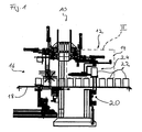
- FIG. 1 shows a profile bar processing device 10 with a first processing unit 12, which is designed as a screw unit 14 according to the invention, and with a second processing unit 16, in the example not shown drilling, milling, sawing and / or grinding devices or may be provided.
- the profile bar processing device 10 also has a material transport path 18 with a lifting device 20 for positioning the profile bars 22 in an engagement region 24 of the screw unit 14.
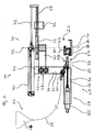
- the side view of the screwdriver unit 14 shown in FIG. 2 in a first processing position shows a feed unit 26, a screwing unit 28 and a pivoting device 30 for pivoting the screwing unit 28 about a pivot axis 32.
- the screw unit 28 has a stepped angled support 34 which is connected to a first arm 36 with a driving device 38 and a second arm 40 with a gear 42, wherein the first arm 36 and the second arm 40 have in opposite directions.
- a central portion 44 of the carrier 34 are in a region 46, which faces the arm 40, arranged in Fig.2 with each other two identically formed hydraulic shock absorbers 48, wherein the central longitudinal axes the hydraulic shock absorbers 48 are arranged aligned perpendicular to a plane defined by the carrier 34 and the directions of action of the hydraulic shock absorbers 48 are opposite to each other.
- the driving device 38 has a drive 50 which is connected to an axis 52, with which a so-called bit 54 is engaged.
- the bit 54 is formed corresponding to a screw head of a screw to be screwed and is guided in a sleeve 56 with a Y-piece 58.
- the sleeve 56 forms with the Y-piece 58 and a transfer line 60 a screw positioning device 62, are positioned with the same aligned, but not shown self-tapping screws before the bit 54, in Fig.2 so right of the bit 54.
- the fferenpositionier -Vorraum 62 communicates by means of the transfer line 60 with a feed unit 26, which is designed as a so-called vibrator 64 with a supply line 66 which is connected to the transfer line 60.
- the pivoting device 30, which is fixed in rotation and fixed to the profile bar processing device, not shown in Figure 2, has a rack 68 which meshes with the gear 42 and which is connected to a piston rod 72 of a pneumatic cylinder 70.
- stops 74 are still attached to each of which, depending on the pivoting of the screw 28, one of the hydraulic shock absorber 48 is applied.
- the screwdriver unit 14 is used to insert screws into profile bars 22, which are for this purpose lying on a receptacle 76, which is in engagement with the lifting device 20 of Figure 1, lifted by means of the lifting device in an engagement region 24 of the screw unit 14.
- the receptacle 76 is arranged so that the pivot axis 32 lies on a median plane 84 of the receptacle 76.
- Parallel to, but not necessarily congruent with the median plane 84 of the receptacle 76 extends a median plane 86 of the profile bar 22, wherein on the median plane 86 of the profile bar 22 is a central longitudinal axis 88 of the profile bar 22.
- the central longitudinal axis 86 of the profile bar 22 is perpendicular to the viewing plane of Fig.2.
- the screwing unit 28 of the screwdriver unit 14 of FIG. 2 is pivoted in the illustration according to FIG. 4 by 180 ° about the pivot axis 32.
- the piston rod 72 of the pneumatic cylinder 70 is retracted so that the rack 68, the gear 42 and thus the screw 28 is set in a rotational movement.
- a profile bar 22 on two opposite sides 82 to be provided with screws, not shown, for example, to screw 22 in the profile bar, not shown reinforcements.
- the hydraulic shock absorber 48 are provided, which cooperate with the stops 74 depending on the orientation of the screw 28. Since the hydraulic shock absorbers 48 are arranged at the middle part 44 of the carrier 34 with each other, the stops 74 are of different lengths.
Landscapes
- Engineering & Computer Science (AREA)
- Mechanical Engineering (AREA)
- Turning (AREA)
- Multi-Process Working Machines And Systems (AREA)
- Electrical Discharge Machining, Electrochemical Machining, And Combined Machining (AREA)
- Lead Frames For Integrated Circuits (AREA)
- Transmission Devices (AREA)
- Reinforcement Elements For Buildings (AREA)
Applications Claiming Priority (1)
| Application Number | Priority Date | Filing Date | Title |
|---|---|---|---|
| DE102006045845.1A DE102006045845B4 (de) | 2006-09-15 | 2006-09-15 | Profilstabbearbeitungs-Vorrichtung |
Publications (3)
| Publication Number | Publication Date |
|---|---|
| EP1900474A2 true EP1900474A2 (fr) | 2008-03-19 |
| EP1900474A3 EP1900474A3 (fr) | 2008-07-23 |
| EP1900474B1 EP1900474B1 (fr) | 2010-12-08 |
Family
ID=38819337
Family Applications (1)
| Application Number | Title | Priority Date | Filing Date |
|---|---|---|---|
| EP07016892A Active EP1900474B1 (fr) | 2006-09-15 | 2007-08-29 | Dispositif de traitement de bâtons |
Country Status (3)
| Country | Link |
|---|---|
| EP (1) | EP1900474B1 (fr) |
| AT (1) | ATE490842T1 (fr) |
| DE (2) | DE102006045845B4 (fr) |
Cited By (5)
| Publication number | Priority date | Publication date | Assignee | Title |
|---|---|---|---|---|
| CN104162770A (zh) * | 2014-08-22 | 2014-11-26 | 辽宁省机械研究院有限公司 | 空调换热器芯体割片拧钉用自动系统装置及其使用方法 |
| CN110216465A (zh) * | 2019-05-10 | 2019-09-10 | 广东德帆科技有限公司 | 一种型材螺丝快速拉铆机 |
| CN114589658A (zh) * | 2022-04-01 | 2022-06-07 | 山东建筑大学 | 一种建筑构件拆除装置 |
| CN117798651A (zh) * | 2024-02-18 | 2024-04-02 | 格力电器(郑州)有限公司 | 一种锁紧装置及应用其的空调组装流水线 |
| IT202300023079A1 (it) * | 2023-11-02 | 2025-05-02 | Emmegi Spa | Apparato e metodo per lavorare barre profilate |
Citations (2)
| Publication number | Priority date | Publication date | Assignee | Title |
|---|---|---|---|---|
| JPS5976732A (ja) | 1982-10-22 | 1984-05-01 | Nissan Motor Co Ltd | 自動ねじ締め機 |
| DE10301237A1 (de) | 2002-01-15 | 2003-07-24 | Denso Corp | Robotervorrichtung mit einer Roboterhand für Hochlastarbeit |
Family Cites Families (7)
| Publication number | Priority date | Publication date | Assignee | Title |
|---|---|---|---|---|
| IL47265A (en) * | 1975-05-09 | 1978-08-31 | Tadiran Israel Elect Ind Ltd | Inserts installing machine |
| US4569116A (en) * | 1984-03-12 | 1986-02-11 | Enterkin Manufacturing Co., Inc. | Automatic stud driving machine with pilot hole pre-drilling capability |
| DD245154A1 (de) * | 1985-12-24 | 1987-04-29 | Fortschritt Veb K | Werkzeugsystem |
| DD247400A1 (de) * | 1986-03-31 | 1987-07-08 | Werkzeugmasch Forschzent | Einrichtung zum montieren und demontieren von schraubelementen |
| DE3825144A1 (de) * | 1988-07-23 | 1990-01-25 | Fenstertechnik Gmbh | Vorrichtung zum transportieren und bearbeiten von profilstangen |
| DE19623451A1 (de) * | 1996-06-12 | 1997-12-18 | Rapid Maschbau Gmbh | Vorrichtung zum Verschrauben von Hohlkammerprofilen |
| DE29918907U1 (de) * | 1999-10-27 | 2000-02-03 | Alu Technic Ludwig Gutmann GmbH, 91792 Ellingen | Vorrichtung zum Verankern von Hohlprofilquersprossen an Hohlprofillängsholmen |
-
2006
- 2006-09-15 DE DE102006045845.1A patent/DE102006045845B4/de active Active
-
2007
- 2007-08-29 EP EP07016892A patent/EP1900474B1/fr active Active
- 2007-08-29 AT AT07016892T patent/ATE490842T1/de active
- 2007-08-29 DE DE502007005886T patent/DE502007005886D1/de active Active
Patent Citations (2)
| Publication number | Priority date | Publication date | Assignee | Title |
|---|---|---|---|---|
| JPS5976732A (ja) | 1982-10-22 | 1984-05-01 | Nissan Motor Co Ltd | 自動ねじ締め機 |
| DE10301237A1 (de) | 2002-01-15 | 2003-07-24 | Denso Corp | Robotervorrichtung mit einer Roboterhand für Hochlastarbeit |
Cited By (7)
| Publication number | Priority date | Publication date | Assignee | Title |
|---|---|---|---|---|
| CN104162770A (zh) * | 2014-08-22 | 2014-11-26 | 辽宁省机械研究院有限公司 | 空调换热器芯体割片拧钉用自动系统装置及其使用方法 |
| CN110216465A (zh) * | 2019-05-10 | 2019-09-10 | 广东德帆科技有限公司 | 一种型材螺丝快速拉铆机 |
| CN114589658A (zh) * | 2022-04-01 | 2022-06-07 | 山东建筑大学 | 一种建筑构件拆除装置 |
| CN114589658B (zh) * | 2022-04-01 | 2023-04-25 | 山东建筑大学 | 一种建筑构件拆除装置 |
| IT202300023079A1 (it) * | 2023-11-02 | 2025-05-02 | Emmegi Spa | Apparato e metodo per lavorare barre profilate |
| EP4549084A1 (fr) * | 2023-11-02 | 2025-05-07 | Emmegi S.P.A. | Apparail et méthode d'usinage de barres profilees |
| CN117798651A (zh) * | 2024-02-18 | 2024-04-02 | 格力电器(郑州)有限公司 | 一种锁紧装置及应用其的空调组装流水线 |
Also Published As
| Publication number | Publication date |
|---|---|
| EP1900474A3 (fr) | 2008-07-23 |
| DE502007005886D1 (de) | 2011-01-20 |
| DE102006045845A1 (de) | 2008-03-27 |
| EP1900474B1 (fr) | 2010-12-08 |
| ATE490842T1 (de) | 2010-12-15 |
| DE102006045845B4 (de) | 2014-11-20 |
Similar Documents
| Publication | Publication Date | Title |
|---|---|---|
| DE102007027808B3 (de) | Spannvorrichtung | |
| EP1900474B1 (fr) | Dispositif de traitement de bâtons | |
| DE102011017425B9 (de) | Spannvorrichtung zum Spannen von Werkstücken | |
| DE3233102C1 (de) | Vorrichtung zur lösbaren Verbindung von Greiferschienenteilen der Greiferschienen in einer Transfer-Presse | |
| EP3542962A1 (fr) | Système de support lors du serrage d'une pièce à usiner | |
| DE4443512A1 (de) | Bearbeitungsmaschine für gerade und gekrümmte Werkstücke, insbesondere aus Holz | |
| DE8706196U1 (de) | Winkelschraubstock | |
| DE10311392A1 (de) | Biegemaschine, insbesondere für Schweiß- und Spanntische, sowie Schweiß- und Spanntisch | |
| DE60223987T2 (de) | Stanzmaschine | |
| DE3419187C2 (fr) | ||
| DE10137887A1 (de) | Spannvorrichtung | |
| EP2769816A1 (fr) | Module de fraisage | |
| DE10025077A1 (de) | Spannzwinge | |
| DE10241863B3 (de) | Spanneinrichtung für prismatische Werkstücke | |
| DE2543547C2 (de) | Werkstückspannvorrichtung an einer Gewindeschneidmaschine | |
| EP0636719B1 (fr) | Dispositif de frisage par fausse torsion | |
| EP1704939B1 (fr) | Dispositif d'alimentation de fils, en particulier vers machines de soudage | |
| DE19818254C1 (de) | Teilapparat | |
| DE3420558A1 (de) | Bohrmaschine | |
| DE10227984B4 (de) | Führungsvorrichtung zum geführten Bewegen einer Handwerkzeugmaschine in einer Vorschubrichtung | |
| DE2549705A1 (de) | Schlauchmontage-vorrichtung | |
| DE102022102852A1 (de) | Automationskomponente, insbesondere Greif- oder Spannvorrichtung, mit einer translatorisch und rotatorisch verfahrbaren Grundbacke, Backenaufbau und Automationssystem | |
| DE102006045847B3 (de) | Profilbearbeitungs-Vorrichtung und Verfahren zum Bearbeiten von Profilstäben | |
| DE10259871B4 (de) | Handbetätigte Bearbeitungsvorrichtung unter Verwendung eines Parallelschraubstocks | |
| CH707380B1 (de) | Spanneinrichtung für ein oder mehrere Werkstücke für eine Bearbeitung derselben. |
Legal Events
| Date | Code | Title | Description |
|---|---|---|---|
| PUAI | Public reference made under article 153(3) epc to a published international application that has entered the european phase |
Free format text: ORIGINAL CODE: 0009012 |
|
| AK | Designated contracting states |
Kind code of ref document: A2 Designated state(s): AT BE BG CH CY CZ DE DK EE ES FI FR GB GR HU IE IS IT LI LT LU LV MC MT NL PL PT RO SE SI SK TR |
|
| AX | Request for extension of the european patent |
Extension state: AL BA HR MK YU |
|
| PUAL | Search report despatched |
Free format text: ORIGINAL CODE: 0009013 |
|
| AK | Designated contracting states |
Kind code of ref document: A3 Designated state(s): AT BE BG CH CY CZ DE DK EE ES FI FR GB GR HU IE IS IT LI LT LU LV MC MT NL PL PT RO SE SI SK TR |
|
| AX | Request for extension of the european patent |
Extension state: AL BA HR MK RS |
|
| 17P | Request for examination filed |
Effective date: 20080827 |
|
| 17Q | First examination report despatched |
Effective date: 20081010 |
|
| AKX | Designation fees paid |
Designated state(s): AT DE FR GB IT TR |
|
| RAP1 | Party data changed (applicant data changed or rights of an application transferred) |
Owner name: ELUMATEC GMBH |
|
| GRAJ | Information related to disapproval of communication of intention to grant by the applicant or resumption of examination proceedings by the epo deleted |
Free format text: ORIGINAL CODE: EPIDOSDIGR1 |
|
| GRAP | Despatch of communication of intention to grant a patent |
Free format text: ORIGINAL CODE: EPIDOSNIGR1 |
|
| GRAP | Despatch of communication of intention to grant a patent |
Free format text: ORIGINAL CODE: EPIDOSNIGR1 |
|
| GRAS | Grant fee paid |
Free format text: ORIGINAL CODE: EPIDOSNIGR3 |
|
| GRAA | (expected) grant |
Free format text: ORIGINAL CODE: 0009210 |
|
| AK | Designated contracting states |
Kind code of ref document: B1 Designated state(s): AT DE FR GB IT TR |
|
| REG | Reference to a national code |
Ref country code: GB Ref legal event code: FG4D Free format text: NOT ENGLISH |
|
| REF | Corresponds to: |
Ref document number: 502007005886 Country of ref document: DE Date of ref document: 20110120 Kind code of ref document: P |
|
| PLBE | No opposition filed within time limit |
Free format text: ORIGINAL CODE: 0009261 |
|
| STAA | Information on the status of an ep patent application or granted ep patent |
Free format text: STATUS: NO OPPOSITION FILED WITHIN TIME LIMIT |
|
| 26N | No opposition filed |
Effective date: 20110909 |
|
| REG | Reference to a national code |
Ref country code: DE Ref legal event code: R097 Ref document number: 502007005886 Country of ref document: DE Effective date: 20110909 |
|
| REG | Reference to a national code |
Ref country code: FR Ref legal event code: PLFP Year of fee payment: 10 |
|
| REG | Reference to a national code |
Ref country code: FR Ref legal event code: PLFP Year of fee payment: 11 |
|
| REG | Reference to a national code |
Ref country code: FR Ref legal event code: PLFP Year of fee payment: 12 |
|
| REG | Reference to a national code |
Ref country code: DE Ref legal event code: R082 Ref document number: 502007005886 Country of ref document: DE Representative=s name: PATENTANWAELTE RUFF, WILHELM, BEIER, DAUSTER &, DE Ref country code: DE Ref legal event code: R081 Ref document number: 502007005886 Country of ref document: DE Owner name: ELUMATEC AG, DE Free format text: FORMER OWNER: ELUMATEC GMBH, 75417 MUEHLACKER, DE |
|
| PGFP | Annual fee paid to national office [announced via postgrant information from national office to epo] |
Ref country code: AT Payment date: 20220818 Year of fee payment: 16 |
|
| P01 | Opt-out of the competence of the unified patent court (upc) registered |
Effective date: 20230525 |
|
| REG | Reference to a national code |
Ref country code: AT Ref legal event code: MM01 Ref document number: 490842 Country of ref document: AT Kind code of ref document: T Effective date: 20230829 |
|
| PG25 | Lapsed in a contracting state [announced via postgrant information from national office to epo] |
Ref country code: AT Free format text: LAPSE BECAUSE OF NON-PAYMENT OF DUE FEES Effective date: 20230829 |
|
| PG25 | Lapsed in a contracting state [announced via postgrant information from national office to epo] |
Ref country code: AT Free format text: LAPSE BECAUSE OF NON-PAYMENT OF DUE FEES Effective date: 20230829 |
|
| PGFP | Annual fee paid to national office [announced via postgrant information from national office to epo] |
Ref country code: DE Payment date: 20250819 Year of fee payment: 19 |
|
| PGFP | Annual fee paid to national office [announced via postgrant information from national office to epo] |
Ref country code: TR Payment date: 20250821 Year of fee payment: 19 Ref country code: IT Payment date: 20250829 Year of fee payment: 19 |
|
| PGFP | Annual fee paid to national office [announced via postgrant information from national office to epo] |
Ref country code: GB Payment date: 20250822 Year of fee payment: 19 |
|
| PGFP | Annual fee paid to national office [announced via postgrant information from national office to epo] |
Ref country code: FR Payment date: 20250821 Year of fee payment: 19 |