EP0636748B1 - Procédé pour sécuriser les surplombs en danger de glissement et pour la stabilisation de surplombs en sols cohérents, sols à cohérence expansible et sols à structure granulaire fine, lesquels peuvent présenter conjointement des particules grossières - Google Patents
Procédé pour sécuriser les surplombs en danger de glissement et pour la stabilisation de surplombs en sols cohérents, sols à cohérence expansible et sols à structure granulaire fine, lesquels peuvent présenter conjointement des particules grossières Download PDFInfo
- Publication number
- EP0636748B1 EP0636748B1 EP94111629A EP94111629A EP0636748B1 EP 0636748 B1 EP0636748 B1 EP 0636748B1 EP 94111629 A EP94111629 A EP 94111629A EP 94111629 A EP94111629 A EP 94111629A EP 0636748 B1 EP0636748 B1 EP 0636748B1
- Authority
- EP
- European Patent Office
- Prior art keywords
- landslides
- risk
- slope
- stabilising
- landslide
- Prior art date
- Legal status (The legal status is an assumption and is not a legal conclusion. Google has not performed a legal analysis and makes no representation as to the accuracy of the status listed.)
- Expired - Lifetime
Links
Images




Classifications
-
- E—FIXED CONSTRUCTIONS
- E02—HYDRAULIC ENGINEERING; FOUNDATIONS; SOIL SHIFTING
- E02D—FOUNDATIONS; EXCAVATIONS; EMBANKMENTS; UNDERGROUND OR UNDERWATER STRUCTURES
- E02D3/00—Improving or preserving soil or rock, e.g. preserving permafrost soil
- E02D3/12—Consolidating by placing solidifying or pore-filling substances in the soil
-
- E—FIXED CONSTRUCTIONS
- E02—HYDRAULIC ENGINEERING; FOUNDATIONS; SOIL SHIFTING
- E02D—FOUNDATIONS; EXCAVATIONS; EMBANKMENTS; UNDERGROUND OR UNDERWATER STRUCTURES
- E02D17/00—Excavations; Bordering of excavations; Making embankments
- E02D17/20—Securing of slopes or inclines
-
- Y—GENERAL TAGGING OF NEW TECHNOLOGICAL DEVELOPMENTS; GENERAL TAGGING OF CROSS-SECTIONAL TECHNOLOGIES SPANNING OVER SEVERAL SECTIONS OF THE IPC; TECHNICAL SUBJECTS COVERED BY FORMER USPC CROSS-REFERENCE ART COLLECTIONS [XRACs] AND DIGESTS
- Y02—TECHNOLOGIES OR APPLICATIONS FOR MITIGATION OR ADAPTATION AGAINST CLIMATE CHANGE
- Y02A—TECHNOLOGIES FOR ADAPTATION TO CLIMATE CHANGE
- Y02A10/00—TECHNOLOGIES FOR ADAPTATION TO CLIMATE CHANGE at coastal zones; at river basins
- Y02A10/23—Dune restoration or creation; Cliff stabilisation
Definitions
- the invention relates to a method for securing slopes at risk of slipping and restoring landslides in the case of cohesive, cohesive to generally fine-grained soils, in which a minor coarse fraction may be present.
- Landslides or slides occur from everything in clayey, clayey-silty and clayey-marbled rock sequences. This can cause major economic damage to roads, railways and inhabited areas. It is often necessary to secure slopes that are at risk of slipping, so that structures and structures underneath or on top of them Traffic routes or the like, are not endangered.
- the sliding surface should first be drained so that the slide is brought to a standstill or at least slowed down.
- horizontal tunnels are excavated using the mining method below the endangered slope or the slide or horizontal pressures.
- anchors and bored pile walls are inserted vertically downwards or diagonally into solid rock layers through the slide slope. For this, very heavy vehicles have to be driven onto the sliding slope, which further increases the risk of the slope creeping or sliding. The vibrations generated when the anchors and bored pile walls are inserted also increase the risk of the slope slipping.
- a method is also known in which bores are drilled vertically downwards through the sliding slope into solid rock and solidifications are achieved by cement injections into the surrounding soil area. A large number of such cement injections significantly improve the stability of the soil and the Slide stopped.
- this known method has the disadvantage that heavy vehicles have to be driven onto the slope, which is at risk of slipping.
- the above-mentioned methods can therefore not be used on all slope glides or landslides, since it is often not possible to drive onto the slide slope without endangering equipment and personnel.
- the technical problem on which the invention is based is to secure or rehabilitate a slope that is at risk of slipping or a slip slope without risk for operating personnel and equipment, safely, quickly and inexpensively against further slipping, so that under certain circumstances the further use of buildings that are already at risk is ensured .
- the solution to this technical problem is a method for securing slopes that are at risk of slipping and for cleaning up landslides on cohesive, swellable cohesive to generally fine-grained soils, in which a minor coarse fraction can be present, such as clays, silt, marl, Lithuanian, or Schlier the like, to create at least one completely course-controlled bore from below or above or to the side of the slide slope from at least one point outside the area of the slope or the slide which is at risk of slipping is driven forward and the completely course-controlled bore is then advanced at the desired point through the sliding surface of the slide into the slide slope and suitable injection means are injected from the bore to solidify the surrounding floor area.
- a minor coarse fraction can be present, such as clays, silt, marl, Lithuanian, or Schlier the like
- the invention is based on the idea of completely avoiding the previously necessary loads or vibrations on slopes or landslides that are already at risk of slipping, so that there is no increase in the risk of slipping. Furthermore, it is to be achieved that at any point in the slide slope there are injections for anchoring the slide slope to the surrounding mountains and this without providing expensive equipment and operating personnel.
- the anchoring of the slide slope with the underlying mountains can be optimally achieved by drilling the holes, which are preferably introduced deep into the fixed mountains from locations below the slide and then remote controlled, depending on the ground conditions, through the sliding surface essentially vertically upwards into the Slides are driven forward. Through such bores, a very deep anchoring of the slide slope with the surrounding mountains can be achieved.
- suitable injection means are injected in the essentially vertical drilling sections to solidify the surrounding bottom area of the drilling, as a result of which a non-positive connection is formed between the slide slope and the surrounding mountains.
- the bore depending on local conditions can be driven from anywhere outside the slide. This ensures that the device and personnel are not additionally endangered. Furthermore, the holes drilled underneath or to the side of the sliding slope mean that a wide variety of drilling patterns are possible and, depending on the conditions, existing structures and safety devices can also be integrated or, if necessary, driven under.
- the method according to the invention thus also offers the possibility of anchoring in the slide slope there, which are not accessible from the outside, that is to say from the surface.
- the method according to the invention when the bore is made in and through the sliding surface, runs along the water between the drill wall and the drill head or the drill string, through which the bore, which runs at least with a slight inclination, can flow down below the slide slope. Because of this, drainage of the slide slope is advantageously ensured already during drilling, whereby the risk of the slope slipping is already considerably reduced.
- a multiplicity of bores can be driven from one or more locations outside the slide slope and introduced into the slide slope, as a result of which arbitrary distributions of ground anchors by injection are conceivable.
- radial injections can be made in the surrounding bottom area of a borehole, which, in cooperation with the sliding direction of the slope, form transom structures and provide good protection against further movement of the sliding slope. Injections distributed in the form of disks or rolls in the surrounding bottom area of a bore are also possible.
- a particularly advantageous distribution of the bores with a minimal change of device status is achieved when a plurality of bores below the slide slope are driven from two locations outside the slide slope and run essentially vertically through the sliding surface up to the surface of the slide slope and then the bottom areas of the essentially vertical drill sections are injected with injection agent.
- Optimal parcelling of the slide slope is achieved in the method according to the invention in that holes are made from a plurality of points below the slide slope at least in pairs at acute angles to one another, essentially parallel to the slide direction, in the slide slope.
- the boreholes driven from the neighboring locations are essentially parallel to one another and then injection means are introduced into the ground in suitable borehole sections.
- Such crossbars are advantageously introduced in the upper region of the slide slope in the vicinity of the slide break, so that further slipping of the slope is prevented.
- the bores can be introduced into the slide slope below the slide slope in such a way that the calculated maximum sliding circle is also pierced. This ensures the best possible securing of the sliding slope.
- Another formation of a new sliding surface, which by the computationally determined slip circles can be included by the method according to the invention and further slippage can be prevented as best as possible.
- Cement-based binders are particularly advantageous as injection means, but other injection means suitable for consolidating the soil are also possible.
- the following injection agents can be used in the process according to the invention: ultrafine cements, waxes, resins, water glass solutions / silicate gels, polymer silicates, phenoplasts, aminoplasts, lignosulfides, lignosulfonates, acrylamines, foams, bitumen and fillers such as stone powder, slag, ash, sand or the like.
- FIG. 1a shows a cross section through a slide slope 1 which has a sliding surface 3 and a slide tear 2 in the upper region. Furthermore, a calculated sliding circle 7 is drawn with a dash-dotted line, which represents the maximum sliding surface of the sliding slope 1. From a point 5 below the slide slope, various bores 6 in a first section run slightly ascending through the surrounding mountains 10. In a second section, the bores run with increasing steepness through the sliding circle 7 and the sliding surface 3 up to the surface of the slide slope 1. In these steep, essentially vertical sections of the bores 6, injection areas are shown schematically, which non-positively connect the slide slope 1 to the pending mountains 10. In order to drive these different bores 6, a drilling device 5 is raised below the slide slope. With the drilling device 5, different holes can be driven from one point into or through the sliding slope and injection means can be injected into the surrounding bottom areas of the holes 6 in various ways when the drilling head is withdrawn.
- the cross section through the slide slope 1 shown in FIG. 1 b corresponds to that from FIG. 1 a, but with this procedure the injection areas of the individual bores 6 overlap.
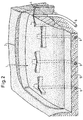
- FIG. 2 One possibility of the various forms of injecting injection agent into the surrounding bottom areas of a bore 6 is shown in FIG. 2.
- a cut or covered slide 1 is shown schematically with the slide 2.
- Different holes 6 extend into the slide slope 1 and each have injection areas 4 radiating from the bore 6, which extend essentially transversely to the direction of sliding of the slope.
- the injection areas 4 form an effective cross bar, which extends over the entire slide slope 1 and extends deep into the surrounding mountains 10.
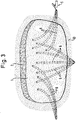
- Fig. 3 is again schematically shown a slide 1 with a slide 2, in each of which a number of holes 6 run into the slide 1 from different locations lying on the side or below the slide 1. All the holes 6 penetrate the sliding surface of the slide slope 1 from below and run steeply into the slide slope 1. The injection areas are not shown here, but in all holes in the steep areas injection agent is injected into the surrounding bottom areas of the respective hole 6.
- the distribution of the bores shown is very efficient, since the drilling device 5 can drive a wide variety of bores 6 from one location.
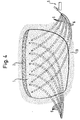
- FIG. 4 schematically shows a distribution of the holes 6 extending into the slide slope 1.
- no drilling device 5 has to be raised below the sliding slope, which can possibly be a very high risk for the device and the operating personnel.
- the network-shaped distribution of the bores 6 in the plan view here results in a very uniform distribution of the injection regions, not shown, which extend from the surface of the slide slope deep into the mountains. This ensures an efficient, inexpensive but also very good securing of the sliding slope.
- FIG. 5 A further exemplary distribution of the bores 6 according to the method according to the invention is shown in FIG. 5.
- at least two bores 6 each run from a point below the sliding slope 1 essentially parallel to the sliding direction of the slope into the sliding slope 1.
- the bores 6 starting from one point form an acute angle.
- a number of such bores 6 which run at an acute angle to one another are essentially parallel to one another in the plan view.
- a division of the slide slope 1 into individual segments is achieved, as a result of which, in the region of the steeper drill sections, the drill sections in the slide slope reaching into the surrounding mountains 10 are again treated with injection agent. A good connection between slide slope 1 and fixed mountain 10 is thereby achieved.
- FIG. 6 Another embodiment is shown in FIG. 6.
- the transverse bores 6 begin on the side of the slide slope 1, run through the peaks 10 in the slide slope 1 and bump into the peaks 10 on the opposite side of the slide slope 1.
- the injection agent is then in the surrounding bottom areas of the respective holes 6 a length is injected so that a cross bar extending from the surrounding mountains 10 through the slide slope 1 to the surrounding mountains 10 is formed.
- Crossbars optimally secure the upper area, possibly also in the lower-lying slide slope area.
- the lateral arrangement of the drilling device 5 avoids endangering operating personnel and the device even if the sliding slope 1 slips further.
- 7a and 7b show further exemplary injection areas in the floor.
- 7a shows that a helical injection area 4 is formed in the vicinity of the bore 6 by the rotation and a movement along the bore axis of the bore 6.
- Such a formation of the injected floor areas represents an optimal frictional connection in the slide slope.
- FIG. 7b A roller-shaped configuration of the injected floor areas is shown schematically in FIG. 7b.
- Such a distribution in which the entire floor area was injected with injection agent in a predetermined radius around the bore 6, also represents the optimal non-positive connection between the slide slope and the surrounding mountains for certain floors.
Landscapes
- Engineering & Computer Science (AREA)
- Mining & Mineral Resources (AREA)
- Life Sciences & Earth Sciences (AREA)
- Structural Engineering (AREA)
- General Engineering & Computer Science (AREA)
- Civil Engineering (AREA)
- Paleontology (AREA)
- General Life Sciences & Earth Sciences (AREA)
- Agronomy & Crop Science (AREA)
- Environmental & Geological Engineering (AREA)
- Soil Sciences (AREA)
- Pit Excavations, Shoring, Fill Or Stabilisation Of Slopes (AREA)
- Tires In General (AREA)
Claims (20)
- Procédé pour sécuriser les surplombs en danger de glissement et pour la stabilisation dans le cas de glissements en sols cohérents en sols à cohérence expansible et en sols à structure granulaire généralement fine, lequels peuvant présenter conjointement une teneur mineure en particules grossières, dans lequel- depuis au moins un endroit hors de la zone en danger de glissement du surplomb ou bien de la masse glissante (1), on fore depuis au moins un forage (6) dont l'allure est totalement sujette à une commande, depuis le dessous ou le dessus, ou le côté du surplomb glissant (1),- on poursuit ensuite le perçage (6) dont l'allure est totalement soumis à une commande à l'endroit souhaité, en traversant la surface de glissement (3) de la masse glissante (1), en pénétrant dans le surplomb glissant (1), et- on injecte à partir du perçage (6) un produit d'injection approprié, destiné à consolider la zone du sol environnante.
- Procédé pour sécuriser des surplombs en danger de glissement et pour la stabilisation de glissements, selon la revendication 1, caractérisé en ce que le forage (6) à commande d'allure est conduit au moyen d'une tête de forage commandée à distance.
- Procédé pour sécuriser des surplombs en danger de glissement et pour la stabilisation de glissements, selon la revendication 1 ou 2, caractérisé en ce que le forage (6) dont l'allure est commandée est d'une pente plus raide lorsqu'il pénètre dans la face de glissement (3) et le surplomb glissant (1) que la pente qu'il a au-dessous de la phase de glissement (3).
- Procédé pour sécuriser des surplombs en danger de glissement et pour la stabilisation de glissements, selon l'une des revendications précédentes, caractérisé en ce que l'on perce plusieurs forages (6) dont l'allure est commandée, depuis un point situé à l'extérieur du surplomb en danger de glissement ou de la masse glissante.
- Procédé pour sécuriser des surplombs en danger de glissement et pour la stabilisation de glissements, selon l'une des revendications précédentes, caractérisé en ce que le forage (6) est conduit jusqu'au-dessous de la surface du surplomb à danger de glissement ou de la masse glissante (1).
- Procédé pour sécuriser des surplombs en danger de glissement et pour la stabilisation de glissements, selon l'une des revendications précédentes, caractérisé en ce que lorsque le forage (6) transperce la surface de glissement (3) de la masse glissante (1) l'eau qui s'est accumulée sur la surface de glissement, qui se présente en saturation ou qui ruisselle, est évacuée par le forage (6).
- Procédé pour sécuriser des surplombs en danger de glissement et pour la stabilisation de glissements, selon l'une des revendications précédentes, caractérisé en ce qu'une pluralité de forages (6) est conduite à travers la surface de glissement (3) de la masse glissante (1), en forant dans la masse glissante (1), jusqu'à sa surface ou au-dessous de sa surface.
- Procédé pour sécuriser des surplombs en danger de glissement et pour la stabilisation de glissements, selon l'une des revendications précédentes, caractérisé en ce que, lors de la rétraction de la tête de forage dans les zones de sol environnantes du forage, des produits d'injection appropriés sont injectés pour consolider la zone de sol (4) environnante.
- Procédé pour sécuriser des surplombs en danger de glissement et pour la stabilisation de glissements, selon l'une des revendications 1 à 8, caractérisé en ce que le produit d'injection est injecté sous forme de jets, en partant du forage (6), jets orientés perpendiculairement à l'axe de forage.
- Procédé pour sécuriser des surplombs en danger de glissement et pour la stabilisation de glissements, selon l'une des revendications 1 à 8, caractérisé en ce que le produit d'injection est injecté en formant un disque, c'est-à-dire est injecté en formant des disques situés perpendiculairement par rapport à l'axe de flux du forage, dans les zones de sol (4) environnantes du forage (6).
- Procédé pour sécuriser des surplombs en danger de glissement et pour la stabilisation de glissements, selon l'une des revendications précédentes, caractérisé en ce que le produit d'injection est introduit dans les zones (4) de sol environnantes lorsque la tête de forage est en rotation et se déplace axialement dans le forage (6).
- Procédé pour sécuriser des surplombs en danger de glissement et pour la stabilisation de glissements, selon l'une des revendications précédentes, caractérisé en ce qu'une pluralité de forages (6) constitue, lorsqu'on observe en vue de dessus le surplomb glissant (1), un réseau de forages (6) sensiblement perpendiculaires les uns par rapport aux autres.
- Procédé pour sécuriser des surplombs en danger de glissement et pour la stabilisation de glissements, selon l'une des revendications précédentes, caractérisé en ce que, depuis une pluralité d'emplacement situé au-dessous du surplomb glissant (1), en partant chaque fois avec un angle aigu, des forages (6) sont conduits essentiellement parallèlement à la direction de glissement du surplomb glissant (1) et, ce faisant, constituent des coins transversaux à angles aigus.
- Procédé pour sécuriser des surplombs en danger de glissement et pour la stabilisation de glissements, selon l'une des revendications précédentes, caractérisé en ce que, en partant d'endroits situés latéralement hors de la masse en surplomb (1), des forages (6) orientés transversalement par rapport à la direction de glissement du surplomb glissant (1) sont conduits, à travers la totalité de la masse de glissement (1), jusque dans le terrain (10) se trouvant à l'opposé.
- Procédé pour sécuriser des surplombs en danger de glissement et pour la stabilisation de glissements, selon la revendication 13, caractérisé en ce que les forages (6) orientés transversalement sont conduits dans la zone d'émincissement de glissement.
- Procédé pour sécuriser des surplombs en danger de glissement et pour la stabilisation de glissements, selon l'une des revendications précédentes, caractérisé en ce que, dans des sections de forage appropriées, des produits d'injection sont injectés dans les zones de sol (4) environnantes, de manière à obtenir une liaison mécanique directe vis-à-vis du terrain (10) existant.
- Procédé pour sécuriser des surplombs en danger de glissement et pour la stabilisation de glissements, selon l'une des revendications précédentes, caractérisé en ce qu'on utilise comme produit d'injection du ciment ou analogue.
- Procédé pour sécuriser des surplombs en danger de glissement et pour la stabilisation de glissements, selon l'une des revendications précédentes, caractérisé en ce que on utilise comme produit d'injection de la paraffine, des résines, des silicates polymères, ou d'autres substances utilisables dans la technique de l'injection.
- Procédé pour sécuriser des surplombs en danger de glissement et pour la stabilisation de glissements, selon l'une des revendications précédentes, caractérisé en ce que, dans une section partielle du forage, le produit d'injection est injecté dans les zones de sol environnantes, de manière à ce que la zone de sol consolidé aille du surplomb glissant jusqu'au terrain existant.
- Procédé pour sécuriser des surplombs en danger de glissement et pour la stabilisation de glissements, selon l'une des revendications précédentes, caractérisé en ce que des forages d'injection et des forages de drainage sont conduits, souvent à peu prés parallèlement, en un ordre de succession alterné.
Applications Claiming Priority (2)
| Application Number | Priority Date | Filing Date | Title |
|---|---|---|---|
| DE4325048A DE4325048C1 (de) | 1993-07-26 | 1993-07-26 | Verfahren zur Sicherung von rutschungsgefährdeten Hängen und Sanierung von Rutschungen bei bindigen, quellfähig bindigen bis generell feinkörnigen Böden, bei denen ein untergeordneter Grobanteil vorhanden sein kann |
| DE4325048 | 1993-07-26 |
Publications (2)
| Publication Number | Publication Date |
|---|---|
| EP0636748A1 EP0636748A1 (fr) | 1995-02-01 |
| EP0636748B1 true EP0636748B1 (fr) | 1996-01-17 |
Family
ID=6493735
Family Applications (1)
| Application Number | Title | Priority Date | Filing Date |
|---|---|---|---|
| EP94111629A Expired - Lifetime EP0636748B1 (fr) | 1993-07-26 | 1994-07-26 | Procédé pour sécuriser les surplombs en danger de glissement et pour la stabilisation de surplombs en sols cohérents, sols à cohérence expansible et sols à structure granulaire fine, lesquels peuvent présenter conjointement des particules grossières |
Country Status (3)
| Country | Link |
|---|---|
| EP (1) | EP0636748B1 (fr) |
| AT (1) | ATE133222T1 (fr) |
| DE (1) | DE4325048C1 (fr) |
Cited By (1)
| Publication number | Priority date | Publication date | Assignee | Title |
|---|---|---|---|---|
| WO2021189612A1 (fr) * | 2020-03-23 | 2021-09-30 | 青岛理工大学 | Procédé de calcul de coefficient de sécurité d'un talus d'excavation de puits de fondation |
Families Citing this family (11)
| Publication number | Priority date | Publication date | Assignee | Title |
|---|---|---|---|---|
| DE19725077A1 (de) * | 1997-04-30 | 1998-07-23 | Bilfinger Berger Bau | Verfahren zum Stabilisieren einer Böschung |
| DE19747588B4 (de) * | 1997-10-28 | 2004-05-13 | Flowtex Technologie Gmbh & Co. Kg I.K. | Temperierbarer Flugplatzverkehrsweg und Verfahren zur Nachrüstung eines bestehenden Flugplatzverkehrsweges |
| DE10039769C2 (de) * | 1999-09-01 | 2003-12-18 | Huesker Synthetic Gmbh | Verfahren zur Stabilisierung von Böschungen |
| CZ298180B6 (cs) | 1999-11-18 | 2007-07-18 | Koexpro Ostrava, A. S. | Zpusob budování protipovodnového systému |
| RU2246582C1 (ru) * | 2003-08-14 | 2005-02-20 | Лобов Олег Иванович | Способ укрепления земляных насыпей обводненных гидротехнических сооружений |
| RU2280730C1 (ru) * | 2005-01-26 | 2006-07-27 | Олег Иванович Лобов | Защитное берегоукрепительное сооружение и способ его создания |
| RU2345194C1 (ru) * | 2007-07-19 | 2009-01-27 | Михаил Григорьевич Соковых | Способ укрепления грунтового откоса или горного склона |
| RU2477352C1 (ru) * | 2011-10-31 | 2013-03-10 | Федеральное государственное автономное образовательное учреждение высшего профессионального образования "Северо-Восточный федеральный университет имени М.К. Аммосова" | Способ укрепления крутых откосов |
| NL2011788C2 (en) * | 2013-11-12 | 2015-05-13 | J F Karsten Beheer B V | Method and apparatus for stabilising a dike. |
| CN114541425A (zh) * | 2022-02-10 | 2022-05-27 | 中煤科工集团沈阳设计研究院有限公司 | 边坡潜在弱面或滑面置换加固方法 |
| CN114908775B (zh) * | 2022-05-18 | 2023-06-02 | 陕西工业职业技术学院 | 一种黄土滑坡综合治理结构及其施工方法 |
Family Cites Families (3)
| Publication number | Priority date | Publication date | Assignee | Title |
|---|---|---|---|---|
| GB148701A (en) * | 1919-09-06 | 1920-08-05 | Anthony Henry Krynauw | Method of preparing sites for dam walls |
| DE3118280A1 (de) * | 1981-05-08 | 1982-12-02 | Leonhard Weiss KG Bauunternehmung, 7320 Göppingen | Verfahren und ventilrohr zur stabilisierung von rutschhaengen |
| US4714376A (en) * | 1984-12-31 | 1987-12-22 | Jenab S Abdollah | Hillslope landslide stability drain |
-
1993
- 1993-07-26 DE DE4325048A patent/DE4325048C1/de not_active Expired - Fee Related
-
1994
- 1994-07-26 AT AT94111629T patent/ATE133222T1/de not_active IP Right Cessation
- 1994-07-26 EP EP94111629A patent/EP0636748B1/fr not_active Expired - Lifetime
Cited By (1)
| Publication number | Priority date | Publication date | Assignee | Title |
|---|---|---|---|---|
| WO2021189612A1 (fr) * | 2020-03-23 | 2021-09-30 | 青岛理工大学 | Procédé de calcul de coefficient de sécurité d'un talus d'excavation de puits de fondation |
Also Published As
| Publication number | Publication date |
|---|---|
| DE4325048C1 (de) | 1995-04-20 |
| ATE133222T1 (de) | 1996-02-15 |
| EP0636748A1 (fr) | 1995-02-01 |
Similar Documents
| Publication | Publication Date | Title |
|---|---|---|
| EP0636748B1 (fr) | Procédé pour sécuriser les surplombs en danger de glissement et pour la stabilisation de surplombs en sols cohérents, sols à cohérence expansible et sols à structure granulaire fine, lesquels peuvent présenter conjointement des particules grossières | |
| DE2306428C3 (de) | Gleisoberbau und Verfahren zu dessen Herstellung | |
| DE69635549T2 (de) | Verfahren und vorrichtung zur errichtung von endlosen unterirdischen mauern | |
| DE3708081A1 (de) | Verfahren zum bauen von sickeranlagen | |
| CH684102A5 (de) | Verfahren und Einrichtung zur Stabilisierung von Verkehrswegen an Hanglagen. | |
| DE10333613B4 (de) | Verbesserung einer Weichschicht | |
| DE4439894C2 (de) | Oberbau für Eisenbahngleise | |
| EP0690942B2 (fr) | Procede permettant de rendre des massifs de terre etanches et dispositif de mise en oeuvre dudit procede | |
| DE4236766C2 (de) | Verfahren zum Sanieren eines Dammbaues für eine Fahrbahn | |
| DE3516044C2 (de) | Verfahren zur Abschirmung von Objekten gegen über den Boden fortgepflanzte Erschütterungen | |
| DE19542971C2 (de) | Verfahren zur vorauseilenden Firstsicherung von Tunnelauffahrungen | |
| EP0672794B1 (fr) | Dispositif pour tassage du sol en profondeur | |
| DE19901556A1 (de) | Vorrichtung und Verfahren zum Entfernen von Überbeton im Bereich einer Schlitzwandfuge | |
| DE4311917C2 (de) | Verfahren zum Herstellen von Verfestigungsbereichen | |
| DE4407747C2 (de) | Gleis für den schienengeleiteten Verkehr sowie Verfahren zum Ertüchtigen von Gleisen | |
| CH683434A5 (de) | Verkehrswegesanierung an abrutschgefährdeten Hanglagen. | |
| DE102016107899A1 (de) | Verfahren zum Herstellen einer Rohrspundwand und Tragrohr | |
| DE3431233C2 (fr) | ||
| CH670669A5 (en) | Concrete foundation constructing method - uses hollow perforated drill to inject binder into sloping holes to form anchorage cores for lining blocks | |
| EP0970281B1 (fr) | Procede pour stabiliser un remblai | |
| EP0981673B1 (fr) | Dispositif pour stabiliser une banquette instable dans le domaine de la construction de voies ferrees et de routes, et procede correspondant | |
| DE10308203B4 (de) | Verfahren und Anordnung zur Herstellung einer flüssigkeitsundurchlässigen Schicht im Erdboden | |
| DE9421632U1 (de) | Anlage für die Verdichtung eines Bodens mit Hilfe von Sprengladungen | |
| DE4234419C2 (de) | Verfahren zum Einbringen von Spundwänden in hindernisreichen Grund | |
| DE1634589C3 (de) | Pfahlrost aus Betonpfählen |
Legal Events
| Date | Code | Title | Description |
|---|---|---|---|
| PUAI | Public reference made under article 153(3) epc to a published international application that has entered the european phase |
Free format text: ORIGINAL CODE: 0009012 |
|
| AK | Designated contracting states |
Kind code of ref document: A1 Designated state(s): AT CH FR IT LI |
|
| 17P | Request for examination filed |
Effective date: 19950315 |
|
| 17Q | First examination report despatched |
Effective date: 19950531 |
|
| GRAA | (expected) grant |
Free format text: ORIGINAL CODE: 0009210 |
|
| AK | Designated contracting states |
Kind code of ref document: B1 Designated state(s): AT CH FR IT LI |
|
| REF | Corresponds to: |
Ref document number: 133222 Country of ref document: AT Date of ref document: 19960215 Kind code of ref document: T |
|
| ET | Fr: translation filed | ||
| ITF | It: translation for a ep patent filed | ||
| REG | Reference to a national code |
Ref country code: CH Ref legal event code: NV Representative=s name: BUECHEL & PARTNER AG PATENTBUERO |
|
| PLBE | No opposition filed within time limit |
Free format text: ORIGINAL CODE: 0009261 |
|
| 26N | No opposition filed | ||
| PGFP | Annual fee paid to national office [announced via postgrant information from national office to epo] |
Ref country code: CH Payment date: 19980724 Year of fee payment: 5 |
|
| REG | Reference to a national code |
Ref country code: CH Ref legal event code: PFA Free format text: FLOWTEX TECHNOLOGIE IMPORT VON KABELVERLEGEMASCHINEN GMBH TRANSFER- FLOWTEX TECHNOLOGIE GMBH & CO. KG |
|
| REG | Reference to a national code |
Ref country code: FR Ref legal event code: CD |
|
| PG25 | Lapsed in a contracting state [announced via postgrant information from national office to epo] |
Ref country code: LI Free format text: LAPSE BECAUSE OF NON-PAYMENT OF DUE FEES Effective date: 19990731 Ref country code: CH Free format text: LAPSE BECAUSE OF NON-PAYMENT OF DUE FEES Effective date: 19990731 |
|
| REG | Reference to a national code |
Ref country code: CH Ref legal event code: PL |
|
| PGFP | Annual fee paid to national office [announced via postgrant information from national office to epo] |
Ref country code: FR Payment date: 20020826 Year of fee payment: 9 |
|
| PGFP | Annual fee paid to national office [announced via postgrant information from national office to epo] |
Ref country code: AT Payment date: 20020828 Year of fee payment: 9 |
|
| PG25 | Lapsed in a contracting state [announced via postgrant information from national office to epo] |
Ref country code: AT Free format text: LAPSE BECAUSE OF NON-PAYMENT OF DUE FEES Effective date: 20030726 |
|
| PG25 | Lapsed in a contracting state [announced via postgrant information from national office to epo] |
Ref country code: FR Free format text: LAPSE BECAUSE OF NON-PAYMENT OF DUE FEES Effective date: 20040331 |
|
| PG25 | Lapsed in a contracting state [announced via postgrant information from national office to epo] |
Ref country code: IT Free format text: LAPSE BECAUSE OF NON-PAYMENT OF DUE FEES;WARNING: LAPSES OF ITALIAN PATENTS WITH EFFECTIVE DATE BEFORE 2007 MAY HAVE OCCURRED AT ANY TIME BEFORE 2007. THE CORRECT EFFECTIVE DATE MAY BE DIFFERENT FROM THE ONE RECORDED. Effective date: 20050726 |