EP0636802A2 - Befestigungselement und dessen Benutzung - Google Patents
Befestigungselement und dessen Benutzung Download PDFInfo
- Publication number
- EP0636802A2 EP0636802A2 EP94111338A EP94111338A EP0636802A2 EP 0636802 A2 EP0636802 A2 EP 0636802A2 EP 94111338 A EP94111338 A EP 94111338A EP 94111338 A EP94111338 A EP 94111338A EP 0636802 A2 EP0636802 A2 EP 0636802A2
- Authority
- EP
- European Patent Office
- Prior art keywords
- washer
- strip
- ring
- fastener
- outside diameter
- Prior art date
- Legal status (The legal status is an assumption and is not a legal conclusion. Google has not performed a legal analysis and makes no representation as to the accuracy of the status listed.)
- Withdrawn
Links
- 239000000463 material Substances 0.000 claims abstract description 28
- 238000000034 method Methods 0.000 claims abstract description 10
- 239000000126 substance Substances 0.000 claims description 3
- 238000005382 thermal cycling Methods 0.000 claims description 3
- 239000012530 fluid Substances 0.000 abstract description 3
- 238000005452 bending Methods 0.000 description 7
- 230000007704 transition Effects 0.000 description 3
- PXHVJJICTQNCMI-UHFFFAOYSA-N Nickel Chemical compound [Ni] PXHVJJICTQNCMI-UHFFFAOYSA-N 0.000 description 2
- 229910001026 inconel Inorganic materials 0.000 description 2
- 239000004065 semiconductor Substances 0.000 description 2
- 235000012431 wafers Nutrition 0.000 description 2
- 229910045601 alloy Inorganic materials 0.000 description 1
- 239000000956 alloy Substances 0.000 description 1
- XAGFODPZIPBFFR-UHFFFAOYSA-N aluminium Chemical compound [Al] XAGFODPZIPBFFR-UHFFFAOYSA-N 0.000 description 1
- 229910052782 aluminium Inorganic materials 0.000 description 1
- 230000009286 beneficial effect Effects 0.000 description 1
- 230000008602 contraction Effects 0.000 description 1
- 230000001419 dependent effect Effects 0.000 description 1
- 229910000856 hastalloy Inorganic materials 0.000 description 1
- 238000009434 installation Methods 0.000 description 1
- 229910052759 nickel Inorganic materials 0.000 description 1
- KERTUBUCQCSNJU-UHFFFAOYSA-L nickel(2+);disulfamate Chemical compound [Ni+2].NS([O-])(=O)=O.NS([O-])(=O)=O KERTUBUCQCSNJU-UHFFFAOYSA-L 0.000 description 1
- 230000002093 peripheral effect Effects 0.000 description 1
- 230000002028 premature Effects 0.000 description 1
- 238000011084 recovery Methods 0.000 description 1
- 230000003252 repetitive effect Effects 0.000 description 1
Images



Classifications
-
- F—MECHANICAL ENGINEERING; LIGHTING; HEATING; WEAPONS; BLASTING
- F16—ENGINEERING ELEMENTS AND UNITS; GENERAL MEASURES FOR PRODUCING AND MAINTAINING EFFECTIVE FUNCTIONING OF MACHINES OR INSTALLATIONS; THERMAL INSULATION IN GENERAL
- F16B—DEVICES FOR FASTENING OR SECURING CONSTRUCTIONAL ELEMENTS OR MACHINE PARTS TOGETHER, e.g. NAILS, BOLTS, CIRCLIPS, CLAMPS, CLIPS OR WEDGES; JOINTS OR JOINTING
- F16B43/00—Washers or equivalent devices; Other devices for supporting bolt-heads or nuts
- F16B43/001—Washers or equivalent devices; Other devices for supporting bolt-heads or nuts for sealing or insulation
-
- F—MECHANICAL ENGINEERING; LIGHTING; HEATING; WEAPONS; BLASTING
- F16—ENGINEERING ELEMENTS AND UNITS; GENERAL MEASURES FOR PRODUCING AND MAINTAINING EFFECTIVE FUNCTIONING OF MACHINES OR INSTALLATIONS; THERMAL INSULATION IN GENERAL
- F16B—DEVICES FOR FASTENING OR SECURING CONSTRUCTIONAL ELEMENTS OR MACHINE PARTS TOGETHER, e.g. NAILS, BOLTS, CIRCLIPS, CLAMPS, CLIPS OR WEDGES; JOINTS OR JOINTING
- F16B43/00—Washers or equivalent devices; Other devices for supporting bolt-heads or nuts
- F16B43/004—Washers or equivalent devices; Other devices for supporting bolt-heads or nuts with a radial cut in order to improve elasticity of the washer
-
- F—MECHANICAL ENGINEERING; LIGHTING; HEATING; WEAPONS; BLASTING
- F16—ENGINEERING ELEMENTS AND UNITS; GENERAL MEASURES FOR PRODUCING AND MAINTAINING EFFECTIVE FUNCTIONING OF MACHINES OR INSTALLATIONS; THERMAL INSULATION IN GENERAL
- F16B—DEVICES FOR FASTENING OR SECURING CONSTRUCTIONAL ELEMENTS OR MACHINE PARTS TOGETHER, e.g. NAILS, BOLTS, CIRCLIPS, CLAMPS, CLIPS OR WEDGES; JOINTS OR JOINTING
- F16B2200/00—Constructional details of connections not covered for in other groups of this subclass
- F16B2200/93—Fastener comprising feature for establishing a good electrical connection, e.g. electrostatic discharge or insulation feature
-
- Y—GENERAL TAGGING OF NEW TECHNOLOGICAL DEVELOPMENTS; GENERAL TAGGING OF CROSS-SECTIONAL TECHNOLOGIES SPANNING OVER SEVERAL SECTIONS OF THE IPC; TECHNICAL SUBJECTS COVERED BY FORMER USPC CROSS-REFERENCE ART COLLECTIONS [XRACs] AND DIGESTS
- Y10—TECHNICAL SUBJECTS COVERED BY FORMER USPC
- Y10S—TECHNICAL SUBJECTS COVERED BY FORMER USPC CROSS-REFERENCE ART COLLECTIONS [XRACs] AND DIGESTS
- Y10S411/00—Expanded, threaded, driven, headed, tool-deformed, or locked-threaded fastener
- Y10S411/916—Bolt having tension feature
Definitions
- This invention relates to a fastener component and its application or use.
- Conical spring washers (Belleville washers) are used in fastening systems to assure that a compressive force is maintained on the clamped members throughout the intended service cycle. Once compressed the conical spring washer continuously produces a force exerted on its immediately adjoining members (a separating force). When a conical spring washer is compressed between a bolt head or nut securing a clamped member and the clamped member, the separating force of the conical spring washer assists in clamping the clamped member. The spring washer's effective operating travel produces and maintains a force on clamped members when there is differential movement (strain) between and among the clamped members and the clamping member, e.g., a bolt.
- train differential movement
- the effective operating travel (available deflection) and corresponding force needed to fully compress the conical spring can always be completely recovered when the washer is not compressed.
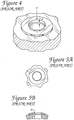
- the effective operating travel is limited because the compressive hoop stress (the bending stress at the convex inner edge) of the washer ("C" - Fig. 4) typically exceeds the compressive yield strength of the washer material at very small deflection values.
- the tensile hoop stress (the bending stress at the outer edge) (“T") typically exceeds the tensile strength of the washer material at these small deflections. If either or both of these situations occur, the washer material reaches the plastic state; the washer does not return to its original form and loses some or all of its spring properties.
- Belleville spring washers are used to maintain a predefined clamping force on the clamped members within a predetermined range of differential motion of the member on each side of the washer.
- Belleville washers are also used in applications where they are initially flattened but become the predominant clamping force when the clamped and clamping members experience conditions that cause them to lose their initial stress (for example when the members are subjected to vibration and/or to temperature changes and thermal gradients causing differential expansion and/or contraction of members).
- the large thermal cycles and gradients (approx. 300°C) between components experienced in processing semiconductor wafers (at normal temperatures of 400-500°C) can and do cause fastening systems unable to accommodate the differential movement to fail (e.g., causing loss of electrical conductance and/or loss of vessel pressure integrity).
- the invention therefore provides a fastener component according to independent claims 1 or 4, a method of assuring electrical connection between components according to independent claim 12 and fasteners according to independent claims 13 or 17. Further advantageous features, aspects and details of the invention are evident from the dependent claims, the description and the drawings. The claims are intended to be understood as a first non-limiting approach of defining the invention in general terms.
- the invention provides a slotted conical spring washer and generally lies in the field of spring washers as they are used with fasteners and in fastening systems.
- a structure and system of this invention provide for an increased range of available deflection in applications where Belleville washers may have been used in the past.
- a split or slot is provided in one side of a conical (domed, convex, or other non-flat) spring washer.
- the split or slot releases the constraints on compressive and tensile hoop stresses that cause the material in a Belleville spring washer to yield and plastically deform.
- a ring encircling the outside diameter of the slotted spring washer prevents the split conical spring washer (also known as a strip or band encircling a bore) from seeking its lowest energy condition and unravelling as it is being compressed.
- the ring constraining the outside diameter of the spring washer can be a flat washer with a peripheral flange.
- the flange will act as a ring to constrain the washer or strip from radially moving away from the center of the bore of the washer.
- the ring can also be part of the member to be clamped.
- a counter bore can be provided in the member to be clamped around the hole for the clamping member (bolt or stud). When the slotted spring washer is placed in this counter bore, the radial movement of the outside diameter of the washer or strip or band is restricted.
- the ring can also be integral with the conical spring washer.
- the split or slot in the conical spring washer in this configuration appears not to go all the way through from the inside diameter of the washer to the outside diameter.
- the ring constraining the outside diameter of the ring preferably is integral and continuous with the outside diameter of the spring washer.
- the two ends of the washer strip or band advantageously are connected by a portion of the ring called a tie at the outside diameter of the washer across the slot. Sharp corners, where the end of the slot meets the tie portion of the ring, could produce stress concentrations resulting in premature failure of the ring. Long radiuses and smooth transitions are beneficial in order to avoid stress concentration factors.
- the slotted conical spring washer of one aspect of this invention should be constructed of a material that is not severely degraded by such an environment, such as Inconel, nickel plated Inconel, Hastalloy, Haynes alloys, or other material with suitable chemical resisting and mechanical strength properties at high temperatures.
- the slotted washer material have a yield strength in excess of 7030 kg/cm (100 ksi) at operating temperature.
- the slotted conical spring washer fastening system can be effectively used to increase the clamping performance of clamping systems by utilizing the slotted spring washer in a method to assure that electrical or fluid tight connections between components are maintained.
- the steps of the method preferably include: assembling a set of members to be clamped in the position which the members are to be clamped, placing a slotted spring washer fastening system at an end of a clamping member (bolt, stud or other rod like member), and compressing the slotted spring washer together with the set of members to be clamped and securing the clamping members where they provide a predetermined clamping force to said members to be clamped including the slotted spring washer.
- a spring washer fastening system and method according to the invention provide operational and design advantages over the prior art.
- the stresses in the washer remain in the elastic range of the materials used throughout the load range, even when the washer is flattened.
- the spring washer system can be used repeatedly in applications where a greatly increased operable spring range is desired over many hundreds of cycles before replacement.
- a washer according to the invention will also occupy less space than similarly performing prior art washers. Member sizes can be reduced when fasteners occupy less space.
- the standard Belleville washer as shown in Figs. 4, 5A, and 5B in their standard configuration are constructed with available deflections "d" (as seen in Table A below) between 0.152 and 0.381 mm (0.006 and 0.015 inches) when manufactured.
- available deflections "d" as seen in Table A below
- the actual deflection of the Belleville washer exceeds 0.076 mm (0.003 inches)
- the hoop stress in the washer exceeds the yield strength of the material.
- the washer material will plastically deform and the washer can only recover approximately 0.076 mm (0.003 inches) from its maximum deflection.
- the maximum elastic recovery is also approximately 0.076 mm (0.003 inches) and no more.
- the actual usable available deflection is only 0.076 mm (0.003 inches).
- a conical spring washer fastening system when configured according to this invention is capable of having a available deflection five times (5x) 0.381 mm vs.
- TABLE A shows the maximum loads available for the available deflections.
- the load bending stress versus deflection relationships for a slotted washer according to the invention as shown in column #4 of TABLE A are approximated according to calculations in TABLE B.
- TABLE B (English) Deflection in Load lbs Bending Stress psi 0.001 47 10 0.002 92 20 0.003 135 30 0.004 177 40 0.005 218 50 0.006 257 60 0.007 295 70 0.008 332 80 0.009 368 90 0.01 404 100 0.011 439 110 0.012 473 120 0.013 507 130 0.014 540 140 0.015 574 150
- Belleville or other spring type washers can be combined or chosen to achieve the force and usable available deflection required for given applications.
- the space required to utilize prior art spring washers for a given application is large compared to the space required to achieve the same performance from a washer (fastening) configuration according to the invention.
- a set of given conditions can only be achieved if a 15.875 mm (0.625 in.) or 19.05 mm (0.75 in.) outside diameter spring washer is used.
- a washer configuration according to the invention would require only a 9.525 mm (0.375 in.) outside diameter washer.
- FIG. 1 An embodiment of the invention is shown in Figure 1.
- a conical (or domed) slotted (or split) spring washer 20 is disposed in the counter bore 51 of a member to be clamped 52.
- a clamping member (such as a bolt) exerts a force "F" on the washer 20.
- the available deflection "d" of the washer can be observed at the inside diameter of the washer 20.
- the washer 20 consists of a generally flat strip or band of material 30 encircling a bore 37 (Fig. 8) or a curved strip or band of material 30A encircling the bore 37, creating a domed shape (Fig. 8A).
- the strip is generally made of material suitable for an extended life in those environments.
- Figure 11 shows the embodiment of Figure 1 with a clamping member (bolt) 54 in position to be fastened.
- the strip can be a generally flat material which has been formed into a cone or dome shape and is preferably made of Inconel-750 which has been annealed, heat treated to full spring temper and has a sulfamate nickel electroplate finish 0.076 - 0.127 mm (0.003 - 0.005 in.) thick.
- the slotted washer has an outside diameter of 9.652 + 0.127/ - .254 mm (0.380 +.005/-.010 in.), an inside diameter of 0.533mm (0.210 in.), a slot width of 1.143 ⁇ 0.381 mm (.045 ⁇ 0.015 in.), a strip thickness (33) of 0.762 ⁇ 0.004 mm (0.030 ⁇ 0.0015 in.), and an overall free thickness (27) of 1.143 ⁇ 0.076mm (0.045 ⁇ .003 in.) as shown in Figures 9 and 10.
- the retainer washer has an outside diameter of 10.973 ⁇ 0.05 mm (0.432 ⁇ .002 in.), and inside diameter of 0.533 mm (0.210 in.), a flanged bore inside diameter (46) of 9.96 ⁇ 0.051 mm (0.392 ⁇ 0.002 in.), flat washer thickness (48) of 0.508 mm (0.020 in.), and a flange height of 9.76 mm (0.030 in.). This is the basic configur ation of a standard #10 washer.
- the washer outside diameter is larger than the largest dimension of a bolt, screw, or nut head. Therefore, in normal use, there can be no interference between the bolt, screw, or nut head and the counter bore in which the washer is placed. However, if a bolt, screw, or nut head is used that protrudes over the outside edge of the washer, care must be taken to be sure that the configuration provides no interference between pieces.
- a retaining washer ring 44 can be used (Figs. 3A,3B,3C,9, and 10).
- the retaining washer 44 includes a ring 22 to restrain the expansion of the slotted spring washer 20.
- the ring 22 is formed by an flat disk washer having an annular flange 47.
- the flat disk has a center hole that centers the annular flange (ring) on the bolt hole.
- the flange height 50 in excess of the flat disk thickness 48 approximately equals the washer strip material thickness, e.g., 0.762 mm (0.030 in.), the flat washer thickness 48 is 0.508 mm (0.020 in.) and the flange thickness 49 is approximately 1.016 mm (0.040 in.).
- the preferred clearance between the inside diameter of the retaining ring (whether it be a counter bore inside diameter or a retaining ring inside diameter) and the outside diameter of the slotted conical washer is approximately 0.127 to 0.635 mm (0.005 to 0.025 in.).
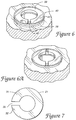
- the slotted spring washer and its encircling ring can be integrally formed as shown by the configuration pictured in Figure 6.
- the integral washer/ring 40 includes a washer portion 39 and a ring portion 41.
- the imaginary dashed line shown separates the washer portion 39 from the ring portion.
- Carefully formed radiuses 43 and smooth transitions are some of the techniques that are used to reduce stress concentration factors at the potentially sharp transitions between the slot and the tie.
- a flat washer 38 (as shown in dotted lines) can be provided on one side of the washer to prevent the washer edges from digging into and damaging the material of the member to be clamped when the material is soft (e.g. aluminum with a low yield stress).
- each additional slot reduces the material area available to support a load and reduces the washer internal stresses which are a substantial factor contributing to the washer's load bearing capacity.
- the invention therefore provides a slotted conical (non-flat) spring washer with an encircling ring provides improved spring washer performance.
- the split or slotted conical spring washer is encircled by a retaining ring that prevents the ends of the washer adjacent to the slot from expanding as the washer is compressed. The ends of the washer on both sides of the slot move to prevent the washer material from exceeding its yield strength.
- the ring restricts the radial movement of said outside diameter of the washer strip away from a center axis of the washer bore.
- the ring can be a counter bore in a member to be clamped, a retaining washer having an outside annular washer to act as the ring, or can be integral with the spring washer such that the slot appears not to pass completely through the washer strip.
- This slotted conical spring washer greatly increases the elastic spring travel available during repeated clamping cycles and during movement of clamped members due to differences in rates of thermal expansion and thermal gradients.
- a method for using the slotted spring washer fastening system invention assures electrical conductance and/or fluid vessel integrity under high temperatures and thermal gradients and when different materials are used in the clamped and clamping members.
Landscapes
- Engineering & Computer Science (AREA)
- General Engineering & Computer Science (AREA)
- Mechanical Engineering (AREA)
- Bolts, Nuts, And Washers (AREA)
Applications Claiming Priority (2)
| Application Number | Priority Date | Filing Date | Title |
|---|---|---|---|
| US08/094,674 US5496142A (en) | 1993-07-20 | 1993-07-20 | Slotted conical spring washer |
| US94674 | 1993-07-20 |
Publications (2)
| Publication Number | Publication Date |
|---|---|
| EP0636802A2 true EP0636802A2 (de) | 1995-02-01 |
| EP0636802A3 EP0636802A3 (de) | 1996-08-21 |
Family
ID=22246499
Family Applications (1)
| Application Number | Title | Priority Date | Filing Date |
|---|---|---|---|
| EP94111338A Withdrawn EP0636802A3 (de) | 1993-07-20 | 1994-07-20 | Befestigungselement und dessen Benutzung. |
Country Status (4)
| Country | Link |
|---|---|
| US (1) | US5496142A (de) |
| EP (1) | EP0636802A3 (de) |
| JP (1) | JPH0771433A (de) |
| KR (1) | KR950003646A (de) |
Cited By (2)
| Publication number | Priority date | Publication date | Assignee | Title |
|---|---|---|---|---|
| US20230001496A1 (en) * | 2019-12-05 | 2023-01-05 | Milwaukee Electric Tool Corporation | Circular saw blade holder |
| US12595115B2 (en) | 2023-01-17 | 2026-04-07 | Milwaukee Electric Tool Corporation | Circular saw blade holder |
Families Citing this family (56)
| Publication number | Priority date | Publication date | Assignee | Title |
|---|---|---|---|---|
| FR2738317B1 (fr) * | 1995-08-31 | 1997-10-17 | Soframca | Piston a clapet flottant pour tube d'amortisseur hydraulique, notamment de type monotube |
| US6135850A (en) * | 1997-12-29 | 2000-10-24 | Reed; Gerald D. | Lighted toy and safety method |
| US5915875A (en) * | 1998-06-19 | 1999-06-29 | General Motors Corporation | End play take up retaining ring |
| RU2144630C1 (ru) * | 1999-06-22 | 2000-01-20 | Закрытое акционерное общество "Интеллект" | Шайба |
| RU2144632C1 (ru) * | 1999-06-22 | 2000-01-20 | Закрытое акционерное общество "Интеллект" | Шайба |
| RU2144631C1 (ru) * | 1999-06-22 | 2000-01-20 | Закрытое акционерное общество "Интеллект" | Шайба пружинная |
| RU2144149C1 (ru) * | 1999-06-24 | 2000-01-10 | Закрытое акционерное общество "Интеллект" | Шайба слоистая |
| RU2144151C1 (ru) * | 1999-06-24 | 2000-01-10 | Закрытое акционерное общество "Интеллект" | Шайба слоистая |
| RU2144150C1 (ru) * | 1999-06-24 | 2000-01-10 | Закрытое акционерное общество "Интеллект" | Шайба пружинная слоистая |
| US6237457B1 (en) * | 2000-02-02 | 2001-05-29 | Taylor Design Group, Inc. | Apparatus for precisely guiding a workpiece relative to a work surface |
| US6705813B2 (en) * | 2002-02-07 | 2004-03-16 | Pierre P. Schwab | Snap disc device |
| US7879075B2 (en) * | 2002-02-13 | 2011-02-01 | Zimmer Spine, Inc. | Methods for connecting a longitudinal member to a bone portion |
| DE20206373U1 (de) * | 2002-04-23 | 2002-08-08 | Textron Verbindungstechnik GmbH & Co. oHG, 56567 Neuwied | Selbstsichernde Befestigungseinrichtung |
| USD528407S1 (en) * | 2003-02-03 | 2006-09-19 | Schwab Pierre P | Snap disc element |
| DE20302520U1 (de) * | 2003-02-17 | 2004-06-24 | Arvin Technologies Inc., Columbus | Ventil für eine Abgasleitung |
| US7008325B2 (en) * | 2003-10-08 | 2006-03-07 | Automotive Components Holdings, Inc. | Retainer ring for tripod constant velocity joints |
| JP4669507B2 (ja) * | 2005-02-15 | 2011-04-13 | 富士通株式会社 | バネ加圧ユニット |
| US7198445B2 (en) * | 2005-06-03 | 2007-04-03 | Fan Disc Corporation | Washer with crush zone |
| US8579807B2 (en) | 2008-04-28 | 2013-11-12 | Ethicon Endo-Surgery, Inc. | Absorbing fluids in a surgical access device |
| USD700326S1 (en) | 2008-04-28 | 2014-02-25 | Ethicon Endo-Surgery, Inc. | Trocar housing |
| US8568362B2 (en) * | 2008-04-28 | 2013-10-29 | Ethicon Endo-Surgery, Inc. | Surgical access device with sorbents |
| US8636686B2 (en) | 2008-04-28 | 2014-01-28 | Ethicon Endo-Surgery, Inc. | Surgical access device |
| US8273060B2 (en) | 2008-04-28 | 2012-09-25 | Ethicon Endo-Surgery, Inc. | Fluid removal in a surgical access device |
| US8870747B2 (en) * | 2008-04-28 | 2014-10-28 | Ethicon Endo-Surgery, Inc. | Scraping fluid removal in a surgical access device |
| US11235111B2 (en) | 2008-04-28 | 2022-02-01 | Ethicon Llc | Surgical access device |
| US9358041B2 (en) | 2008-04-28 | 2016-06-07 | Ethicon Endo-Surgery, Llc | Wicking fluid management in a surgical access device |
| CN101900159B (zh) * | 2010-07-08 | 2012-05-23 | 山东伟基炭科技有限公司 | 防止高温下螺栓连接组件失效的方法及所采用的卸载装置 |
| US8616818B2 (en) | 2011-02-17 | 2013-12-31 | Raytheon Company | Gripping washer having one or more deformable gripping tabs and method for reducing foreign object debris |
| US8740949B2 (en) | 2011-02-24 | 2014-06-03 | Spinal Elements, Inc. | Methods and apparatus for stabilizing bone |
| USD739935S1 (en) | 2011-10-26 | 2015-09-29 | Spinal Elements, Inc. | Interbody bone implant |
| DE102012205892A1 (de) * | 2012-04-11 | 2013-10-17 | Bayerische Motoren Werke Aktiengesellschaft | Vorgespannte Formschlussverbindung |
| USD692747S1 (en) | 2013-03-13 | 2013-11-05 | Pierre P. Schwab | Disc spring |
| USD812109S1 (en) | 2013-03-13 | 2018-03-06 | Deer & Company | Gang tension spring washer for an agricultural machine |
| US9421044B2 (en) | 2013-03-14 | 2016-08-23 | Spinal Elements, Inc. | Apparatus for bone stabilization and distraction and methods of use |
| US9456855B2 (en) | 2013-09-27 | 2016-10-04 | Spinal Elements, Inc. | Method of placing an implant between bone portions |
| US9839450B2 (en) | 2013-09-27 | 2017-12-12 | Spinal Elements, Inc. | Device and method for reinforcement of a facet |
| US11478275B2 (en) | 2014-09-17 | 2022-10-25 | Spinal Elements, Inc. | Flexible fastening band connector |
| WO2016081528A1 (en) * | 2014-11-17 | 2016-05-26 | Bridging Medical, Llc | Bone compression systems |
| FR3035160B1 (fr) * | 2015-04-17 | 2018-03-23 | Centre Technique Des Industries Mecaniques | Ensemble a vis deformable |
| KR101693141B1 (ko) * | 2016-01-27 | 2017-01-04 | 유학성 | 매립형 연결 고정구 |
| CN106640911A (zh) * | 2016-12-01 | 2017-05-10 | 陈卫江 | 一种斜面自锁螺母 |
| US10408250B2 (en) | 2017-02-08 | 2019-09-10 | The Boeing Company | Load-indicating washer |
| KR102004612B1 (ko) * | 2017-09-21 | 2019-07-26 | 서울시립대학교 산학협력단 | 축력 직접 확인가능 와셔 시스템 |
| US11060578B2 (en) | 2018-05-22 | 2021-07-13 | Allison Transmission, Inc. | Conical spring washer, transmission system, and method of assembly thereof |
| GB2581322B (en) * | 2018-12-23 | 2022-09-21 | Secheron Hasler Uk Ltd | A device for the transfer of electric current including a contact washer |
| AU2020278453A1 (en) | 2019-05-22 | 2022-01-20 | Spinal Elements, Inc. | Bone tie and bone tie inserter |
| US11457959B2 (en) | 2019-05-22 | 2022-10-04 | Spinal Elements, Inc. | Bone tie and bone tie inserter |
| US20200321730A1 (en) * | 2019-06-21 | 2020-10-08 | Intel Corporation | Small form factor connection mechanism for a card to card connector |
| USD1033644S1 (en) | 2019-09-11 | 2024-07-02 | Medline Industries, Lp | Deformable medical compression device |
| US11510713B2 (en) | 2019-09-11 | 2022-11-29 | Medline Industries, Lp | Compression device, kit, and method |
| WO2021163313A1 (en) | 2020-02-14 | 2021-08-19 | Spinal Elements, Inc. | Bone tie methods |
| US11547441B2 (en) * | 2020-02-20 | 2023-01-10 | Covidien Lp | Retention anchor for surgical access devices |
| US11207916B2 (en) * | 2020-05-26 | 2021-12-28 | Other World Computing, Inc. | Coupling mechanism and supporting assembly including the same |
| US11974789B2 (en) | 2021-06-21 | 2024-05-07 | Medline Industries, Lp | Compression device, bone plate, bone plate assembly, kit, and method |
| US12369952B2 (en) | 2021-12-10 | 2025-07-29 | Spinal Elements, Inc. | Bone tie and portal |
| CN114962425A (zh) * | 2022-05-06 | 2022-08-30 | 东风柳州汽车有限公司 | 垫圈组件和汽车 |
Family Cites Families (13)
| Publication number | Priority date | Publication date | Assignee | Title |
|---|---|---|---|---|
| US1394740A (en) * | 1920-02-27 | 1921-10-25 | Harry F Hughes | Nut-lock |
| DE687464C (de) * | 1936-12-04 | 1940-01-30 | Alfred Von Koharovich | mittels federnder Spannglieder zwischen Mutter und Werkstueck |
| US2464152A (en) * | 1943-09-11 | 1949-03-08 | Ralston Eldon Kipp | Tension indicating means |
| US2771591A (en) * | 1953-05-25 | 1956-11-20 | Chance Co Ab | Electrical drawbolt type connector with constant load washer |
| US2779375A (en) * | 1955-05-04 | 1957-01-29 | Illinois Tool Works | Split washer having one helical margin and one planar margin adapted to be secured to threaded fastener |
| US3009176A (en) * | 1957-07-18 | 1961-11-21 | Louis T Knocke | Method of assembly of bolt and washer |
| US2996735A (en) * | 1957-12-23 | 1961-08-22 | Louis T Knocke | Method for securing a plated washer to a plated nut or bolt by fusing the platings |
| US3041574A (en) * | 1958-07-28 | 1962-06-26 | Penn Union Electric Corp | Transformer connector |
| US3503430A (en) * | 1968-05-29 | 1970-03-31 | Ichizo Tsurumoto | Annular spring lock washer |
| US3800396A (en) * | 1972-07-21 | 1974-04-02 | Charter Mfg Co | Method of assembling and using a prearranged fastening element package |
| JPS6025648B2 (ja) * | 1977-06-20 | 1985-06-19 | 理雄 安部 | ヘリカル・コニカル・スプリング・ロツク・ワツシヤ− |
| US4958970A (en) * | 1988-08-17 | 1990-09-25 | The United States Of America As Represented By The Secretary Of The Navy | Graduated-load spring washer system for screws and threaded fasteners |
| US5316319A (en) * | 1992-09-22 | 1994-05-31 | Rm Engineered Products, Inc. | Liveload assembly for maintaining torque on bolts |
-
1993
- 1993-07-20 US US08/094,674 patent/US5496142A/en not_active Expired - Lifetime
-
1994
- 1994-07-20 JP JP6168300A patent/JPH0771433A/ja not_active Withdrawn
- 1994-07-20 KR KR1019940017472A patent/KR950003646A/ko not_active Withdrawn
- 1994-07-20 EP EP94111338A patent/EP0636802A3/de not_active Withdrawn
Cited By (2)
| Publication number | Priority date | Publication date | Assignee | Title |
|---|---|---|---|---|
| US20230001496A1 (en) * | 2019-12-05 | 2023-01-05 | Milwaukee Electric Tool Corporation | Circular saw blade holder |
| US12595115B2 (en) | 2023-01-17 | 2026-04-07 | Milwaukee Electric Tool Corporation | Circular saw blade holder |
Also Published As
| Publication number | Publication date |
|---|---|
| EP0636802A3 (de) | 1996-08-21 |
| KR950003646A (ko) | 1995-02-17 |
| US5496142A (en) | 1996-03-05 |
| JPH0771433A (ja) | 1995-03-17 |
Similar Documents
| Publication | Publication Date | Title |
|---|---|---|
| US5496142A (en) | Slotted conical spring washer | |
| US6945539B2 (en) | Seal retainer | |
| US4571133A (en) | Loading washer assembly | |
| US5240263A (en) | Metallic sealing rings and their manufacture | |
| US6513814B2 (en) | Stress induced connecting assembly | |
| EP1105250B1 (de) | Hochtemperatur verschraubungssystem | |
| US5927921A (en) | Enhanced fatigue nut | |
| JPH07113392B2 (ja) | 弾性荷重支持および運動調整マウント部材 | |
| US3375000A (en) | Belleville spring assembly | |
| CN108190051A (zh) | 一种sma丝驱动的超大载荷解锁装置 | |
| US4331367A (en) | Sealed compound bearing | |
| EP0233938B1 (de) | Verfahren zum einbau von nieten und deren form | |
| CN1124993A (zh) | 用于大型建筑物的移动阻尼器 | |
| JPH08500887A (ja) | 金属密封素子 | |
| JPS634042B2 (de) | ||
| US20030084572A1 (en) | Spherical bearing and a manufacturing method thereof | |
| GB2087503A (en) | Temperature compensating spacer | |
| JP3410011B2 (ja) | 平型半導体素子用スタック | |
| CN110763091B (zh) | 一种用于级间线式分离装置的非对称v型槽、双点解锁式刚性包带 | |
| US3649000A (en) | Helical coil spring arrangement | |
| JPH09105440A (ja) | 免震装置 | |
| CN111365353B (zh) | 一种自锁防松垫圈、螺栓组件及安装方法 | |
| CN217177242U (zh) | 一种碟形波簧 | |
| US5429338A (en) | Equipment mount | |
| JP2000507334A (ja) | 弾性止め座金 |
Legal Events
| Date | Code | Title | Description |
|---|---|---|---|
| PUAI | Public reference made under article 153(3) epc to a published international application that has entered the european phase |
Free format text: ORIGINAL CODE: 0009012 |
|
| AK | Designated contracting states |
Kind code of ref document: A2 Designated state(s): DE GB |
|
| PUAL | Search report despatched |
Free format text: ORIGINAL CODE: 0009013 |
|
| AK | Designated contracting states |
Kind code of ref document: A3 Designated state(s): DE GB |
|
| STAA | Information on the status of an ep patent application or granted ep patent |
Free format text: STATUS: THE APPLICATION IS DEEMED TO BE WITHDRAWN |
|
| 18D | Application deemed to be withdrawn |
Effective date: 19970222 |