EP0637116A1 - Schutzvorrichtung für Kabelspleiss - Google Patents
Schutzvorrichtung für Kabelspleiss Download PDFInfo
- Publication number
- EP0637116A1 EP0637116A1 EP94305504A EP94305504A EP0637116A1 EP 0637116 A1 EP0637116 A1 EP 0637116A1 EP 94305504 A EP94305504 A EP 94305504A EP 94305504 A EP94305504 A EP 94305504A EP 0637116 A1 EP0637116 A1 EP 0637116A1
- Authority
- EP
- European Patent Office
- Prior art keywords
- open end
- inner shell
- cable splice
- cable
- outer shell
- Prior art date
- Legal status (The legal status is an assumption and is not a legal conclusion. Google has not performed a legal analysis and makes no representation as to the accuracy of the status listed.)
- Granted
Links
- 230000001012 protector Effects 0.000 title claims abstract description 64
- 230000000295 complement effect Effects 0.000 claims description 23
- 238000000034 method Methods 0.000 claims description 13
- UQMRAFJOBWOFNS-UHFFFAOYSA-N butyl 2-(2,4-dichlorophenoxy)acetate Chemical compound CCCCOC(=O)COC1=CC=C(Cl)C=C1Cl UQMRAFJOBWOFNS-UHFFFAOYSA-N 0.000 description 24
- 230000006835 compression Effects 0.000 description 9
- 238000007906 compression Methods 0.000 description 9
- 238000000429 assembly Methods 0.000 description 8
- 238000007789 sealing Methods 0.000 description 7
- 239000000463 material Substances 0.000 description 6
- 239000004033 plastic Substances 0.000 description 6
- 229920003023 plastic Polymers 0.000 description 6
- 239000000356 contaminant Substances 0.000 description 5
- 230000008878 coupling Effects 0.000 description 5
- 238000010168 coupling process Methods 0.000 description 5
- 238000005859 coupling reaction Methods 0.000 description 5
- 230000007704 transition Effects 0.000 description 3
- XLYOFNOQVPJJNP-UHFFFAOYSA-N water Substances O XLYOFNOQVPJJNP-UHFFFAOYSA-N 0.000 description 3
- 239000000919 ceramic Substances 0.000 description 2
- 239000002184 metal Substances 0.000 description 2
- 229910052751 metal Inorganic materials 0.000 description 2
- 150000002739 metals Chemical class 0.000 description 2
- 239000000126 substance Substances 0.000 description 2
- 239000004677 Nylon Substances 0.000 description 1
- 239000004809 Teflon Substances 0.000 description 1
- 229920006362 Teflon® Polymers 0.000 description 1
- 239000000853 adhesive Substances 0.000 description 1
- 230000001070 adhesive effect Effects 0.000 description 1
- 238000010276 construction Methods 0.000 description 1
- 229920001778 nylon Polymers 0.000 description 1
- 230000001681 protective effect Effects 0.000 description 1
- 238000004513 sizing Methods 0.000 description 1
- 229910000679 solder Inorganic materials 0.000 description 1
Images


Classifications
-
- H—ELECTRICITY
- H01—ELECTRIC ELEMENTS
- H01R—ELECTRICALLY-CONDUCTIVE CONNECTIONS; STRUCTURAL ASSOCIATIONS OF A PLURALITY OF MUTUALLY-INSULATED ELECTRICAL CONNECTING ELEMENTS; COUPLING DEVICES; CURRENT COLLECTORS
- H01R13/00—Details of coupling devices of the kinds covered by groups H01R12/70 or H01R24/00 - H01R33/00
- H01R13/46—Bases; Cases
- H01R13/52—Dustproof, splashproof, drip-proof, waterproof, or flameproof cases
- H01R13/5205—Sealing means between cable and housing, e.g. grommet
- H01R13/5208—Sealing means between cable and housing, e.g. grommet having at least two cable receiving openings
-
- H—ELECTRICITY
- H01—ELECTRIC ELEMENTS
- H01R—ELECTRICALLY-CONDUCTIVE CONNECTIONS; STRUCTURAL ASSOCIATIONS OF A PLURALITY OF MUTUALLY-INSULATED ELECTRICAL CONNECTING ELEMENTS; COUPLING DEVICES; CURRENT COLLECTORS
- H01R13/00—Details of coupling devices of the kinds covered by groups H01R12/70 or H01R24/00 - H01R33/00
- H01R13/02—Contact members
- H01R13/10—Sockets for co-operation with pins or blades
- H01R13/11—Resilient sockets
- H01R13/115—U-shaped sockets having inwardly bent legs, e.g. spade type
-
- H—ELECTRICITY
- H01—ELECTRIC ELEMENTS
- H01R—ELECTRICALLY-CONDUCTIVE CONNECTIONS; STRUCTURAL ASSOCIATIONS OF A PLURALITY OF MUTUALLY-INSULATED ELECTRICAL CONNECTING ELEMENTS; COUPLING DEVICES; CURRENT COLLECTORS
- H01R4/00—Electrically-conductive connections between two or more conductive members in direct contact, i.e. touching one another; Means for effecting or maintaining such contact; Electrically-conductive connections having two or more spaced connecting locations for conductors and using contact members penetrating insulation
- H01R4/70—Insulation of connections
-
- H—ELECTRICITY
- H02—GENERATION; CONVERSION OR DISTRIBUTION OF ELECTRIC POWER
- H02G—INSTALLATION OF ELECTRIC CABLES OR LINES, OR OF COMBINED OPTICAL AND ELECTRIC CABLES OR LINES
- H02G15/00—Cable fittings
- H02G15/08—Cable junctions
- H02G15/10—Cable junctions protected by boxes, e.g. by distribution, connection or junction boxes
- H02G15/115—Boxes split perpendicularly to main cable direction
-
- H—ELECTRICITY
- H02—GENERATION; CONVERSION OR DISTRIBUTION OF ELECTRIC POWER
- H02G—INSTALLATION OF ELECTRIC CABLES OR LINES, OR OF COMBINED OPTICAL AND ELECTRIC CABLES OR LINES
- H02G15/00—Cable fittings
- H02G15/08—Cable junctions
- H02G15/18—Cable junctions protected by sleeves, e.g. for communication cable
- H02G15/192—Cable junctions protected by sleeves, e.g. for communication cable with support means for ends of the sleeves
-
- H—ELECTRICITY
- H01—ELECTRIC ELEMENTS
- H01R—ELECTRICALLY-CONDUCTIVE CONNECTIONS; STRUCTURAL ASSOCIATIONS OF A PLURALITY OF MUTUALLY-INSULATED ELECTRICAL CONNECTING ELEMENTS; COUPLING DEVICES; CURRENT COLLECTORS
- H01R13/00—Details of coupling devices of the kinds covered by groups H01R12/70 or H01R24/00 - H01R33/00
- H01R13/58—Means for relieving strain on wire connection, e.g. cord grip, for avoiding loosening of connections between wires and terminals within a coupling device terminating a cable
- H01R13/5804—Means for relieving strain on wire connection, e.g. cord grip, for avoiding loosening of connections between wires and terminals within a coupling device terminating a cable comprising a separate cable clamping part
- H01R13/5812—Means for relieving strain on wire connection, e.g. cord grip, for avoiding loosening of connections between wires and terminals within a coupling device terminating a cable comprising a separate cable clamping part the cable clamping being achieved by mounting the separate part on the housing of the coupling device
Definitions
- This invention concerns a reusable apparatus for protecting a cable splice from the elements, and especially for protecting cable splices that are to be buried.
- This invention is also a method for protecting a spliced cable with the apparatus of this invention.
- the cable splice protector of this invention is easily associated with separate ends of a cable or cables to be spliced.
- the apparatus of this invention is associated with the cable splice in a manner that protects the splice site from moisture, dirt, and other contaminants.
- Kits for protecting cable splices are well known in the prior art.
- One form of cable splice protector kit uses shrink-wrap.
- the shrink-wrap kit typically include a connector for uniting two ends of a cable, a cylindrical rubber piece the surrounds the connector, and a cylindrical piece of shrink wrap that is applied to the rubber covered connector to seal the splice from the elements.
- Such shrink-wrap based cable splice protector kits require a heat source in order to apply the shrink wrap.
- the protective sheath formed by the shrink wrap is not reusable.
- a transition sealing device is available in the prior art that is able to seal a cable transition through a wall or a panel.
- the cable transition sealing device includes a shell having a threaded end complementary to a wall or panel, and end having a collet.
- a sealing nut is complementary to the collet. The union of the sealing nut and the collet compresses and seals a cable passing through the fitting.
- U.S. Patent 4,684,764 to Luzzi et al. describes a two piece locking housing for protecting a high voltage cable splice.
- the locking housing uses rolled end seals to prevent dirt and moisture from entering the housing.
- U.S. Patent 3,854,003 to Duret describes a connector for joining two ends of a co-axial cable.
- the connector uses an annular wedge combined with a shell to mechanically clamp and secure the cable.
- the connector does not include any type of seal to protect the connection from dirt and moisture.
- U.S. Patent 3,573,346 to Appleby discloses a strain relief coupling.
- the strain relief coupling includes an ellipsoidal member that is made up of armor rods overlying
- U.S. Patent 3,573,346 to Appleby discloses a strain relief coupling.
- the strain relief coupling includes an ellipsoidal member that is made up of armor rods overlying an inner shell.
- the cable is surrounded by the ellipsoidal member which, when united with the coupling housing transfers all strain from the cable to the housing.
- U.S. Patent 3,381,082 to Peterson describes a cable splicer.
- the cable splicer described includes a plastic like substance that encases a striped, end portion of a cable. A compressive force is applied to the plastic like substance to produce a tight, gas proof seal.
- U.S. Patent 2,239,026 to Wagner describes a cable connector including two insulated members that are united with a threaded cylindrical member.
- U.S. Patent 2,001,131 to Guhl describes a connector that is associated with a cable without solder.
- the connector includes to female members that are united with a single male member to form a connector housing.
- U.S. Patent 1,718,817 to Greene describes a cable connector.
- the cable is sealed into the cable connector by a single compression point.
- a wedge-ring is inserted into the end of the insulated wire and a compression ring, acting in concert with a collar, secures the cable into place.
- this invention is a cable splice protector comprising a hollow first inner shell, a hollow second inner shell, a hollow first outer shell, and a hollow second outer shell.
- the hollow first inner shell includes first inner shell body having a first open end and an opposing second open end.
- the second open end has a smaller cross-sectional area than the first open end and includes an apertured grommet surrounded by a compressible wall.
- the first open end includes a seal.
- the cable splice protector also includes a hollow second inner shell having a first open end and an opposing second open end.
- the second open end has a smaller cross-sectional area than the first open end and includes a compressible wall surrounding a compressible grommet.
- the cable splice protector also includes a hollow first outer shell having a recess large enough to contain the hollow first inner shell.
- the first outer shell has a first open end and a second open end.
- the second open end has a smaller cross-sectional area than the first open end and includes an inwardly tapered shoulder.
- the first open end of the first outer shell includes a variable connector.
- the cable splice protector includes a second outer shell with a recess large enough to encompass the hollow second inner shell.
- the second outer shell has a first open end and a second open end having a smaller cross-sectional area than the first open end and including an inwardly tapered shoulder.
- the second outer shell includes a second variable connector complementary to the first variable connector.
- this invention is a method of protecting at least one cable splice with a cable splice protector.
- the cable splice protector useful in this invention includes a first inner shell having a first open end and an opposing second open end having a smaller cross sectional area than the first open end.
- the second open end consists of a compressible wall surrounding an apertured grommet located inside the compressible wall.
- the cable splice protector includes a second inner shell having a first open end and an opposing second open end having a smaller cross sectional area than the first open end.
- the cable splice protector further includes a first outer shell and a second outer shell each having a recess large enough to contain the first inner shell and a second inner shell respectively.
- Both the first outer shell and the second outer shell have a first open end and a second open end having a smaller cross sectional area than the first open end and both include an inwardly tapered shoulder associated with the second open end.
- the first outer shell and the second outer shell have complimentary variable connectors.
- One method of this invention uses a first cable shield sub-assembly and a second cable shield sub-assembly to protect a cable splice.
- the first cable shield sub-assembly comprises an apertured grommet associated with the inner dimension of the compressible wall of the first inner shell which in turn is located in the recess defined by the first outer shell.
- the second cable shield sub-assembly comprises an apertured grommet located in the inner dimension of the compressible wall of the second inner shell.
- the second inner shell in turn, is located in the second outer shell.
- the first cable shield sub-assembly and the second cable shield sub-assembly are then associated with an end of a first cable and an end of a second cable respectively.
- the end of the first and second cables are associated with the first and second cable shield sub-assemblies such that the ends of first and second the cables pass through the second end of the outer shell, the second end of the inner shell, and then pass through an aperture in aperture grommet of the first and second cable shield sub-assemblies.
- the end of the cable is passed out of the first opening of the inner shell and out of the first opening of the outer shell.
- at least one cable splice is made.
- the first and second cable shield sub-assemblies are compressively united using the variable connector to seal the splice site from water and other contaminants.
- a cable splice is protected from water and other contaminants using the cable splice protector of this invention by uniting the various parts of the cable splice protector with an end of a first or second cable as the cable splice protector is being assembled.
- an end of a first cable to be spliced is directed through the second end of a first outer shell, through an aperture associated with an apertured grommet, and through the second end of a first inner shell.
- an end of a second cable is passed through the second end of a second outer shell, through an aperture associated with an apertured grommet and finally through the second end of a second inner shell.
- first and second cables may be spliced or, alternatively, the first and second cable splice sub-assembly may be assembled around the first and second cables before the cables are spliced.
- the first cable splice sub-assembly is assembled by locating the apertured grommet inside a compressible wall associated with the first inner shell and thereafter locating the first inner shell and the recess defined by the first outer shell.
- the second cable splice sub-assembly is directed in the same manner.
- the first cable splice sub-assembly is compressively associated with the second cable splice subassembly using the variable connector associated with each cable splice sub-assembly.
- the present invention is a cable splice protector that is assembled around one or more cable splice sites.
- the cable splice protector compressively isolates each cable splice site from moisture and dirt.
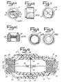
- the cable splice protector of this invention comprises a first inner shell 10, a second inner shell 20, a first outer shell 30, and a second outer shell 40.
- First inner shell 10 and second inner shell 20 unite to enclose one or more cable splice.
- First outer shell 30 and second outer shell 40 unite to form a recess that covers first and second inner shells 10 and 20 and that compressively isolates each cable splice from dirt and moisture.
- first inner shell 10 is preferably cylindrical in shape and has a first open end 12 and a second open end 14. Second open end 14 will generally have a smaller cross-sectional area than first open end 12.
- First inner shell 10 also includes a compressible wall 19.
- Compressible wall 19 forms second open end 14 of first inner shell 10.
- Compressible wall 19 may be any type of structure that is capable of being radially compressed. Examples of compressible walls include a radially corrugated wall, an iris type device that operates similarly to a camera aperture, or any other structure that is radially compressible.
- the preferred compressible wall 19 is made up of a plurality of columns 18. The walls of each column 18 are tapered slightly to allow columns 18 to be uniformly compressed.
- First inner shell 10 includes an apertured grommet 15.
- Apertured grommet 15 is located inside compressible wall 19 of first inner shell 10. It is preferred that first inner shell 10 has a ledge 16 located on the inner dimension of the first inner shell 10 in the area where compressible wall 19 is associated with the non-compressible wall portion of first inner shell 10.
- Apertured grommet 15 is preferably located in first inner shell 10 such that apertured grommet 15 rests on ledge 16 and extends up to and optionally beyond first open end 12. It is preferred that the diameter of apertured grommet 15 is large enough to slightly distend compressible wall 19 when it is associated with first inner shell 10.
- Second inner shell 20 is similar in structure to first inner shell 10.
- Second inner shell 20 is preferably cylindrically shaped and has a first open end 22 and a second open end 24. Second open end 24 will generally have a smaller cross-sectional area than first open end 22.
- Second inner shell 20 also includes a compressible wall 29. Compressible wall 29 is located adjacent to and forms second open end 24. Compressible wall 29 may be any type of structure that is capable of being radially compressed. Examples of compressible walls include a radially corrugated wall, an iris type device that operates similarly to a camera aperture or any other element that is radially compressible.
- a preferred compressible wall 29 is made up of a plurality of columns 18. The walls of each column are tapered slightly to allow columns 18 to be compressed.
- Second inner shell 20 includes a apertured grommet 25.
- Apertured grommet 25 is located inside the portion of second inner shell 20 that is defined by compressible wall 29. It is preferred that second inner shell 20 includes a ledge 26. Ledge 26 is located on the inner dimension of second inner shell 26 in the area where compressible wall 29 is associated with a non-compressible wall portion of first inner shell 20.
- Apertured grommet 25 is associated with second inner shell 20 such that apertured grommet 25 rests on ledge 26 and extends at least up to, and optionally beyond the second open end 24. It is preferred that apertured grommet 25 has a diameter slightly larger than second open end 24 so that compressible wall 29 distends slightly when apertured grommet 25 is associated with second inner shell 20.
- First open end 12 and first open end 22 are complementary to one another.
- the openings may be complementary by virtue of having the same dimension or the openings may include complementary connectors. It is preferred that first open end 12 and first open end 22 have the same dimensions.
- First inner shell 10 and second inner shell 20 are sealed where they meet at first open end 12 and first open end 22.
- the seal can take the form of a gasket, sealing tape such as teflon tape, an adhesive seal, an O-ring, a sealable connector, or any other method known that is capable of sealing a threaded or non-threaded union.
- first inner shell 10 and second inner shell 20 is an O-ring 50.
- O-ring 50 is located in a recess 17 that passes continuously around the face of either first open end 12 or 22.
- Figures 2A and 2B show recess 17 associated with face 11 of first inner shell 10.
- Recess 17 should be deep enough to hold O-ring 50, but shallow enough to allow a portion of O-ring 50 to extend above face 11 of first open end 12.
- recess 17 includes one or more retaining walls 53. Retaining walls 53 hold O-ring 50 in recess 17.
- the apertured grommets 15 and 25 of this invention include one or more apertures that pass entirely through apertured grommet 15 or 25.
- the number, shape and size of the apertures associated with aperture grommets 15 and 25 will depend upon the number, type, and size of the cables being spliced. It is conceivable that apertured grommet 15 associated with first inner shell 10 will have more apertures or apertures of a different size in comparison to apertured grommet 25 associated with second inner shell 20. As shown in Figures 7, 8 and 9, the apertures may vary in diameter, in number or, as shown in Figure 6A, in shape.
- a first connector 35 is associated with first outer shell 30 in the proximity of first open end 32.
- First connector 35 is complementary to a second connector 46 associated with second outer shell 40.
- Second open end 33 includes a tapered shoulder 36 which tapers inwardly towards second open end 33.
- the cable splice protector of this invention also includes a second outer shell 40.
- Second outer shell 40 is similar in construction to first outer shell 30.
- Second outer shell 40 is preferably cylindrical in shape having first open end 41 and second open end 43, the combination defining a cavity 42 which is capable of completely containing second inner shell 20.
- Second open end 43 preferably has a smaller cross-sectional area than first open end 41.
- second open end 43 includes a tapered shoulder 45 which tapers inwardly towards second open end 43.
- Second outer shell 40 includes a second connector 46.
- First connector 35 and second connector 44 are complementary and act to draw first outer shell 30 and second outer shell 40 together. Examples of such a connector would include complementary threaded connectors or a ratchet, pawl combination. It is preferred that first connector 35 is a threaded connector associated with the outer dimension of first outer shell 30 and second connector 46 is a complementary threaded connector associated with the inner dimension of second outer shell 40.
- Second outer shell 40 may include one or more locking slots 48 associated with inner dimension 45 of second outer shell 40.
- Each locking slot 48 is complementary to a guide arm 27 associated with the outer dimension of second inner shell 20. It is preferred that second inner shell 20 is centrally located in second outer shell 40. This central location is achieved by locating a guide arm 27 in each locking slot 48. Guide arm 27 controls the distance between second inner shell 20 and second outer shell 40 thereby centrally positioning second inner shell 20 in second outer shell 40.
- First inner shell 10 is intended to fit into cavity 31 of first outer shell 30.
- First inner shell 10 is preferably centered in first outer shell 30.
- the centering is preferably achieved by sizing first inner shell 10 so that it can be press fit into cavity 31.
- the press fitting prevents first inner shell 10 from moving laterally in first outer shell 30.
- the cable splice protector includes a first outer shell 30.
- First outer shell 30 is preferably cylindrical in shape and includes a first open end 32 and a second open end 33.
- the combination forms cavity 31 that is capable of completely containing first inner shell 10.
- First open end 32 preferably has a larger cross-sectional area than second open end 33.
- the cable shield protector of this invention is intended to be associated with one or more cable splices.
- the various parts In order to associate the cable splice protector of this invention with a cable splice, the various parts must be associated with at least a first cable end 55 and with a second cable end 56 before the first and second cable ends are spliced.
- the method for associating the various parts of the cable splice protector with the first and second cable end may vary. For example, in one method, portions of the cable splice protector may be preassembled and then associated with one or more cable ends. Alternatively, the various elements of the cable splice protector may be associated with the two wire ends and then assembled around one or more cable splices.
- apertured grommet 15 is associated with first inner shell 10 so that apertured grommet 15 is located inside compressible wall 19 and abuts ledge 16.
- first inner shell 10 is centrally located in first outer shell 30.
- the combination of grommet 15, first inner shell 10, and first outer shell 30 is referred to as the first cable splice sub-assembly.
- a second cable splice sub-assembly comprising apertured grommet 25, second inner shell 20 and second outer shell 40 is assembled by pushing apertured grommet 25 inside compressible wall 29 of second inner shell 20 until apertured grommet 25 abuts ledge 26 of second inner shell 20.
- Second inner shell 20 is then centrally located in cavity 47 of second outer shell 40.
- Second inner shell 20 is associated with second outer shell 40 so that second open end 24 of second inner shell 20 is complementary to second open end 43 of second outer shell 40.
- first open end 22 of second inner shell 20 is complementary to first open end 32 of first outer shell 30.
- second inner shell 20 includes one or more guide arms 27 complementary to locking slots 48 and second outer shell 40.
- the combination of the guidearms 27 and locking slots 48 centers second inner shell 20 in second outer shell 40.
- first inner shell 10 is press fit into cavity 31 of first outer shell 30.
- first cable splice sub-assembly and second cable splice sub-assembly are now associated with end 55 and 566 of a first cable 57 second cable 58 respectively.
- End 55 of first cable 57 is associated with first cable splice sub-assembly by passing end 55 through an aperture 13 of apertured grommet 15.
- the end of the first cable is then passed through first grommet 15, through first inner shell 10, and first outer shell 30 and out of first open end 12 of first inner shell 10 and first open end 32 of first outer shell 30.
- the second cable end is associated with the second cable protector subassembly in essentially the same manner.
- first cable protector sub-assembly with second cable protector sub-assembly. This is achieved by moving first cable protector sub-assembly towards second cable protector sub-assembly until first open end 32 and second open 42 are complementary to one another.
- first connector 35 of first outer shell 30 is engaged with second connector 46 associated with second outer shell 40 to compressively seal and protect the cable splice.
- first and second cable splice protector sub-assemblies Uniting the first and second cable splice protector sub-assemblies causes the cable splice to be sealed from dirt and moisture using at least two different compressive seals.
- first open end 12 of first inner shell 10 and first open end 22 of second inner shell 20 abut one another.
- first open end 12 of first inner shell 10 and first open end 22 of second inner shell 20 abut one another.
- compressible wall 19 and 29 against tapered shoulder 45 of second outer shell 40 Compressing compressible walls 19 and 29 against tapered shoulders 36 and 45 causes compressible wall to radially compress against apertured grommets 15 and 25 respectively.
- lateral compression caused by connecting the two sub-assemblies forces apertured grommet 15 to seal against ledge 16 and forces apertured grommet 25 to seal against ledge 26.
- the radial compression of compressible walls 19 and 29 uniformly compresses apertured grommets 15 and 25 respectively causing the soft grommet material to uniformly compress around the cable or cables being spliced.
- the lateral and radial compression combine to isolate the cable splice site 57 or splice sites from contaminants.
- the cable splice protector includes a third, preferred compressible seal.
- first inner shell 10 includes a recess 17 in which O-ring 50 is located.
- the recess 17 includes a plurality of O-ring retaining walls 53 which grasp and partially retain O-ring 50 in circular depression 17.
- first cable shield sub-assembly is united with the second sub-assembly, first open end 12 of first inner shell 10 abuts second first open end 22 of second inner shell 20. Compression caused by connecting first and second cable shield sub-assemblies causes O-ring 50 to become compressed between first open end 12 and second open end 22 thereby sealing the radial location where first inner shell 10 abuts second inner shell 20.
- First outer shell 30 and second outer shell 40 preferably include holes 54. Holes 54 allow any water that becomes trapped in the area between the inner shells and the outer shells to drain out of cavities 31 and 42.
- apertures 13 and 23 associated with first grommet 15 and second grommet 25 include one or more scales 51 as shown in Figure 6C.
- Each scale 51 acts as a discrete seal around the circumference of any cable that passes through apertured grommet 15 or 25.
Landscapes
- Cable Accessories (AREA)
- Details Of Indoor Wiring (AREA)
Applications Claiming Priority (2)
| Application Number | Priority Date | Filing Date | Title |
|---|---|---|---|
| US10067293A | 1993-07-30 | 1993-07-30 | |
| US100672 | 1993-07-30 |
Publications (2)
| Publication Number | Publication Date |
|---|---|
| EP0637116A1 true EP0637116A1 (de) | 1995-02-01 |
| EP0637116B1 EP0637116B1 (de) | 1998-01-07 |
Family
ID=22280946
Family Applications (1)
| Application Number | Title | Priority Date | Filing Date |
|---|---|---|---|
| EP94305504A Expired - Lifetime EP0637116B1 (de) | 1993-07-30 | 1994-07-26 | Schutzvorrichtung für Kabelspleiss |
Country Status (5)
| Country | Link |
|---|---|
| US (1) | US5502280A (de) |
| EP (1) | EP0637116B1 (de) |
| CA (1) | CA2129153C (de) |
| DE (1) | DE69407682T2 (de) |
| ES (1) | ES2114140T3 (de) |
Cited By (9)
| Publication number | Priority date | Publication date | Assignee | Title |
|---|---|---|---|---|
| EP2437355A1 (de) * | 2010-09-29 | 2012-04-04 | John Mezzalingua Associates, Inc. | Abdeckung für Kabelstecker |
| US8419467B2 (en) | 2010-04-14 | 2013-04-16 | John Mezzalingua Associates, Inc. | Cover for cable connectors |
| US8529288B2 (en) | 2010-04-14 | 2013-09-10 | John Mezzalingua Associates, LLC | Cover for cable connectors |
| US8764480B2 (en) | 2010-04-14 | 2014-07-01 | John Mezzalingua Associates, LLP | Cover for cable connectors |
| US8853542B2 (en) | 2009-03-30 | 2014-10-07 | John Mezzalingua Associates, LLC | Collar for sealingly engaging a cover for cable connectors |
| CN104836062A (zh) * | 2015-04-14 | 2015-08-12 | 江苏赛洋机电科技有限公司 | 一种电线或电缆防水快装连接器 |
| USD744071S1 (en) | 2009-03-30 | 2015-11-24 | John Mezzalingua Associates, LLC | Connector covering device |
| FR3032836A1 (fr) * | 2015-02-16 | 2016-08-19 | Alstom Technology Ltd | Sous ensemble compose de deux conducteurs cylindriques et d'un manchon de raccordement en deux parties |
| EP4054016A1 (de) * | 2021-03-05 | 2022-09-07 | Aptiv Technologies Limited | Elektrischer verbinder mit zugentlastung und abdichtung |
Families Citing this family (35)
| Publication number | Priority date | Publication date | Assignee | Title |
|---|---|---|---|---|
| US5760332A (en) * | 1993-07-30 | 1998-06-02 | Etcon Corporation | Cable splice protector |
| US6069320A (en) * | 1993-07-30 | 2000-05-30 | Etcon Corporation | Cable splice protector |
| US6036526A (en) * | 1996-12-13 | 2000-03-14 | Alfis, Iii; Michael V. | Sealable enclosure for electrical cable connectors |
| US5821461A (en) * | 1997-05-20 | 1998-10-13 | Shaw Industries Limited | Waterproof splice for cables having different insulation materials and method of making same |
| US6007356A (en) * | 1998-07-02 | 1999-12-28 | Stein; Myron | Water tight quick connect electrical connector |
| US6036525A (en) * | 1998-11-02 | 2000-03-14 | Alfis, Iii; Michael V. | Sealable enclosure for electrical cable connectors |
| US6692313B1 (en) | 1999-08-02 | 2004-02-17 | Swenco Products, Inc. | No-crimp electrical connector side-by-side type |
| US6494753B1 (en) | 1999-08-02 | 2002-12-17 | Swenco Products, Inc. | No-crimp electrical connector side-by-side type and method |
| US6358103B1 (en) | 1999-08-02 | 2002-03-19 | Swenco Products, Inc. | No-crimp electrical connector side-by-side type |
| US6284977B1 (en) * | 2000-01-31 | 2001-09-04 | General Electric Company | Splice connector and method of using the same |
| FR2805589B1 (fr) * | 2000-05-18 | 2002-07-05 | Jean Claude Roue | Dispositif d'enveloppement pour element de ligne filaire |
| EP1313351A1 (de) * | 2001-11-16 | 2003-05-21 | Thermon Europe B.V. | Verbindungsmuffe für Heizleiter |
| US7339115B2 (en) * | 2005-07-15 | 2008-03-04 | Rockbestos Surprenant Cable Corp | Fire resistant electrical cable splice |
| US7214095B1 (en) * | 2005-10-19 | 2007-05-08 | John Mezzalingua Associates, Inc. | Sealing security shield |
| KR100984781B1 (ko) * | 2008-04-08 | 2010-10-04 | 이용우 | 전동식 클립 자동 사출기 |
| GB2478894B (en) * | 2009-01-21 | 2014-03-05 | Farrel Roy Brenner | Improvements in and relating to electrical connector housings |
| US7838775B2 (en) | 2009-03-30 | 2010-11-23 | John Mezzalingua Associates, Inc. | Cover for cable connectors |
| US20120214335A1 (en) * | 2009-03-30 | 2012-08-23 | John Mezzalingua Associates, Inc. | Cover for cable connectors |
| USD646227S1 (en) | 2010-09-17 | 2011-10-04 | John Mezzalingua Associates, Inc. | Sealing boot |
| BR112013008105A2 (pt) | 2010-09-21 | 2016-08-09 | Huber+Suhner Ag | montagens de rompimento de cabo vedadas ao ambiente |
| USD642539S1 (en) | 2010-10-20 | 2011-08-02 | John Mezzalingua Associates, Inc. | Weather proofing system |
| JP2012190769A (ja) * | 2011-03-10 | 2012-10-04 | Smk Corp | 車両充電ケーブル用ソケットコネクタ |
| DE102011100727B4 (de) * | 2011-05-06 | 2016-01-07 | Hoch.Rein Gmbh | Kabelverbindungsvorrichtung |
| TWM422799U (en) * | 2011-09-29 | 2012-02-11 | Delta Electronics Inc | Cable coupling protection apparatus and cable with the same |
| TWI436530B (zh) * | 2011-09-29 | 2014-05-01 | Delta Electronics Inc | 纜線對接保護裝置、具有保護裝置之纜線及其組裝方法 |
| CA2880800C (en) * | 2012-06-27 | 2021-08-10 | Quick Connectors, Inc. | Power cable splice sleeve and installation method |
| US9216530B2 (en) | 2012-10-08 | 2015-12-22 | Commscope Technologies Llc | Connector cover |
| US9616602B2 (en) | 2013-07-10 | 2017-04-11 | Commscope Technologies Llc | Interconnection seal |
| JP6117054B2 (ja) * | 2013-08-28 | 2017-04-19 | モレックス エルエルシー | コネクタ |
| USD740760S1 (en) * | 2014-08-06 | 2015-10-13 | Michael Gene Gliksman | Braided electrical speaker cable |
| US9899823B1 (en) | 2017-03-21 | 2018-02-20 | George E. Catinis | Apparatus and method for sheltering electrical cord connections |
| JP7022335B2 (ja) * | 2018-05-16 | 2022-02-18 | 住友電装株式会社 | コネクタ |
| USD911988S1 (en) | 2018-09-19 | 2021-03-02 | George E. Catinis | Shelter for electrical cord connections or the like |
| US11069997B1 (en) * | 2020-06-13 | 2021-07-20 | Glenair, Inc. | High-power electrical feeder connector |
| CN117673782A (zh) | 2022-09-08 | 2024-03-08 | 开利公司 | 线缆连接器组件和用于组装该线缆连接器组件的方法 |
Citations (6)
| Publication number | Priority date | Publication date | Assignee | Title |
|---|---|---|---|---|
| US2001131A (en) * | 1933-01-10 | 1935-05-14 | Henry C Guhl | Solderless connecter for electric conducting cables |
| US2239026A (en) * | 1939-12-06 | 1941-04-22 | Henry J Wagner | Cable connector |
| NL50529C (de) * | 1938-09-07 | 1941-06-16 | ||
| DE1939312A1 (de) * | 1968-08-01 | 1970-02-05 | Amp Inc | Isolierschutzkappen fuer elektrische Verbindungsanordnungen |
| GB2140985A (en) * | 1983-05-30 | 1984-12-05 | Pirelli Treficable | Joint between underground and overhead low-tension cables |
| EP0225784A2 (de) * | 1985-12-09 | 1987-06-16 | Amerace Corporation | Schutzvorrichtung für die Spleissstelle eines Hochspannungskabels |
Family Cites Families (28)
| Publication number | Priority date | Publication date | Assignee | Title |
|---|---|---|---|---|
| US242388A (en) * | 1881-05-31 | Orlando f | ||
| US457865A (en) * | 1891-08-18 | Joint for electric conductors | ||
| US297927A (en) * | 1884-04-29 | goebel | ||
| US706567A (en) * | 1901-06-27 | 1902-08-12 | Thomas P Jones | Telephone-cable connection. |
| US707055A (en) * | 1901-12-06 | 1902-08-12 | William J Stapleton | Cable-sleeve. |
| US743346A (en) * | 1902-11-20 | 1903-11-03 | Joseph G Swain | Electrical connector. |
| US862618A (en) * | 1904-01-19 | 1907-08-06 | Dossert & Company | Coupling for lead-covered electric cables. |
| US1167962A (en) * | 1913-12-12 | 1916-01-11 | Wilbur O Wilson | Cable-splice. |
| US1688640A (en) * | 1921-04-19 | 1928-10-23 | Jeffrey Mfg Co | Terminal connecting device |
| US1656912A (en) * | 1923-09-03 | 1928-01-24 | Foster Charles Edwin | Double-pole electrical connecter |
| US1718817A (en) * | 1925-04-01 | 1929-06-25 | Condit Electrical Mfg Corp | Cable connecter |
| US1975244A (en) * | 1932-07-08 | 1934-10-02 | United Dry Docks Inc | Joint for electrical conductors |
| US2478082A (en) * | 1945-10-24 | 1949-08-02 | Aircraft Marine Prod Inc | Electrical connector |
| US3041575A (en) * | 1960-08-31 | 1962-06-26 | Wilhelm A Schneider | Connecting means |
| FR1278132A (fr) * | 1960-10-27 | 1961-12-08 | Raccord pour câbles électriques | |
| US3187088A (en) * | 1962-11-01 | 1965-06-01 | Minerallac Electric Company | High voltage cable splice |
| US3290064A (en) * | 1963-08-08 | 1966-12-06 | Edwin H Bush | Cable coupling shield |
| US3381082A (en) * | 1965-11-15 | 1968-04-30 | Comm Equipment And Engineering | Cable splicers and the like |
| FR1490745A (fr) * | 1966-06-24 | 1967-08-04 | British Indulated Callender S | Raccordements et fins de câble perfectionnés pour câbles électriques |
| US3573346A (en) * | 1969-07-24 | 1971-04-06 | Preformed Line Products Co | Strain relief coupling |
| FR2219553B1 (de) * | 1973-02-26 | 1977-07-29 | Cables De Lyon Geoffroy Delore | |
| US4029895A (en) * | 1976-10-12 | 1977-06-14 | Amp Incorporated | Re-enterable splice case |
| US4192964A (en) * | 1978-05-11 | 1980-03-11 | Burndy Corporation | Modifiable stop element for cable connector assemblies |
| DE3041657A1 (de) * | 1980-11-05 | 1982-06-03 | HEW-Kabel Heinz Eilentropp KG, 5272 Wipperfürth | Verfahren und vorrichtung zur herstellung zugfester und druckdichter, insbesondere temperaturbestaendiger, verbindungen fuer elektrische kabel und leitungen |
| DE3329904A1 (de) * | 1983-08-18 | 1985-03-07 | Siemens AG, 1000 Berlin und 8000 München | Kabelmuffe fuer abzweiger- und verteilergehaeuse |
| FR2553594B1 (fr) * | 1983-10-14 | 1986-02-21 | Auxiliaire Appar Electric | Connecteur pour cables electriques isoles |
| JPH03198615A (ja) * | 1989-12-27 | 1991-08-29 | Furukawa Electric Co Ltd:The | 電力ケーブル接続箱の導体移動量検出装置 |
| JP2875035B2 (ja) * | 1991-02-12 | 1999-03-24 | 株式会社フジクラ | 防水コネクタ |
-
1994
- 1994-07-26 DE DE69407682T patent/DE69407682T2/de not_active Expired - Fee Related
- 1994-07-26 EP EP94305504A patent/EP0637116B1/de not_active Expired - Lifetime
- 1994-07-26 ES ES94305504T patent/ES2114140T3/es not_active Expired - Lifetime
- 1994-07-29 CA CA002129153A patent/CA2129153C/en not_active Expired - Fee Related
- 1994-11-07 US US08/335,111 patent/US5502280A/en not_active Expired - Lifetime
Patent Citations (6)
| Publication number | Priority date | Publication date | Assignee | Title |
|---|---|---|---|---|
| US2001131A (en) * | 1933-01-10 | 1935-05-14 | Henry C Guhl | Solderless connecter for electric conducting cables |
| NL50529C (de) * | 1938-09-07 | 1941-06-16 | ||
| US2239026A (en) * | 1939-12-06 | 1941-04-22 | Henry J Wagner | Cable connector |
| DE1939312A1 (de) * | 1968-08-01 | 1970-02-05 | Amp Inc | Isolierschutzkappen fuer elektrische Verbindungsanordnungen |
| GB2140985A (en) * | 1983-05-30 | 1984-12-05 | Pirelli Treficable | Joint between underground and overhead low-tension cables |
| EP0225784A2 (de) * | 1985-12-09 | 1987-06-16 | Amerace Corporation | Schutzvorrichtung für die Spleissstelle eines Hochspannungskabels |
Cited By (14)
| Publication number | Priority date | Publication date | Assignee | Title |
|---|---|---|---|---|
| US8853542B2 (en) | 2009-03-30 | 2014-10-07 | John Mezzalingua Associates, LLC | Collar for sealingly engaging a cover for cable connectors |
| US9106003B2 (en) | 2009-03-30 | 2015-08-11 | John Mezzalingua Associates, LLC | Cover for cable connectors |
| US9130303B2 (en) | 2009-03-30 | 2015-09-08 | John Mezzalingua Associates, LLC | Cover for cable connectors |
| USD744071S1 (en) | 2009-03-30 | 2015-11-24 | John Mezzalingua Associates, LLC | Connector covering device |
| US9917394B2 (en) | 2010-04-14 | 2018-03-13 | John Mezzalingua Associates, LLC | Cable connector cover |
| US8419467B2 (en) | 2010-04-14 | 2013-04-16 | John Mezzalingua Associates, Inc. | Cover for cable connectors |
| US8529288B2 (en) | 2010-04-14 | 2013-09-10 | John Mezzalingua Associates, LLC | Cover for cable connectors |
| US8764480B2 (en) | 2010-04-14 | 2014-07-01 | John Mezzalingua Associates, LLP | Cover for cable connectors |
| US10847925B2 (en) | 2010-04-14 | 2020-11-24 | John Mezzalingua Associates, LLC | Cable connector cover |
| EP2437355A1 (de) * | 2010-09-29 | 2012-04-04 | John Mezzalingua Associates, Inc. | Abdeckung für Kabelstecker |
| FR3032836A1 (fr) * | 2015-02-16 | 2016-08-19 | Alstom Technology Ltd | Sous ensemble compose de deux conducteurs cylindriques et d'un manchon de raccordement en deux parties |
| WO2016131749A1 (fr) * | 2015-02-16 | 2016-08-25 | General Electric Technology Gmbh | Sous ensemble composé de deux conducteurs cylindriques et d'un manchon de raccordement en deux parties |
| CN104836062A (zh) * | 2015-04-14 | 2015-08-12 | 江苏赛洋机电科技有限公司 | 一种电线或电缆防水快装连接器 |
| EP4054016A1 (de) * | 2021-03-05 | 2022-09-07 | Aptiv Technologies Limited | Elektrischer verbinder mit zugentlastung und abdichtung |
Also Published As
| Publication number | Publication date |
|---|---|
| ES2114140T3 (es) | 1998-05-16 |
| CA2129153A1 (en) | 1995-01-31 |
| DE69407682D1 (de) | 1998-02-12 |
| CA2129153C (en) | 1997-11-04 |
| EP0637116B1 (de) | 1998-01-07 |
| US5502280A (en) | 1996-03-26 |
| DE69407682T2 (de) | 1998-08-06 |
Similar Documents
| Publication | Publication Date | Title |
|---|---|---|
| US5502280A (en) | Cable splice protector | |
| CA1128156A (en) | Jacketed metal clad cable connector | |
| US5064268A (en) | High pressure fiber optic connector plug | |
| US4039742A (en) | Waterproof cable splice enclosure kit | |
| US4336977A (en) | Crimped connector assembly for fiber optic cables | |
| US5432302A (en) | Hydrostatic sealing sleeve for spliced wire connections | |
| EP0225784A2 (de) | Schutzvorrichtung für die Spleissstelle eines Hochspannungskabels | |
| US5435751A (en) | Device for connecting a coaxial cable end to a contact socket | |
| US5315065A (en) | Versatile electrically insulating waterproof connectors | |
| US4241967A (en) | Electrical connector assembly sealing grommet | |
| JPH0522210B2 (de) | ||
| US6069320A (en) | Cable splice protector | |
| EP0563995A1 (de) | Optischer Faserverbinder | |
| US5470248A (en) | Field repairable electrical connector | |
| EP0730322A1 (de) | Elektrischer Unterwassersteckverbinder | |
| KR100337568B1 (ko) | 케이블밀봉장치 | |
| GB2043943A (en) | Optical cable gland | |
| JPS5812807B2 (ja) | オプチカルファイバ又は導電体等用の高圧パッキング装置 | |
| EP0008603B1 (de) | Leitungskupplung zum Durchverbinden von zwei elektrischen Leitungen | |
| US4381425A (en) | Universal joint box for telecommunication or power cables | |
| US3449507A (en) | Cable splice enclosure | |
| EP0207449A2 (de) | Schutzhülle für optische Faserkupplungen | |
| US4306760A (en) | Cable connector assembly | |
| JPH0568926B2 (de) | ||
| US6160221A (en) | Screwed cable gland for a shielded cable |
Legal Events
| Date | Code | Title | Description |
|---|---|---|---|
| PUAI | Public reference made under article 153(3) epc to a published international application that has entered the european phase |
Free format text: ORIGINAL CODE: 0009012 |
|
| AK | Designated contracting states |
Kind code of ref document: A1 Designated state(s): DE ES FR GB IT |
|
| 17P | Request for examination filed |
Effective date: 19950720 |
|
| GRAG | Despatch of communication of intention to grant |
Free format text: ORIGINAL CODE: EPIDOS AGRA |
|
| 17Q | First examination report despatched |
Effective date: 19961125 |
|
| GRAG | Despatch of communication of intention to grant |
Free format text: ORIGINAL CODE: EPIDOS AGRA |
|
| GRAH | Despatch of communication of intention to grant a patent |
Free format text: ORIGINAL CODE: EPIDOS IGRA |
|
| GRAH | Despatch of communication of intention to grant a patent |
Free format text: ORIGINAL CODE: EPIDOS IGRA |
|
| GRAA | (expected) grant |
Free format text: ORIGINAL CODE: 0009210 |
|
| AK | Designated contracting states |
Kind code of ref document: B1 Designated state(s): DE ES FR GB IT |
|
| REF | Corresponds to: |
Ref document number: 69407682 Country of ref document: DE Date of ref document: 19980212 |
|
| ITF | It: translation for a ep patent filed | ||
| ET | Fr: translation filed | ||
| REG | Reference to a national code |
Ref country code: ES Ref legal event code: FG2A Ref document number: 2114140 Country of ref document: ES Kind code of ref document: T3 |
|
| PLBE | No opposition filed within time limit |
Free format text: ORIGINAL CODE: 0009261 |
|
| STAA | Information on the status of an ep patent application or granted ep patent |
Free format text: STATUS: NO OPPOSITION FILED WITHIN TIME LIMIT |
|
| 26N | No opposition filed | ||
| PGFP | Annual fee paid to national office [announced via postgrant information from national office to epo] |
Ref country code: GB Payment date: 19990721 Year of fee payment: 6 |
|
| PGFP | Annual fee paid to national office [announced via postgrant information from national office to epo] |
Ref country code: ES Payment date: 19990723 Year of fee payment: 6 Ref country code: DE Payment date: 19990723 Year of fee payment: 6 |
|
| PGFP | Annual fee paid to national office [announced via postgrant information from national office to epo] |
Ref country code: FR Payment date: 19990726 Year of fee payment: 6 |
|
| PG25 | Lapsed in a contracting state [announced via postgrant information from national office to epo] |
Ref country code: GB Free format text: LAPSE BECAUSE OF NON-PAYMENT OF DUE FEES Effective date: 20000726 |
|
| PG25 | Lapsed in a contracting state [announced via postgrant information from national office to epo] |
Ref country code: ES Free format text: LAPSE BECAUSE OF NON-PAYMENT OF DUE FEES Effective date: 20000727 |
|
| GBPC | Gb: european patent ceased through non-payment of renewal fee |
Effective date: 20000726 |
|
| PG25 | Lapsed in a contracting state [announced via postgrant information from national office to epo] |
Ref country code: FR Free format text: LAPSE BECAUSE OF NON-PAYMENT OF DUE FEES Effective date: 20010330 |
|
| REG | Reference to a national code |
Ref country code: FR Ref legal event code: ST |
|
| PG25 | Lapsed in a contracting state [announced via postgrant information from national office to epo] |
Ref country code: DE Free format text: LAPSE BECAUSE OF NON-PAYMENT OF DUE FEES Effective date: 20010501 |
|
| REG | Reference to a national code |
Ref country code: ES Ref legal event code: FD2A Effective date: 20010810 |
|
| PG25 | Lapsed in a contracting state [announced via postgrant information from national office to epo] |
Ref country code: IT Free format text: LAPSE BECAUSE OF NON-PAYMENT OF DUE FEES;WARNING: LAPSES OF ITALIAN PATENTS WITH EFFECTIVE DATE BEFORE 2007 MAY HAVE OCCURRED AT ANY TIME BEFORE 2007. THE CORRECT EFFECTIVE DATE MAY BE DIFFERENT FROM THE ONE RECORDED. Effective date: 20050726 |