EP2437355A1 - Abdeckung für Kabelstecker - Google Patents
Abdeckung für Kabelstecker Download PDFInfo
- Publication number
- EP2437355A1 EP2437355A1 EP10182355A EP10182355A EP2437355A1 EP 2437355 A1 EP2437355 A1 EP 2437355A1 EP 10182355 A EP10182355 A EP 10182355A EP 10182355 A EP10182355 A EP 10182355A EP 2437355 A1 EP2437355 A1 EP 2437355A1
- Authority
- EP
- European Patent Office
- Prior art keywords
- cover
- connector
- cable
- region
- elongated body
- Prior art date
- Legal status (The legal status is an assumption and is not a legal conclusion. Google has not performed a legal analysis and makes no representation as to the accuracy of the status listed.)
- Withdrawn
Links
Images


Classifications
-
- H—ELECTRICITY
- H01—ELECTRIC ELEMENTS
- H01R—ELECTRICALLY-CONDUCTIVE CONNECTIONS; STRUCTURAL ASSOCIATIONS OF A PLURALITY OF MUTUALLY-INSULATED ELECTRICAL CONNECTING ELEMENTS; COUPLING DEVICES; CURRENT COLLECTORS
- H01R13/00—Details of coupling devices of the kinds covered by groups H01R12/70 or H01R24/00 - H01R33/00
- H01R13/46—Bases; Cases
- H01R13/52—Dustproof, splashproof, drip-proof, waterproof, or flameproof cases
- H01R13/5213—Covers
-
- H—ELECTRICITY
- H01—ELECTRIC ELEMENTS
- H01R—ELECTRICALLY-CONDUCTIVE CONNECTIONS; STRUCTURAL ASSOCIATIONS OF A PLURALITY OF MUTUALLY-INSULATED ELECTRICAL CONNECTING ELEMENTS; COUPLING DEVICES; CURRENT COLLECTORS
- H01R4/00—Electrically-conductive connections between two or more conductive members in direct contact, i.e. touching one another; Means for effecting or maintaining such contact; Electrically-conductive connections having two or more spaced connecting locations for conductors and using contact members penetrating insulation
- H01R4/70—Insulation of connections
Definitions
- Cell towers contain antennas, transceivers and other wireless signal receiving apparatus mounted thereon from which a cable accepts and distributes the signal to a predetermined destination.
- Cell towers may be free-standing or mounted to a roof, pole, or other structure. Regardless, the cell towers and components mounted thereon are open to the environment and thus susceptible to degradation from weather related corrosive effects (e.g., moisture infiltration), pollution, debris and other elements. Degradation of the components potentially leads to degradation of the signal quality being transmitted through the cables that carry the wirelessly received signals at the cell tower.
- plastic clamshell or valise type covers have been used to envelop the components.
- These style covers are exemplified by the plastic material composition and the closure mechanisms used to open and close them around the components. While the opening and closing of the clamshell style cover facilitates quicker installation and removal in repair situations, it too is not without its drawbacks. For instance, the plastic material becomes brittle in colder temperatures, and this reduction in ductility increases over time. As the material becomes more brittle, the closure mechanisms lose their effectiveness often breaking or otherwise not reliably performing the closure function for which they were designed.
- the clamshell style closures include seams that extend essentially the entire periphery of the cover, making the sealing function much more difficult when compared to covers that do not include such long seams between parts. As such, the clamshell style covers lose their sealing effectiveness over time and in climates that routinely experience cold temperatures.
- a first aspect of the present invention provides a cover for a connector adapted to terminate a cable, wherein the connector includes a body portion and a coupler element.
- the cover essentially comprises an elongated body member extending along a longitudinal axis and having cable and bulkhead ends, and interior and exterior surfaces; a plurality of spaced apart grooves formed in a predetermined region of the interior surface of the body member, proximate the cable end; wherein the interior surface of the body member is adapted to sealingly envelop the connector.
- a second aspect of the present invention provides a cover for a connector adapted to terminate a signal carrying cable, wherein the connector includes a body portion and a coupling element and is adapted to terminate in a bulkhead with a shank portion extending outwardly therefrom.
- the cover comprises an elongated body member having proximal and distal ends, interior and exterior surfaces, and extends along a longitudinal axis.
- the interior surface of the cover includes a first region adapted to cover at least a portion of the signal carrying cable and extending from the proximal end to a first shoulder, the first region being of a minimum, first cross-sectional diameter, a medial region adapted to cover at least the connector body portion and nut and that extends from the first shoulder to a second shoulder, the second region being of a minimum, second cross-sectional diameter that is greater than the minimum, first cross-sectional diameter, and a third region adapted to cover the shank portion and that extends from the second shoulder to the distal end, the third region being of a minimum, third cross-sectional diameter that is greater than the minimum, second cross-sectional diameter.
- the cover is composed of a rubber material, preferably a silicone rubber.
- the first region of the cover's interior surface includes a plurality of grooves formed therein, wherein each of the grooves extends in spaced parallel relation to the others, the grooves serving primarily as reservoirs for any moisture that may migrate into the cover.
- the exterior surface of the cover includes at least one wing formed on the exterior surface that serves as a gripping surface for a tool or manual engagement (e.g., fingers) used to remove the cover from a connector by axial sliding of the cover.
- a third aspect of the present invention provides a cover for a connector adapted to terminate a cable, wherein the connector includes a body portion and a coupling element (e.g., a nut), and is adapted to terminate in a bulkhead that includes a shank portion extending outwardly therefrom.
- the cover essentially comprises an elongated body member that extends along a longitudinal axis and includes cable and bulkhead ends, and interior and exterior surfaces.
- the interior surface includes a first region adapted to cover at least a portion of the signal carrying cable and extends from the cable end to a first shoulder, with the first region being of a minimum, first cross-sectional diameter; a second region adapted to cover at least the connector body portion and extend from the first shoulder to a second shoulder, with the second region being of an minimum, second cross-sectional diameter that is greater than the minimum, first cross-sectional diameter; a third region adapted to cover at least the nut and extend from the second shoulder to a third shoulder, with the third region being of a minimum, third cross-sectional diameter that is larger than the second cross-sectional diameter; and a fourth region adapted to cover the shank portion and that extend from the third shoulder to the bulkhead end, with the fourth region being of a minimum, fourth cross-sectional diameter that is greater than said minimum, third cross-sectional diameter.
- the cover further comprises a ring formed on the exterior surface that extends in a plane that is transverse to the longitudinal axis.
- a fourth aspect of the present invention provides a system for covering a first connector adapted to terminate a first cable, and further covering a second connector adapted to terminate a second cable.
- the system of covers essentially comprises a first elongated body member extending along a longitudinal axis and comprising cable and splice ends, interior and exterior surfaces, and adapted to envelop at least a portion of the first connector; a second elongated body adapted to telescopically engage the first elongated body member in enveloping relation to the second connector.
- the second elongated body member adapted to envelop the second connector comprises cable and splice ends, interior and exterior surfaces, and extends co-axially from the first body member when engaged therewith, and further comprises an annular flange that extends about said exterior surface thereof, an upper segment that extends upwardly from said annular flange and a lower segment that extends downwardly from said annular flange.
- a portion of the upper segment of the first elongated body is adapted to be positioned between the interior surface of the first elongated body member and the first connector.
- FIG. 1 a cover, designated generally by reference numeral 10, adapted to be placed in secure and sealing relation over a connector 12, such as (a 5-series connector manufactured by John Mezzalingua Associates, Inc. of East Syracuse, New York that is adapted to terminate a 7/8" cable).
- Connector 12 terminates on a bulkhead 13.
- cover 10 comprises an elongated body composed of a rubber material that exhibits a low modulus of elasticity over an extended temperature range, preferably a silicone rubber, that extends along a longitudinal axis X-X, a cable end 14, bulkhead end 16, exterior surface 18, interior surface 20, and wedge shaped wings 22 extending from opposing sides of exterior surface 18 that provide a gripping surface for a tool or manual engagement, such as pliers or a user's fingers, used to remove cover from covering relation to connector 12.
- the rubber composition of the cover permit it to elastically deform to the connector and other elements that it covers (e.g., the bulkhead), as will be described in greater detail hereinafter, when being installed or removed.
- connector 12 extends outwardly from bulkhead 13 along axis X-X.
- Bulkhead 13 includes a shank portion 28 that is either integral therewith or comprised of a separate element preferably composed of rubber. If shank portion 28 is integral with bulkhead 13, a rubber gasket 26 is preferably placed in sealing relation at the interface of shank portion 28 and the neck 29 of bulkhead 13.
- Shank portion 28 is of a diameter having a dimension at least as large as, and preferably larger than the maximum width of coupling element/nut 30 (which is the next widest part of the connector), thus creating the connector's maximum width dimension at the interface of connector 12 and bulkhead 13.
- the interior surface 20 of cover 10 includes a first region 32 that is of an essentially constant cross-sectional diameter and extends from cable end 14 to a first shoulder 34 from which it then tapers uniformly (although a stepped shoulder could apply equally) increasing the interior diameter to a second (medial) region 36 of interior surface 20 where it again remains essentially constant for a predetermined length.
- Second region 36 tapers outwardly (although it could be stepped instead of tapered) at a second shoulder 38 to a third region 40 that extends at a uniform cross-sectional diameter for the remainder of the cover's length until terminating at bulkhead end 16.
- cover 10 To use cover 10, the cover would first be fully slid (cable end 14 first) over a cable 41 that is to be terminated in connector 12, leaving the terminal end of cable 41 exposed.
- the grooves 24 in first region 32 function as small reservoirs.
- Medial region 36 extends in tightly covering relation to the majority of connector 12, including its coupling element/nut 30 (although illustrated as a nut, various types of coupling elements are conventionally used on cable connectors of the type herein described) and the interface ring 44 that interfaces connector 12 with bulkhead 13, with a seal being formed at the junction of the interface ring 44 and medial region 36.
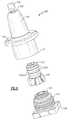
- cover 100 is adapted for placement in secure and sealed covering relation over a connector 102, such as a series 4 connector, manufactured and sold by John Mezzalingua, Associates, Inc. that is for use with a smaller cable (e.g., 1 ⁇ 2") than is connector 12.
- a connector 102 such as a series 4 connector, manufactured and sold by John Mezzalingua, Associates, Inc. that is for use with a smaller cable (e.g., 1 ⁇ 2") than is connector 12.
- cover 100 is adapted to envelop a connector that terminates in a bulkhead 104.
- the interior surface 112 of cover 100 includes a first region 116 of an essentially constant diameter that extends from cable end 106 to a first shoulder 115 from which it steps outwardly to an increased cross-sectional diameter that extends essentially uniformly in a second or medial region 118.
- the portion of connector 102 that second region 118 is adapted to cover comprises different diameter rings 120a and 120b with 120a being of slightly smaller diameter than 120b.
- the diameter of second region 118 approximates that of rings 120a and the pliable nature of cover 100 permits the material to deform to accommodate the relevant portion of connector 102 and consequently securely envelop the larger diameter rings 120b, creating tight seals at the transitions between rings 120a and 120b.
- cover 100 includes a ring 130 that extends around exterior surface 107 in a plane that is essentially transverse to the longitudinal axis Y-Y of cover 100 and is positioned at about the midpoint along the length of cover 100.
- Ring 130 serves principally as a drip edge to direct any rain water or other moisture away from the interfaces between the cover and the connector/cable. Ring 130 could also serve to provide a gripping surface for a tool used to remove cover 100 from connector 102.
- System 300 illustrated in Figures 11 - 14 , comprises a cover 400 that is adapted to cover a connector 402 (such as a series 7 connector manufactured by John Mezzalingua Associates, Inc.) in which a cable 404 (e.g., a 1 5 ⁇ 8" cable) may be terminated, and cover 100' that provides, as previously described, cover for connector 102' that in this embodiment is adapted to be spliced to connector 402.
- cover 400 it comprises cable and splice ends 405, 406, respectively, and interior and exterior surfaces 408, 410, respectively.
- a series of grooves 412 are formed in interior surface 408 in parallel spaced relation to one another in the first region 413 of cover 400 that extends from cable end 408 to a first shoulder 414. Grooves 412, like the other grooves described herein, serve as reservoirs for any moisture that migrate into cover 400 at its interface with cable 404.
Landscapes
- Connector Housings Or Holding Contact Members (AREA)
Priority Applications (1)
| Application Number | Priority Date | Filing Date | Title |
|---|---|---|---|
| EP10182355A EP2437355A1 (de) | 2010-09-29 | 2010-09-29 | Abdeckung für Kabelstecker |
Applications Claiming Priority (1)
| Application Number | Priority Date | Filing Date | Title |
|---|---|---|---|
| EP10182355A EP2437355A1 (de) | 2010-09-29 | 2010-09-29 | Abdeckung für Kabelstecker |
Publications (1)
| Publication Number | Publication Date |
|---|---|
| EP2437355A1 true EP2437355A1 (de) | 2012-04-04 |
Family
ID=43086923
Family Applications (1)
| Application Number | Title | Priority Date | Filing Date |
|---|---|---|---|
| EP10182355A Withdrawn EP2437355A1 (de) | 2010-09-29 | 2010-09-29 | Abdeckung für Kabelstecker |
Country Status (1)
| Country | Link |
|---|---|
| EP (1) | EP2437355A1 (de) |
Cited By (3)
| Publication number | Priority date | Publication date | Assignee | Title |
|---|---|---|---|---|
| DE102012216383A1 (de) * | 2012-09-14 | 2014-03-20 | Phoenix Contact Gmbh & Co. Kg | Hülsendichtung |
| EP3419106A1 (de) * | 2017-06-21 | 2018-12-26 | Alcatel-Lucent Shanghai Bell Co., Ltd. | Funkfrequenzantenne und zugehörige steckeranordnung |
| FR3102011A1 (fr) * | 2019-10-11 | 2021-04-16 | Psa Automobiles Sa | Capuchon d'etancheite pour une zone de connexion entre deux connecteurs electriques |
Citations (12)
| Publication number | Priority date | Publication date | Assignee | Title |
|---|---|---|---|---|
| US3753192A (en) * | 1969-02-04 | 1973-08-14 | Mcgrow Edison Co | Protector for electric circuits |
| GB2019665A (en) * | 1978-04-20 | 1979-10-31 | Bunker Ramo | Watertight coaxial cable connector |
| US4614392A (en) * | 1985-01-15 | 1986-09-30 | Moore Boyd B | Well bore electric pump power cable connector for multiple individual, insulated conductors of a pump power cable |
| US4915990A (en) * | 1987-03-02 | 1990-04-10 | Raychem Corporation | Method of, and elastomeric composition for, protecting a substrate |
| US5132495A (en) * | 1991-01-23 | 1992-07-21 | Homac Mfg. Company | Submersible splice cover with resilient corrugated and sections |
| EP0637116A1 (de) * | 1993-07-30 | 1995-02-01 | Etcon Corporation | Schutzvorrichtung für Kabelspleiss |
| EP0872915A2 (de) * | 1997-04-18 | 1998-10-21 | Sumitomo Wiring Systems, Ltd. | Hülle für einen elektrischen Steckverbinder |
| US5886294A (en) * | 1995-05-30 | 1999-03-23 | Scrimpshire; James Michael | Interference suppressing cable boot assembly |
| US6305945B1 (en) * | 2000-08-11 | 2001-10-23 | Kenneth M. Vance | Multiple power adapter interface apparatus |
| EP1249897A1 (de) * | 2001-04-09 | 2002-10-16 | BARTEC Componenten und Systeme GmbH | Steckverbindung |
| US20040245730A1 (en) * | 2003-06-06 | 2004-12-09 | Michael Holland | Moisture seal for an F-Type connector |
| US20060286862A1 (en) * | 2004-12-30 | 2006-12-21 | Homac Mfg. Company | Reusable insulating and sealing structure including tethered cap and associated methods |
-
2010
- 2010-09-29 EP EP10182355A patent/EP2437355A1/de not_active Withdrawn
Patent Citations (12)
| Publication number | Priority date | Publication date | Assignee | Title |
|---|---|---|---|---|
| US3753192A (en) * | 1969-02-04 | 1973-08-14 | Mcgrow Edison Co | Protector for electric circuits |
| GB2019665A (en) * | 1978-04-20 | 1979-10-31 | Bunker Ramo | Watertight coaxial cable connector |
| US4614392A (en) * | 1985-01-15 | 1986-09-30 | Moore Boyd B | Well bore electric pump power cable connector for multiple individual, insulated conductors of a pump power cable |
| US4915990A (en) * | 1987-03-02 | 1990-04-10 | Raychem Corporation | Method of, and elastomeric composition for, protecting a substrate |
| US5132495A (en) * | 1991-01-23 | 1992-07-21 | Homac Mfg. Company | Submersible splice cover with resilient corrugated and sections |
| EP0637116A1 (de) * | 1993-07-30 | 1995-02-01 | Etcon Corporation | Schutzvorrichtung für Kabelspleiss |
| US5886294A (en) * | 1995-05-30 | 1999-03-23 | Scrimpshire; James Michael | Interference suppressing cable boot assembly |
| EP0872915A2 (de) * | 1997-04-18 | 1998-10-21 | Sumitomo Wiring Systems, Ltd. | Hülle für einen elektrischen Steckverbinder |
| US6305945B1 (en) * | 2000-08-11 | 2001-10-23 | Kenneth M. Vance | Multiple power adapter interface apparatus |
| EP1249897A1 (de) * | 2001-04-09 | 2002-10-16 | BARTEC Componenten und Systeme GmbH | Steckverbindung |
| US20040245730A1 (en) * | 2003-06-06 | 2004-12-09 | Michael Holland | Moisture seal for an F-Type connector |
| US20060286862A1 (en) * | 2004-12-30 | 2006-12-21 | Homac Mfg. Company | Reusable insulating and sealing structure including tethered cap and associated methods |
Cited By (3)
| Publication number | Priority date | Publication date | Assignee | Title |
|---|---|---|---|---|
| DE102012216383A1 (de) * | 2012-09-14 | 2014-03-20 | Phoenix Contact Gmbh & Co. Kg | Hülsendichtung |
| EP3419106A1 (de) * | 2017-06-21 | 2018-12-26 | Alcatel-Lucent Shanghai Bell Co., Ltd. | Funkfrequenzantenne und zugehörige steckeranordnung |
| FR3102011A1 (fr) * | 2019-10-11 | 2021-04-16 | Psa Automobiles Sa | Capuchon d'etancheite pour une zone de connexion entre deux connecteurs electriques |
Similar Documents
| Publication | Publication Date | Title |
|---|---|---|
| US8062045B2 (en) | Cover for cable connectors | |
| US8529288B2 (en) | Cover for cable connectors | |
| WO2011129845A1 (en) | Cover for cable connectors | |
| US10847925B2 (en) | Cable connector cover | |
| US20120214335A1 (en) | Cover for cable connectors | |
| US9106003B2 (en) | Cover for cable connectors | |
| US7311555B1 (en) | Flippable seal member coaxial cable connector and terminal | |
| EP2022142B1 (de) | Steckverbinder | |
| US7255598B2 (en) | Coaxial cable compression connector | |
| EP2529449B1 (de) | Kabelschuh mit schalenförmiger ausformung und befestigungseinrichtung | |
| EP2437355A1 (de) | Abdeckung für Kabelstecker | |
| JPH1186840A (ja) | バッテリ用接続具 | |
| JP2003512707A (ja) | ケーブル接続装置 | |
| US4126498A (en) | Boots for wire rope terminations | |
| JP2009261046A (ja) | 電線補修用カバ− | |
| CN201985324U (zh) | 用于电缆连接器的罩 | |
| JPS5814660Y2 (ja) | 絶縁電線の防水スリ−ブ | |
| TW201214886A (en) | Cover for cable connectors | |
| US9349504B2 (en) | Water stopping structure for insulation-coated wire and wire harness | |
| CN217035288U (zh) | 一种防水双壁热缩管 | |
| US7601914B2 (en) | Seal for cable splice closures | |
| JP2004158427A (ja) | 防水コネクタ | |
| JP2001309541A (ja) | 絶縁電線の防水処理構造 | |
| CN102447189A (zh) | 用于电缆连接器的罩 | |
| CA2588163C (en) | Seal for cable splice closures |
Legal Events
| Date | Code | Title | Description |
|---|---|---|---|
| PUAI | Public reference made under article 153(3) epc to a published international application that has entered the european phase |
Free format text: ORIGINAL CODE: 0009012 |
|
| AK | Designated contracting states |
Kind code of ref document: A1 Designated state(s): AL AT BE BG CH CY CZ DE DK EE ES FI FR GB GR HR HU IE IS IT LI LT LU LV MC MK MT NL NO PL PT RO SE SI SK SM TR |
|
| AX | Request for extension of the european patent |
Extension state: BA ME RS |
|
| 17P | Request for examination filed |
Effective date: 20121004 |
|
| 17Q | First examination report despatched |
Effective date: 20131112 |
|
| RAP1 | Party data changed (applicant data changed or rights of an application transferred) |
Owner name: PPC BROADBAND, INC. |
|
| RAP1 | Party data changed (applicant data changed or rights of an application transferred) |
Owner name: JOHN MEZZALINGUA ASSOCIATES, LLC |
|
| STAA | Information on the status of an ep patent application or granted ep patent |
Free format text: STATUS: THE APPLICATION IS DEEMED TO BE WITHDRAWN |
|
| 18D | Application deemed to be withdrawn |
Effective date: 20150716 |