EP0637355B1 - Systeme d'ancrage servant a fixer des materiaux exterieurs sur une structure de batiment - Google Patents
Systeme d'ancrage servant a fixer des materiaux exterieurs sur une structure de batiment Download PDFInfo
- Publication number
- EP0637355B1 EP0637355B1 EP93910718A EP93910718A EP0637355B1 EP 0637355 B1 EP0637355 B1 EP 0637355B1 EP 93910718 A EP93910718 A EP 93910718A EP 93910718 A EP93910718 A EP 93910718A EP 0637355 B1 EP0637355 B1 EP 0637355B1
- Authority
- EP
- European Patent Office
- Prior art keywords
- anchoring device
- separator rod
- nut
- anchoring
- receiving aperture
- Prior art date
- Legal status (The legal status is an assumption and is not a legal conclusion. Google has not performed a legal analysis and makes no representation as to the accuracy of the status listed.)
- Expired - Lifetime
Links
- 238000004873 anchoring Methods 0.000 title claims abstract description 72
- 239000000463 material Substances 0.000 title claims abstract description 51
- 238000000034 method Methods 0.000 claims abstract description 9
- 230000002401 inhibitory effect Effects 0.000 claims description 3
- 230000008878 coupling Effects 0.000 claims description 2
- 238000010168 coupling process Methods 0.000 claims description 2
- 238000005859 coupling reaction Methods 0.000 claims description 2
- 239000004566 building material Substances 0.000 claims 1
- 230000007246 mechanism Effects 0.000 description 7
- 238000009413 insulation Methods 0.000 description 5
- 239000012774 insulation material Substances 0.000 description 4
- 230000008901 benefit Effects 0.000 description 3
- 238000010276 construction Methods 0.000 description 2
- 239000004579 marble Substances 0.000 description 2
- 239000000758 substrate Substances 0.000 description 2
- 239000007767 bonding agent Substances 0.000 description 1
- 230000008859 change Effects 0.000 description 1
- 230000005494 condensation Effects 0.000 description 1
- 238000009833 condensation Methods 0.000 description 1
- 230000008602 contraction Effects 0.000 description 1
- 238000001816 cooling Methods 0.000 description 1
- 238000004079 fireproofing Methods 0.000 description 1
- 238000010438 heat treatment Methods 0.000 description 1
- 238000009434 installation Methods 0.000 description 1
- 239000002184 metal Substances 0.000 description 1
- 238000012986 modification Methods 0.000 description 1
- 230000004048 modification Effects 0.000 description 1
- 239000004575 stone Substances 0.000 description 1
- XLYOFNOQVPJJNP-UHFFFAOYSA-N water Substances O XLYOFNOQVPJJNP-UHFFFAOYSA-N 0.000 description 1
- 238000004078 waterproofing Methods 0.000 description 1
Images
Classifications
-
- E—FIXED CONSTRUCTIONS
- E04—BUILDING
- E04F—FINISHING WORK ON BUILDINGS, e.g. STAIRS, FLOORS
- E04F13/00—Coverings or linings, e.g. for walls or ceilings
- E04F13/07—Coverings or linings, e.g. for walls or ceilings composed of covering or lining elements; Sub-structures therefor; Fastening means therefor
- E04F13/08—Coverings or linings, e.g. for walls or ceilings composed of covering or lining elements; Sub-structures therefor; Fastening means therefor composed of a plurality of similar covering or lining elements
- E04F13/0801—Separate fastening elements
- E04F13/0832—Separate fastening elements without load-supporting elongated furring elements between wall and covering elements
- E04F13/0833—Separate fastening elements without load-supporting elongated furring elements between wall and covering elements not adjustable
- E04F13/0835—Separate fastening elements without load-supporting elongated furring elements between wall and covering elements not adjustable the fastening elements extending into the back side of the covering elements
-
- F—MECHANICAL ENGINEERING; LIGHTING; HEATING; WEAPONS; BLASTING
- F16—ENGINEERING ELEMENTS AND UNITS; GENERAL MEASURES FOR PRODUCING AND MAINTAINING EFFECTIVE FUNCTIONING OF MACHINES OR INSTALLATIONS; THERMAL INSULATION IN GENERAL
- F16B—DEVICES FOR FASTENING OR SECURING CONSTRUCTIONAL ELEMENTS OR MACHINE PARTS TOGETHER, e.g. NAILS, BOLTS, CIRCLIPS, CLAMPS, CLIPS OR WEDGES; JOINTS OR JOINTING
- F16B21/00—Means for preventing relative axial movement of a pin, spigot, shaft or the like and a member surrounding it; Stud-and-socket releasable fastenings
- F16B21/06—Releasable fastening devices with snap-action
- F16B21/07—Releasable fastening devices with snap-action in which the socket has a resilient part
- F16B21/073—Releasable fastening devices with snap-action in which the socket has a resilient part the socket having a resilient part on its inside
-
- F—MECHANICAL ENGINEERING; LIGHTING; HEATING; WEAPONS; BLASTING
- F16—ENGINEERING ELEMENTS AND UNITS; GENERAL MEASURES FOR PRODUCING AND MAINTAINING EFFECTIVE FUNCTIONING OF MACHINES OR INSTALLATIONS; THERMAL INSULATION IN GENERAL
- F16B—DEVICES FOR FASTENING OR SECURING CONSTRUCTIONAL ELEMENTS OR MACHINE PARTS TOGETHER, e.g. NAILS, BOLTS, CIRCLIPS, CLAMPS, CLIPS OR WEDGES; JOINTS OR JOINTING
- F16B21/00—Means for preventing relative axial movement of a pin, spigot, shaft or the like and a member surrounding it; Stud-and-socket releasable fastenings
- F16B21/06—Releasable fastening devices with snap-action
- F16B21/07—Releasable fastening devices with snap-action in which the socket has a resilient part
- F16B21/078—Releasable fastening devices with snap-action in which the socket has a resilient part the socket having a further molded-in or embedded component, e.g. a ring with snap-in teeth molded into it
Definitions
- the present invention relates to an anchoring system for installing exterior materials to a building structure particularly suitable for when the exterior materials are to be spaced at a distance from the structure.
- one solution to this problem is to place the insulation material outside the building structure.
- This method also gives a protection to the structure from the expansion and contraction caused by the temperature change at the various time of the year.
- a building built with heavy materials such as concrete will store heat when the insulation is placed outside the structure.
- insulation materials are usually soft and can not hold heavy exterior materials.
- the exterior materials placed at a distance from the structure exert great downward forces and are difficult to attach to the supporting structure. Consequently, these problems restrict the type of exterior materials that can be attached to an existing building structure, especially at distances from the structure, even though this would be ideal from the building science point of view. It also becomes difficult to attach and support exterior materials to a building structure. It is therefore important to have a connection system that is strong enough to support these exterior materials without being too difficult to attach.
- the method and anchoring system of the present invention solves the above problems so that exterior materials can be easily and securely attached to a building structure in order to obtain the benefits of having the insulation material placed outside of the structure.
- the method according to the invention is an easy installation method from outside of the structure, it saves labor time and can be placed on existing building structures with ease.
- U.S. Patent No. 5,094,057 relates to a mechanism for mounting simulated marble panels to a wall or structure without having an attachment mechanism visible from the front of the panel.
- the mechanism comprises a pin pointed at one end and is peaned or rivet formed at the other end into a small perforated piece of galvanized sheet metal which forms a base or plate, like the enlarged flat head of a roofing nail or the like, but with perforations.
- the pin and its head are one unitary piece.
- the perforated head is mounted in a shallow pocket or recess in the back side or rear surface of a simulated marble panel by a bonding agent.
- the panel is then mounted into a wall or structure by inserting pointed end of pin into a retaining tab having a spring finger formed by radial slits in the retainer plate.
- the pin may have a threaded outer surface and the retainer plate may have an internally threaded lock nut.
- the retainer plate is attached to the back of the building structure or structural substrate. By being larger than the hole through which the pin protrudes, the retainer plate holds the pin and panel in place. The retainer plate must be attached after the pin protrudes through the hole requiring access to the back of the plate. There are no means disclosed for mounting the panel into a blind hole in the building structure.
- U.S. Patent No. 4,899,513 is an earlier patent to the same patentee as U.S. Patent No. 5,094,057, and appears to contain the disclosure of Figs. 1-3 only of the '057 patent, but does not appear to contain any additional disclosure over the '057 patent.
- CH-A-598,438 relates to a clamp for holding wall lining plates to a wall or ceiling.
- the clamp has a rod with two ends, with different handed screw threads. One end is threaded to an anchor in a hole (Fig. 3) or surface mounted (Fig. 2) to a wall or ceiling. The other threaded end is threaded to two internally threaded nuts. The distance between the lining plates and the wall can be adjusted, but requires access between the lining plates and wall, or twisting of the lining plates relative to the wall.
- the present invention provides an anchoring system and method for attaching exterior materials to a structure, without having the attachment device visible from the external face of the exterior material, and also not requiring that a hole be preformed in the structure, or that the installer have access to the back of any panel or substrate on the outside to attach a retaining clip or the like.
- the retaining mechanism according to the invention is mounted in an anchoring device which can be mounted in a blind hole in the face of the building structure.
- the present invention provides an anchoring system for installing exterior materials to a building structure, comprising a separator rod having two ends, a nut joint embedded in a hole in the side face of material to be attached to the structure, the nut joint having means for receiving and holding one end of the separator rod while allowing the other end of the separator rod to extend from the side face of the material to be attached to the structure, an anchoring device for mounting into a hole of the structure, the anchoring device having a receiving aperture dimensioned to receive the other end of the separator rod, the anchoring device further comprising rachet means for allowing the other end of the separator rod to advance into the receiving aperture but for inhibiting movement of the separator rod out of the receiving aperture.
- the present invention also provides an anchoring system for installing exterior materials to a building structure, comprising an anchoring device for mounting into a hole in the structure, the anchoring device having a receiving aperture, an enlarged end portion having a recess larger than the receiving aperture and having a threaded male exterior, a nut ring to be received within the end portion recess, the nut ring having flaps extending more radially inwardly than the diameter of the anchoring device receiving aperture, a cap having means for coupling with the anchoring device for holding the nut ring within the recess, and having an aperture to align with the fastening device aperture, a nut joint having means for mounting into a blind hole in the side face of material to be attached to the structure, the nut joint having an internally threaded receiving aperture, and a separator rod having threaded end portions, including a first end portion for threaded engagement within the internal nut joint receiving aperture, and a second end portion for extending from the side face of the material, for being received and held by the
- the present invention also provides a method for installing exterior materials to a building structure, comprising mounting an anchoring device into a hole in the structure, the anchoring device having a receiving aperture and flaps extending more radially inwardly than the diameter of the anchoring device receiving aperture, mounting a nut joint into a hole in the side face of material to be attached to the structure, the nut joint having internal engagement means, mounting a two ended separator rod into the nut joint so that one end is engaged by the internal engagement means, and so that the other end extends from the side face of material to be mounted to the structure, and inserting the other end of the separator rod into the anchoring device receiving aperture so that the flaps engage and hold the separator rod, whereby the exterior material is attached to the building structure.
- the separator rod has two threaded ends.
- the nut joint is preferably embedded into a blind hole in the side of material to be attached to the structure.
- the nut joint may have a threaded female opening and one end of the separator rod has a correspondingly sized threaded male end.
- the rachet means may comprise flaps extending radially inwardly in the receiving aperture, and wherein the separator rod has an undulating surface on its other end for engagement with the flaps.
- the anchoring device preferably comprises a fastening device having an exterior threaded surface for mounting in a hole of the structure.
- the anchoring system may further comprise an enlarged end portion, a speed nut received in the enlarged end portion, the speed nut having radially inwardly extending flaps, and means for retaining the speed nut in the enlarged end portion.
- the means for retaining may comprise an exterior male thread on the enlarged end portion and a screw cap having an internally threaded female thread to mate with the thread on the enlarged end portion.
- the screw cap may have at least one flattened edge surface for aiding in threadingly engaging the screw cap to the enlarged end portion.
- the screw cap may have six flattened edge surfaces arranged to form a hexagon.
- the present invention described herein is used to securely attach exterior materials to a building structure.
- the ability to accomplish this has become increasingly important in view of recent construction trends in using decorative exterior materials and in having insulation outside the building structure.
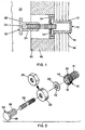
- an anchoring device 10 having external threads 12 adapted to be screwed into a hole 14 of a building structure 16.
- the anchoring device also includes a recessed portion 18 which contains and holds a speed nut mechanism 20 that is held in place by a screw cap 22.
- the screw cap 22 has internal threads 24 which threadingly engage external threads 26 on anchoring device 10.
- the screw cap 22 may be round as shown in the bottom of Fig. 2, or may have one or more flattened edge surfaces 28 (in this case 6) as shown in the top of Fig. 2 to aid in engaging and tightening the screw cap 22 to the anchoring device 10.
- Exterior material 30 such as a panel of stone, e.g., which is to be attached to the building structure 16 has a nut joint 32 embedded in a blind hole 34.
- the nut joint 32 has an extending flange 33 and an internally threaded receiving aperture 36.
- a separator rod 38 has one end screwed into the threaded aperture 36 of the nut joint 32 and the other end extending out from the face 40 of the material 30 to be attached to the structure 16.
- the speed nut mechanism 20 has a rachet means in the form of radially inwardly extending flaps 42.
- the exterior material 30 may be attached to the structure 16 by inserting the other end of the separator rod 38 into the anchoring device 10.
- the speed nut mechanism 20 rachet arrangement allows the separator rod 38 to advance into a receiving aperture 44 in the anchoring device 10, but inhibits outward movement of the separator rod 38.
- the exterior material 30 is thus held in place relative to the building structure 16, which preferably has an insulation layer 46 on the outside of the structure 16.
Landscapes
- Engineering & Computer Science (AREA)
- Architecture (AREA)
- Civil Engineering (AREA)
- Structural Engineering (AREA)
- Finishing Walls (AREA)
- Building Environments (AREA)
- Joining Of Building Structures In Genera (AREA)
- Furnace Housings, Linings, Walls, And Ceilings (AREA)
- Tents Or Canopies (AREA)
Claims (13)
- Système d'ancrage pour installer des matériaux extérieurs (30) sur une structure de construction (16), comprenant :caractérisé par le fait que ledit dispositif d'ancrage (10) comporte une partie d'extrémité agrandie (18) servant à recevoir un moyen de blocage (42), ladite partie d'extrémité (18) comportant un filetage extérieure (26), ledit dispositif d'ancrage (10) comprenant en outre un chapeau à vis taraudé (22) pour accouplement avec le filetage extérieur (26) et maintien du moyen de blocage (42).une tige de séparation (38) comportant deux extrémités ;un écrou (32) à encastrer dans un trou (34) réalisé dans la face latérale d'un matériau (30) à fixer à la structure (16), ledit écrou (32) comportant un moyen (36) destiné à recevoir et maintenir une extrémité de la tige de séparation (38) tout en permettant que l'autre extrémité de la tige de séparation (38) s'étende, en utilisation, de la face latérale (40) du matériau (30) à fixer vers la structure (16) ;un dispositif d'ancrage (10) pour montage sur la structure (16), ledit dispositif d'ancrage (10) comportant une ouverture de réception (44) dimensionnée pour recevoir l'autre extrémité de la tige de séparation (38), ledit dispositif d'ancrage (10) comprenant en outre un moyen de blocage destiné à permettre que l'autre extrémité de la tige de séparation (38) avance dans l'ouverture de réception (44), mais à interdire un déplacement de la tige de séparation (38) hors de l'ouverture de réception (44),
- Système d'ancrage selon la revendication 1, dans lequel la tige de séparation (38) comporte deux extrémités filetées.
- Système d'ancrage selon la revendication 1 ou 2, dans lequel l'écrou (32) à encastrer dans un trou est conçu pour, en utilisation, encastrement dans un trou borgne (34) réalisé dans le côté du matériau (30) à fixer à la structure (16).
- Système d'ancrage selon l'une quelconque des revendications précédentes, dans lequel l'écrou (32) comporte des ouvertures femelles taraudées (36), et dans lequel la première extrémité de la tige de séparation (38) comporte une extrémité mâle filetée dimensionnée de manière correspondante.
- Système d'ancrage selon l'une quelconque des revendications précédentes, dans lequel le moyen de blocage comprend des pattes (42) s'étendant radialement vers l'intérieur dans l'ouverture de réception (44), et dans lequel la tige de séparation (38) comporte une surface ondulée sur son autre extrémité pour engagement avec les pattes (42).
- Système d'ancrage selon l'une quelconque des revendications précédentes, dans lequel le dispositif d'ancrage (10) comprend un dispositif de fixation comportant une surface extérieure filetée (12) pour montage dans un trou (14) de la structure (16).
- Système d'ancrage selon l'une quelconque des revendications précédentes, dans lequel le dispositif d'ancrage (10) comprend :une partie d'extrémité agrandie (18) ;un écrou métal (20) reçu dans ladite partie d'extrémité agrandie (18) , ledit écrou métal (20) comportant des pattes s'étendant radialement vers l'intérieur (42) ; etdes moyens (22, 24, 26) servant à maintenir l'écrou métal (20) dans la partie d'extrémité agrandie (18).
- Système d'ancrage selon la revendication 1, dans lequel le chapeau à vis (22) comporte au moins une surface de rebord aplati (28) servant à aider à l'engagement par vissage du chapeau à vis (22) avec la partie d'extrémité agrandie (18).
- Système d'ancrage selon la revendication 8, dans lequel le chapeau à vis (22) comporte six surfaces de rebord aplati (28) agencées pour former un hexagone.
- Système pour installer des matériaux extérieurs (30) sur une structure de construction (16), comprenant :caractérisé par le fait que ledit dispositif d'ancrage (10) comporte une ouverture de réception (44), une partie d'extrémité agrandie (18) comportant un évidement plus grand que la structure de réception (44) et comportant une partie extérieure mâle filetée (12) et incluant un chapeau (22) comportant un moyen pour accouplement avec le dispositif d'ancrage, dans le but de maintenir la bague formant écrou (20) à l'intérieur de l'évidement (18), et par le fait qu'il comporte une ouverture pour alignement avec l'ouverture de réception (44), et dans lequel ledit écrou (32) comporte une ouverture de réception taraudée (36), dans laquelle la première partie d'extrémité de la tige de séparation (38) est filetée pour engagement par vissage avec l'ouverture de réception taraudée d'écrou (36) .un dispositif d'ancrage (10) à monter, en utilisation, dans un trou (14) réalisé dans la structure (16), ledit dispositif d'ancrage (10) comportant une bague formant écrou (20), ladite bague formant écrou (20) comportant des pattes (42) s'étendant radialement vers l'intérieur ;un écrou (32) comportant un moyen à monter, en utilisation, sur la face latérale (40) du matériau (30) à fixer à la structure (16) ;une tige de séparation (38) comportant des parties d'extrémité, incluant une première partie d'extrémité pour engagement à l'intérieur de l'écrou (32) et une seconde partie d'extrémité destinée à s'étendre, en utilisation, de la face latérale (40) du matériau (30) pour réception et maintien par les pattes de bague formant écrou (42) lorsqu'elle est reçue dans le dispositif d'ancrage,
- Procédé pour installation d'un matériau extérieur (30) sur une structure de construction (16), comprenant :caractérisé par le fait que ledit écrou (32) comporte un filetage intérieur (36), et dans lequel l'autre extrémité de la tige de séparation (38) comporte un filetage extérieur pour vissage dans l'écrou (32), dans lequel le dispositif d'ancrage (10) comporte un filetage extérieur (12) pour vissage dans un trou (14) réalisé dans la structure de construction (16).le montage d'un dispositif d'ancrage (10) sur la structure de construction (16), ledit dispositif d'ancrage (10) comportant une ouverture de réception (44) et des pattes (42) s'étendant plus radialement vers l'intérieur que le diamètre de l'ouverture de réception (44) de dispositif d'ancrage ;le montage d'un écrou (32) dans un trou (34) réalisé dans la face latérale (40) d'un matériau (30) à fixer à ladite structure (16) ;le montage d'une tige de séparation à deux extrémités (38) dans l'écrou (32), de sorte qu'une extrémité s'étend de la face latérale d'un matériau (30) à monter sur la structure (16) ; etl'introduction de l'autre extrémité de la tige de séparation (38) dans l'ouverture de réception (44) de dispositif d'ancrage (10), de sorte que les pattes (42) engagent et maintiennent la tige de séparation (38), ce par quoi le matériau extérieur (30) est fixé à la structure de construction (16) ;
- Système d'ancrage pour installer un matériau extérieur (30) sur une structure de construction (16), ladite structure (16) comportant un trou (14) défini dans celle-ci pour montage du matériau (30), comprenant :caractérisé par le fait que ledit dispositif d'ancrage (10) comporte un filetage extérieur (12) à visser dans un trou borgne (14) réalisé dans la structure de construction.une tige de séparation (38) comportant deux extrémités ;un dispositif d'ancrage (10) pour montage sur la structure (16), ledit dispositif d'ancrage (10) comportant une ouverture de réception (44) dimensionnée pour recevoir une extrémité de la tige de séparation (38), ledit dispositif d'ancrage (10) comprenant en outre un moyen de blocage servant à permettre que la première extrémité de la tige de séparation (38) avance dans l'ouverture de réception (44) et à interdire un déplacement de la tige de séparation (38) hors de l'ouverture de réception (44) ; etun écrou (32), ledit écrou (32) comportant un moyen (36) servant à recevoir et maintenir l'autre extrémité de la tige de séparation (38), ledit écrou (32) comportant un rebord s'étendant pour support et maintien du matériau de construction (30) sur l'extérieur de la construction après fixation, à la structure de construction (16), de l'écrou (32), de la tige de séparation (38) et du dispositif d'ancrage (10) ;
- Procédé pour installer un matériau extérieur (30) sur la surface extérieure d'une structure de construction (16), ladite structure (16) comportant un trou (14) défini dans celle-ci pour montage du matériau, comprenant :caractérisé par le fait que ledit dispositif d'ancrage (10) comporte un filetage extérieur (12), de sorte que le dispositif d'ancrage (10) se monte par vissage dans un trou borgne (14) réalisé dans la structure de construction (16),le montage d'un dispositif d'ancrage (10) sur la structure (16), ledit dispositif d'ancrage (10) comportant une ouverture de réception (44) dimensionnée pour recevoir et maintenir une extrémité d'une tige de séparation à deux extrémités (38) ; etl'exécution des étapes suivantes, pas nécessairement dans l'ordre mentionné : le montage de la première extrémité de la tige de séparation (38) sur un écrou (32), et l'introduction de l'autre extrémité de la tige de séparation (38) dans le dispositif d'ancrage (10),
dans lequel la première extrémité de la tige de séparation (38) comporte un filetage extérieur, et
dans lequel l'écrou (32) comporte un filetage intérieure (36) servant à maintenir et engager la première extrémité de la tige de séparation (38).
Applications Claiming Priority (3)
| Application Number | Priority Date | Filing Date | Title |
|---|---|---|---|
| US07/874,053 US5257490A (en) | 1992-04-24 | 1992-04-24 | Anchoring system for installing exterior materials to a building structure |
| US874053 | 1992-04-24 | ||
| PCT/US1993/003783 WO1993022514A1 (fr) | 1992-04-24 | 1993-04-22 | Systeme d'ancrage servant a fixer des materiaux exterieurs sur une structure de batiment |
Publications (3)
| Publication Number | Publication Date |
|---|---|
| EP0637355A1 EP0637355A1 (fr) | 1995-02-08 |
| EP0637355A4 EP0637355A4 (fr) | 1997-07-09 |
| EP0637355B1 true EP0637355B1 (fr) | 2004-02-11 |
Family
ID=25362886
Family Applications (1)
| Application Number | Title | Priority Date | Filing Date |
|---|---|---|---|
| EP93910718A Expired - Lifetime EP0637355B1 (fr) | 1992-04-24 | 1993-04-22 | Systeme d'ancrage servant a fixer des materiaux exterieurs sur une structure de batiment |
Country Status (8)
| Country | Link |
|---|---|
| US (1) | US5257490A (fr) |
| EP (1) | EP0637355B1 (fr) |
| JP (1) | JP3142872B2 (fr) |
| AT (1) | ATE259452T1 (fr) |
| AU (1) | AU670085B2 (fr) |
| CA (1) | CA2134232C (fr) |
| DE (1) | DE69333415T2 (fr) |
| WO (1) | WO1993022514A1 (fr) |
Cited By (1)
| Publication number | Priority date | Publication date | Assignee | Title |
|---|---|---|---|---|
| US20250198438A1 (en) * | 2023-12-15 | 2025-06-19 | Autex Industries Limited | Fixing of pet panels to allow for recycling |
Families Citing this family (28)
| Publication number | Priority date | Publication date | Assignee | Title |
|---|---|---|---|---|
| US5542225A (en) * | 1994-10-11 | 1996-08-06 | Endo; Shozo | Anchoring system for installing exterior materials to a building structure |
| US5625993A (en) * | 1995-01-06 | 1997-05-06 | The Burke Group | Concrete structure having load transferring insert and method for making same |
| CA2209664C (fr) * | 1995-01-06 | 2005-06-07 | The Burke Group | Structure en beton ayant un element d'insertion pour transferer des charges et procede de realisation |
| DE19515673A1 (de) * | 1995-04-28 | 1996-10-31 | Fischer Artur Werke Gmbh | Verbindungselement |
| US5732526A (en) * | 1996-06-24 | 1998-03-31 | Farley; Glenn | Repair procedure for delaminated container ceiling sheet and structure produced thereby |
| US5809703A (en) * | 1997-01-15 | 1998-09-22 | Mmi Products, Inc. | Slotted insert with increased pull-out capacity |
| US20040055236A1 (en) * | 2002-09-25 | 2004-03-25 | Keith David O. | Insulating connectors for securing insulation to an existing structure |
| AU2002951644A0 (en) * | 2002-09-25 | 2002-10-10 | Kerr, Michael | A device for mounting objects to walls |
| US7788860B2 (en) * | 2003-07-07 | 2010-09-07 | Zartman Ronald R | Vandal proof system for securing a frangible facing plate to rigid supporting structure by wedging action and a method therefor |
| DE202004005000U1 (de) * | 2004-03-27 | 2005-05-19 | Bau-Fritz Gmbh & Co. Kg, Seit 1896 | Holzbauverankerung, insbesondere für Fertighäuser |
| WO2009154805A1 (fr) * | 2008-06-20 | 2009-12-23 | Hunter Douglas Industries B. V. | Ensembles attache à profil bas, systèmes de montage de panneau et procédés associés |
| US8132389B2 (en) * | 2010-01-22 | 2012-03-13 | Gee Anthony F | Device and method for securing a bolt in concrete |
| US20120181402A1 (en) * | 2011-01-13 | 2012-07-19 | 3Form, Inc. | Adjustable bushing assemblies, panel mounting systems, and methods |
| US8752803B2 (en) * | 2012-04-06 | 2014-06-17 | Accurate Manufactured Products Group Inc. | Standoff adaptor for push pin |
| US9347232B1 (en) * | 2014-03-10 | 2016-05-24 | Sidney E. Francies, III | Lifting and leveling assembly for precast concrete slabs and method |
| US10370844B2 (en) * | 2015-06-03 | 2019-08-06 | Onguard Group Limited | Securing assembly |
| CN104989014A (zh) * | 2015-06-23 | 2015-10-21 | 上海龙人建设集团有限公司 | 石材幕墙于pc板的安装结构及其安装方法 |
| WO2017075332A1 (fr) * | 2015-10-29 | 2017-05-04 | A.L. Patterson, Inc. | Système d'ancrage en béton incorporé |
| US10597871B2 (en) | 2016-07-21 | 2020-03-24 | Meadow Burke, Llc | Lifting and leveling insert for a precast concrete slab |
| US10309103B2 (en) | 2016-07-21 | 2019-06-04 | Meadow Burke, Llc | Lifting and leveling insert for a precast concrete slab |
| KR102011716B1 (ko) * | 2017-05-19 | 2019-08-19 | 주식회사 메이크순 | 건축 슬래브용 인서트 |
| US10060144B1 (en) | 2017-12-01 | 2018-08-28 | Maestro International, Llc | Lifting and leveling assembly for precast concrete slabs and method |
| USD882905S1 (en) | 2018-05-31 | 2020-04-28 | Meadow Burke, Llc | Lift level |
| CN109281413B (zh) * | 2018-09-13 | 2023-12-26 | 深圳市建艺装饰集团股份有限公司 | 复合式装饰外保温外墙及施工方法 |
| US11447960B2 (en) * | 2019-09-19 | 2022-09-20 | Andrew J. Batten | Wall panel system |
| CA3187017C (fr) * | 2019-09-19 | 2025-08-05 | Andrew J. Batten | Systeme de panneau mural |
| CN111877568B (zh) * | 2020-09-04 | 2024-10-22 | 安徽马钢比亚西钢筋焊网有限公司 | 一种钢-pvc护筒铰接型墙板预埋件装置及其制作方法 |
| WO2024025925A1 (fr) * | 2022-07-26 | 2024-02-01 | Certainteed Gypsum, Inc. | Produit de surface de bâtiment comprenant un élément de fixation intégré, système de surface de bâtiment et procédé de fabrication |
Family Cites Families (8)
| Publication number | Priority date | Publication date | Assignee | Title |
|---|---|---|---|---|
| CH390507A (de) * | 1961-08-21 | 1965-04-15 | Jeker Hugo | Vorrichtung zum lösbaren Befestigen von Platten an Decken oder Wänden |
| US4097061A (en) * | 1976-04-19 | 1978-06-27 | Dietlein Robert W | Ski insert for anchoring a ski binding screw in a ski |
| CH598438A5 (en) * | 1976-12-23 | 1978-04-28 | Braendli August | Clamp for facing and internal lining panels for wall or ceiling |
| IT7709526U1 (it) * | 1977-09-08 | 1979-03-08 | Salice Arturo Spa | Inserto metallico per manufatti di materia plastica o legno |
| DE3618486C1 (de) * | 1985-07-19 | 1987-08-06 | United Carr Gmbh Trw | Kunststoffteil zur Halterung eines Gewindebolzens |
| US4860516A (en) * | 1988-01-15 | 1989-08-29 | Koller Gregory V | Portable cushioned floor system |
| US4899513A (en) * | 1989-01-25 | 1990-02-13 | Morris Phillip L | Anchor for simulated marble panels |
| FR2642482A1 (fr) * | 1989-02-01 | 1990-08-03 | Avdel | Dispositif d'attache particulierement destine a la fixation de panneaux |
-
1992
- 1992-04-24 US US07/874,053 patent/US5257490A/en not_active Expired - Lifetime
-
1993
- 1993-04-22 WO PCT/US1993/003783 patent/WO1993022514A1/fr not_active Ceased
- 1993-04-22 AU AU41113/93A patent/AU670085B2/en not_active Ceased
- 1993-04-22 EP EP93910718A patent/EP0637355B1/fr not_active Expired - Lifetime
- 1993-04-22 AT AT93910718T patent/ATE259452T1/de not_active IP Right Cessation
- 1993-04-22 JP JP05519370A patent/JP3142872B2/ja not_active Expired - Fee Related
- 1993-04-22 DE DE69333415T patent/DE69333415T2/de not_active Expired - Fee Related
- 1993-04-22 CA CA002134232A patent/CA2134232C/fr not_active Expired - Fee Related
Cited By (1)
| Publication number | Priority date | Publication date | Assignee | Title |
|---|---|---|---|---|
| US20250198438A1 (en) * | 2023-12-15 | 2025-06-19 | Autex Industries Limited | Fixing of pet panels to allow for recycling |
Also Published As
| Publication number | Publication date |
|---|---|
| US5257490A (en) | 1993-11-02 |
| CA2134232A1 (fr) | 1993-11-11 |
| JPH07508801A (ja) | 1995-09-28 |
| AU4111393A (en) | 1993-11-29 |
| EP0637355A1 (fr) | 1995-02-08 |
| ATE259452T1 (de) | 2004-02-15 |
| AU670085B2 (en) | 1996-07-04 |
| CA2134232C (fr) | 2004-06-22 |
| DE69333415D1 (de) | 2004-03-18 |
| JP3142872B2 (ja) | 2001-03-07 |
| EP0637355A4 (fr) | 1997-07-09 |
| WO1993022514A1 (fr) | 1993-11-11 |
| DE69333415T2 (de) | 2005-03-03 |
Similar Documents
| Publication | Publication Date | Title |
|---|---|---|
| EP0637355B1 (fr) | Systeme d'ancrage servant a fixer des materiaux exterieurs sur une structure de batiment | |
| US5542225A (en) | Anchoring system for installing exterior materials to a building structure | |
| US8950157B1 (en) | Solar panel tile roof mounting device installation method | |
| HK16895A (en) | Fastening element | |
| CA3168297A1 (fr) | Systeme de fixation de facade comportant des elements profiles | |
| US4838002A (en) | Clip fastener securable to ceiling T-bar to retain wall partition in position | |
| US5303521A (en) | Fascia panel | |
| US6709211B1 (en) | Girt or purlin retainer and method of using same | |
| CN216109499U (zh) | 一种墙面装饰板紧固件 | |
| JPH036740Y2 (fr) | ||
| CN220203147U (zh) | 龙骨连接块及吊装结构 | |
| JPS624108Y2 (fr) | ||
| AU694544B2 (en) | Fastener for corrugated sheeting | |
| JPS5854512Y2 (ja) | 笠木の取付け構造 | |
| KR200234583Y1 (ko) | 단열방수겸용 패널용고정장치 | |
| JPH0748851Y2 (ja) | タイルのモザイク貼り施工構造 | |
| JPH11107460A (ja) | 屋根瓦の固定具 | |
| JPS6032261Y2 (ja) | 波板取付用締付金具 | |
| US7467497B2 (en) | Toggle lock for snow guards or the like | |
| KR0126613Y1 (ko) | 세면대용 지주부재 | |
| KR100676490B1 (ko) | 천장 마감패널 설치용 너트홀더 및 체결너트 | |
| JPH0715935Y2 (ja) | 軒天井取付装置 | |
| JPH0428350Y2 (fr) | ||
| JPH05255999A (ja) | 屋根材取付具及び屋根構造 | |
| JPH0539130Y2 (fr) |
Legal Events
| Date | Code | Title | Description |
|---|---|---|---|
| PUAI | Public reference made under article 153(3) epc to a published international application that has entered the european phase |
Free format text: ORIGINAL CODE: 0009012 |
|
| AK | Designated contracting states |
Kind code of ref document: A1 Designated state(s): AT BE CH DE DK ES FR GB GR IE IT LI LU MC NL PT SE |
|
| 17P | Request for examination filed |
Effective date: 19941123 |
|
| A4 | Supplementary search report drawn up and despatched |
Effective date: 19970520 |
|
| AK | Designated contracting states |
Kind code of ref document: A4 Designated state(s): AT BE CH DE DK ES FR GB GR IE IT LI LU MC NL PT SE |
|
| 17Q | First examination report despatched |
Effective date: 20000119 |
|
| GRAH | Despatch of communication of intention to grant a patent |
Free format text: ORIGINAL CODE: EPIDOS IGRA |
|
| GRAS | Grant fee paid |
Free format text: ORIGINAL CODE: EPIDOSNIGR3 |
|
| GRAA | (expected) grant |
Free format text: ORIGINAL CODE: 0009210 |
|
| AK | Designated contracting states |
Kind code of ref document: B1 Designated state(s): AT BE CH DE DK ES FR GB GR IE IT LI LU MC NL PT SE |
|
| PG25 | Lapsed in a contracting state [announced via postgrant information from national office to epo] |
Ref country code: NL Free format text: LAPSE BECAUSE OF FAILURE TO SUBMIT A TRANSLATION OF THE DESCRIPTION OR TO PAY THE FEE WITHIN THE PRESCRIBED TIME-LIMIT Effective date: 20040211 Ref country code: LI Free format text: LAPSE BECAUSE OF FAILURE TO SUBMIT A TRANSLATION OF THE DESCRIPTION OR TO PAY THE FEE WITHIN THE PRESCRIBED TIME-LIMIT Effective date: 20040211 Ref country code: IT Free format text: LAPSE BECAUSE OF FAILURE TO SUBMIT A TRANSLATION OF THE DESCRIPTION OR TO PAY THE FEE WITHIN THE PRE;WARNING: LAPSES OF ITALIAN PATENTS WITH EFFECTIVE DATE BEFORE 2007 MAY HAVE OCCURRED AT ANY TIME BEFORE 2007. THE CORRECT EFFECTIVE DATE MAY BE DIFFERENT FROM THE ONE RECORDED.SCRIBED TIME-LIMIT Effective date: 20040211 Ref country code: FR Free format text: LAPSE BECAUSE OF FAILURE TO SUBMIT A TRANSLATION OF THE DESCRIPTION OR TO PAY THE FEE WITHIN THE PRESCRIBED TIME-LIMIT Effective date: 20040211 Ref country code: CH Free format text: LAPSE BECAUSE OF FAILURE TO SUBMIT A TRANSLATION OF THE DESCRIPTION OR TO PAY THE FEE WITHIN THE PRESCRIBED TIME-LIMIT Effective date: 20040211 Ref country code: BE Free format text: LAPSE BECAUSE OF FAILURE TO SUBMIT A TRANSLATION OF THE DESCRIPTION OR TO PAY THE FEE WITHIN THE PRESCRIBED TIME-LIMIT Effective date: 20040211 Ref country code: AT Free format text: LAPSE BECAUSE OF FAILURE TO SUBMIT A TRANSLATION OF THE DESCRIPTION OR TO PAY THE FEE WITHIN THE PRESCRIBED TIME-LIMIT Effective date: 20040211 |
|
| REG | Reference to a national code |
Ref country code: GB Ref legal event code: FG4D |
|
| REG | Reference to a national code |
Ref country code: CH Ref legal event code: EP |
|
| REG | Reference to a national code |
Ref country code: SE Ref legal event code: TRGR |
|
| REG | Reference to a national code |
Ref country code: IE Ref legal event code: FG4D |
|
| REF | Corresponds to: |
Ref document number: 69333415 Country of ref document: DE Date of ref document: 20040318 Kind code of ref document: P |
|
| PG25 | Lapsed in a contracting state [announced via postgrant information from national office to epo] |
Ref country code: LU Free format text: LAPSE BECAUSE OF NON-PAYMENT OF DUE FEES Effective date: 20040422 Ref country code: IE Free format text: LAPSE BECAUSE OF NON-PAYMENT OF DUE FEES Effective date: 20040422 |
|
| PG25 | Lapsed in a contracting state [announced via postgrant information from national office to epo] |
Ref country code: MC Free format text: LAPSE BECAUSE OF NON-PAYMENT OF DUE FEES Effective date: 20040430 |
|
| PG25 | Lapsed in a contracting state [announced via postgrant information from national office to epo] |
Ref country code: GR Free format text: LAPSE BECAUSE OF FAILURE TO SUBMIT A TRANSLATION OF THE DESCRIPTION OR TO PAY THE FEE WITHIN THE PRESCRIBED TIME-LIMIT Effective date: 20040511 Ref country code: GB Free format text: LAPSE BECAUSE OF NON-PAYMENT OF DUE FEES Effective date: 20040511 Ref country code: DK Free format text: LAPSE BECAUSE OF FAILURE TO SUBMIT A TRANSLATION OF THE DESCRIPTION OR TO PAY THE FEE WITHIN THE PRESCRIBED TIME-LIMIT Effective date: 20040511 |
|
| PG25 | Lapsed in a contracting state [announced via postgrant information from national office to epo] |
Ref country code: ES Free format text: LAPSE BECAUSE OF FAILURE TO SUBMIT A TRANSLATION OF THE DESCRIPTION OR TO PAY THE FEE WITHIN THE PRESCRIBED TIME-LIMIT Effective date: 20040522 |
|
| NLV1 | Nl: lapsed or annulled due to failure to fulfill the requirements of art. 29p and 29m of the patents act | ||
| REG | Reference to a national code |
Ref country code: CH Ref legal event code: PL |
|
| PLBE | No opposition filed within time limit |
Free format text: ORIGINAL CODE: 0009261 |
|
| STAA | Information on the status of an ep patent application or granted ep patent |
Free format text: STATUS: NO OPPOSITION FILED WITHIN TIME LIMIT |
|
| GBPC | Gb: european patent ceased through non-payment of renewal fee |
Effective date: 20040511 |
|
| EN | Fr: translation not filed | ||
| 26N | No opposition filed |
Effective date: 20041112 |
|
| REG | Reference to a national code |
Ref country code: IE Ref legal event code: MM4A |
|
| PGFP | Annual fee paid to national office [announced via postgrant information from national office to epo] |
Ref country code: DE Payment date: 20050415 Year of fee payment: 13 |
|
| PGFP | Annual fee paid to national office [announced via postgrant information from national office to epo] |
Ref country code: SE Payment date: 20050419 Year of fee payment: 13 |
|
| PG25 | Lapsed in a contracting state [announced via postgrant information from national office to epo] |
Ref country code: SE Free format text: LAPSE BECAUSE OF NON-PAYMENT OF DUE FEES Effective date: 20060423 |
|
| PG25 | Lapsed in a contracting state [announced via postgrant information from national office to epo] |
Ref country code: DE Free format text: LAPSE BECAUSE OF NON-PAYMENT OF DUE FEES Effective date: 20061101 |
|
| EUG | Se: european patent has lapsed | ||
| PG25 | Lapsed in a contracting state [announced via postgrant information from national office to epo] |
Ref country code: PT Free format text: LAPSE BECAUSE OF NON-PAYMENT OF DUE FEES Effective date: 20040711 |