EP0637533B1 - Stützvorrichtung für ein Bergefahrzeug - Google Patents
Stützvorrichtung für ein Bergefahrzeug Download PDFInfo
- Publication number
- EP0637533B1 EP0637533B1 EP94111401A EP94111401A EP0637533B1 EP 0637533 B1 EP0637533 B1 EP 0637533B1 EP 94111401 A EP94111401 A EP 94111401A EP 94111401 A EP94111401 A EP 94111401A EP 0637533 B1 EP0637533 B1 EP 0637533B1
- Authority
- EP
- European Patent Office
- Prior art keywords
- plates
- footing
- supporting device
- plate
- shield
- Prior art date
- Legal status (The legal status is an assumption and is not a legal conclusion. Google has not performed a legal analysis and makes no representation as to the accuracy of the status listed.)
- Expired - Lifetime
Links
- 238000011084 recovery Methods 0.000 title description 7
- 230000008878 coupling Effects 0.000 claims description 4
- 238000010168 coupling process Methods 0.000 claims description 4
- 238000005859 coupling reaction Methods 0.000 claims description 4
- 230000000694 effects Effects 0.000 description 1
- 238000005065 mining Methods 0.000 description 1
- 230000002787 reinforcement Effects 0.000 description 1
Images

Classifications
-
- F—MECHANICAL ENGINEERING; LIGHTING; HEATING; WEAPONS; BLASTING
- F41—WEAPONS
- F41H—ARMOUR; ARMOURED TURRETS; ARMOURED OR ARMED VEHICLES; MEANS OF ATTACK OR DEFENCE, e.g. CAMOUFLAGE, IN GENERAL
- F41H7/00—Armoured or armed vehicles
- F41H7/02—Land vehicles with enclosing armour, e.g. tanks
-
- B—PERFORMING OPERATIONS; TRANSPORTING
- B60—VEHICLES IN GENERAL
- B60S—SERVICING, CLEANING, REPAIRING, SUPPORTING, LIFTING, OR MANOEUVRING OF VEHICLES, NOT OTHERWISE PROVIDED FOR
- B60S9/00—Ground-engaging vehicle fittings for supporting, lifting, or manoeuvring the vehicle, wholly or in part, e.g. built-in jacks
- B60S9/02—Ground-engaging vehicle fittings for supporting, lifting, or manoeuvring the vehicle, wholly or in part, e.g. built-in jacks for only lifting or supporting
- B60S9/10—Ground-engaging vehicle fittings for supporting, lifting, or manoeuvring the vehicle, wholly or in part, e.g. built-in jacks for only lifting or supporting by fluid pressure
-
- B—PERFORMING OPERATIONS; TRANSPORTING
- B66—HOISTING; LIFTING; HAULING
- B66C—CRANES; LOAD-ENGAGING ELEMENTS OR DEVICES FOR CRANES, CAPSTANS, WINCHES, OR TACKLES
- B66C23/00—Cranes comprising essentially a beam, boom, or triangular structure acting as a cantilever and mounted for translatory of swinging movements in vertical or horizontal planes or a combination of such movements, e.g. jib-cranes, derricks, tower cranes
- B66C23/62—Constructional features or details
- B66C23/72—Counterweights or supports for balancing lifting couples
- B66C23/78—Supports, e.g. outriggers, for mobile cranes
- B66C23/80—Supports, e.g. outriggers, for mobile cranes hydraulically actuated
-
- E—FIXED CONSTRUCTIONS
- E02—HYDRAULIC ENGINEERING; FOUNDATIONS; SOIL SHIFTING
- E02F—DREDGING; SOIL-SHIFTING
- E02F3/00—Dredgers; Soil-shifting machines
- E02F3/04—Dredgers; Soil-shifting machines mechanically-driven
- E02F3/76—Graders, bulldozers, or the like with scraper plates or ploughshare-like elements; Levelling scarifying devices
- E02F3/80—Component parts
- E02F3/815—Blades; Levelling or scarifying tools
-
- E—FIXED CONSTRUCTIONS
- E02—HYDRAULIC ENGINEERING; FOUNDATIONS; SOIL SHIFTING
- E02F—DREDGING; SOIL-SHIFTING
- E02F9/00—Component parts of dredgers or soil-shifting machines, not restricted to one of the kinds covered by groups E02F3/00 - E02F7/00
- E02F9/08—Superstructures; Supports for superstructures
- E02F9/085—Ground-engaging fitting for supporting the machines while working, e.g. outriggers, legs
Definitions
- the invention relates to a support device for a recovery vehicle, which consists of two legs, which are arranged near the side of the vehicle and can be swiveled downward from a transport position into a support position with support plates.
- Such well-known support devices have the purpose of supporting the vehicle when lifting a load by means of a cantilever arm so that its tipping edge comes as close as possible to the intersection of the load application line with the ground.
- recovery vehicles for military purposes: On the one hand, they must also offer protection to the repair teams carried along and facilitate their disembarking and working under cover. For this reason, the lifting range and support and also an exit door should be provided at the rear of the vehicle.
- the support plates are connected to the legs so as to be pivotable about a horizontal and a vertical axis and in that both support plates can be connected to one another to form a support plate.
- the contact plates can be brought into two different working positions. To absorb vertical forces, they lie individually flat on the ground, so that they do not sink easily; to absorb horizontal forces, they are swiveled around both axes and can thus form a shield that extends across the entire width of the vehicle and also pushes into the ground with the correct angle of attack.
- the contact plates preferably consist of a base plate and a shield plate, which enclose an obtuse angle with one another and can be connected to one another (claim 2). This creates a sign that extends across the entire width of the vehicle, the blunt V-shape of which favors support in the horizontal direction.
- a joint bracket is provided between the legs and the support plate, which is connected to the leg is connected by a horizontal axis of rotation and to the support plate by a vertical pivot (claim 3). This means that it can be swiveled around two axes easily and without a ball joint.
- one end of a strut engages eccentrically to the vertical pivot on the joint bracket and the other end of the leg (claim 4).
- the strut holds the support plate in the transport position as well as in the working position to absorb vertical forces.
- Another fastening tab for the strut on the leg allows the support plate to be held in the position for horizontal force application (claim 5).
- a pressure strut can be attached between the vehicle body and the shield plate (claim 6).
- the connecting means of the contact plates in the working position are arranged in front of the shield plates with a connection coupling (claim 7), the shovel formed by the contact plates can finally be used to lift a damaged vehicle.
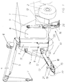
- the body of the recovery vehicle is designated 1 and the wheels with 2.
- Fixed lower crane part 3 which has the usual lifting and rotating devices, not shown, for a cantilever arm 4, the azimuth of which is adjustable by a lifting cylinder 5.
- the cantilever arm 4 is equipped with a hoist winch 6 and with a crane hook 7.
- an exit door 8 for the crew is provided at the rear of the vehicle 1, an exit slot 9 for the pull rope 25 (FIG. 2) of a winch accommodated in the interior of the vehicle body 1 for exerting an approximately horizontal pulling force, as well as support devices 10.
- the vehicle body 1 carries upper fastening eyes 11 and lower fastening eyes 12 on both sides, on each of which a leg 13 is pivotably mounted about a vertical and a horizontal axis.
- a support plate 16 is movably arranged in a manner to be described in more detail below via a joint bracket 15.
- Each support plate 16 consists of a base plate 17 and a shield plate 18 which together form an obtuse angle 26.
- a strut 19 is provided between the shield plate 18 and the joint bracket 15 or leg 13 and a pressure strut 20 at the rear of the vehicle body 1. This is discussed in more detail below with reference to FIG. In Figure 1, the legs 13 are in the position in which they can transmit vertical forces to the ground when the vehicle is used as a crane, with approximately vertical forces acting on the crane hook 7.
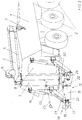
- the support plates 16 are brought into another position, in which they brace themselves against the ground as a shield and in a manner to be described two mutually orthogonal axes are pivoted, connected to one another by means of the connecting means 22 and are supported on the vehicle body 1 via the pressure strut 20.
- FIG. 3 shows the same vehicle in the transport position, in which the legs 13 are folded up completely by means of the hydraulic cylinders 14, the fastening tabs 21 (visible in FIG. 2) engaging in the upper fastening eyes 11.
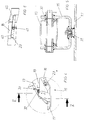
- leg 13 and support plate 16 can be seen more precisely.
- a horizontal axis of rotation 30 is provided between the leg 13 and the joint bracket 15, about which the joint bracket 15 can be pivoted.
- this bracket 15 is connected to the base plate 17 via a vertical pivot pin 31, which enables its rotation about a vertical axis.
- the strut 19, which is fastened at one end to the shield plate 18, is supported at its other end at a first fastening tab 32, which is firmly connected to the articulated console 15 at a position which is vertical Pivot 31 is eccentric.
- the strut 19 thus holds the support plate 16 in the position shown in FIG.
- the connection between the strut 19 and the first fastening bracket 32 is released, the support plate 16 is rotated around the vertical pin 31 first, and then the hinge bracket 15 with the support plate 16 the horizontal axis 30 rotated until the base plate 17 is approximately vertical.
- the two shield plates 18 are connected to one another by means of the connecting elements 22 (FIGS. 1, 2) and the strut 19 is connected to a second fastening tab 33 which, in contrast to the first fastening tab 32, is fastened to the leg 13.
- FIG. 1 Another connection of the two shield plates 18 is indicated in FIG.
- beams 40 are screwed, which are connected to one another via a connecting coupling 41.
- This connection coupling 41 can also be used to lift an axle of a damaged vehicle off the ground and to tow it in this way.
Landscapes
- Engineering & Computer Science (AREA)
- Mechanical Engineering (AREA)
- General Engineering & Computer Science (AREA)
- Mining & Mineral Resources (AREA)
- Civil Engineering (AREA)
- Structural Engineering (AREA)
- Physics & Mathematics (AREA)
- Fluid Mechanics (AREA)
- Jib Cranes (AREA)
- Emergency Lowering Means (AREA)
- Vehicle Cleaning, Maintenance, Repair, Refitting, And Outriggers (AREA)
- Aiming, Guidance, Guns With A Light Source, Armor, Camouflage, And Targets (AREA)
- Air-Conditioning For Vehicles (AREA)
Description
- Die Erfindung betrifft eine Stützvorrichtung für ein Bergefahrzeug, die aus zwei nahe der Fahrzeugseitenkante angeordneten aus einer Transportstellung abwärts in eine Stützstellung schwenkbaren Beinen mit Aufstandsplatten besteht.
- Derartige allgemein bekannte Stützvorrichtungen haben den Zweck, das Fahrzeug beim Heben einer Last mittels eines Kragarmes so abzustützen, daß dessen Kippkante möglichst nahe an den Schnittpunkt der Lastangriffslinie mit dem Boden heranrückt. An Bergefahrzeuge für militärische Zwecke werden aber noch weitere Forderungen gestellt: Zum Einen müssen sie auch den mitgeführten Instandsetzungsmannschaften Schutz bieten und deren gedecktes Aussteigen und Arbeiten erleichtern. Deshalb sollen Hubbereich und Abstützung und auch eine Ausstiegstür am Heck des Fahrzeuges vorgesehen sein. Zum Anderen ist es oft auch notwendig, ein beschädigtes Fahrzeug mittels einer bordeigenen Seilwinde zu ziehen, vor allem wenn es zu schwer ist, um gehoben zu werden. Dazu sind erhebliche Zugkräfte nötig, die die Haltekraft der Bremsen übersteigen und bei Radfahrzeugen auch die Bodenhaftung der Räder. Es ist also auch eine Abstützung in horizontaler Richtung nötig.
- Aus der DE-C 30 39 364 ist zwar ein Räumschild für einen Bergepanzer bekannt, der dem Fahrzeug sowohl in horizontaler als auch in vertikaler Richtung Stütze bietet. Er erstreckt sich jedoch über die ganze Breite des Fahrzeuges, was nicht nur hohes Eigengewicht und hohe Kosten bedeutet, sondern auch den Ausstieg an der Stirnwand unmöglich macht. Trotzdem ist die horizontale Abstützwirkung begrenzt, weil die Unterkante des Schildes lieber nach Art einer Planieraupe Boden abheben würde als das Fahrzeug am Boden festzuhalten.
- Es ist daher Ziel der Erfindung, eine leichte und trotzdem in beiden Zugrichtungen gut wirksame Stützvorrichtung zu schaffen, die zudem leicht einziehbar und gut zugänglich ist.
- Erfindungsgemäß wird das dadurch erreicht, daß die Aufstandplatten mit den Beinen um eine horizontale und um eine vertikale Achse schwenkbar verbunden sind und daß beide Aufstandsplatten zur Bildung eines Stützschildes miteinander verbindbar sind.
- So können die Aufstandsplatten in zwei verschiedene Arbeitsstellungen gebracht werden. Zum Aufnehmen vertikaler Kräfte liegen sie einzeln flächig am Boden auf, wodurch sie nicht leicht einsinken; zum Aufnehmen horizontaler Kräfte werden sie um beide Achsen geschwenkt und können so einen sich über die ganze Breite des Fahrzeuges erstreckenden Schild bilden, der sich zudem auch noch mit dem richtigen Anstellwinkel in den Boden stemmt.
- Dabei bestehen die Aufstandsplatten vorzugsweise aus einer Fußplatte und einer Schildplatte, die miteinander einen stumpfen Winkel einschließen und miteinander verbindbar sind (Anspruch 2). So entsteht ein sich über die gesamte Fahrzeugbreite erstreckender Schild, dessen stumpfe V-Form die Abstützung in horizontaler Richtung begünstigt.
- In einer Weiterbildung ist zwischen den Beinen und der Aufstandsplatte eine Gelenkkonsole vorgesehen, die mit dem Bein durch eine horizontale Drehachse und mit der Aufstandsplatte durch einen vertikalen Drehzapfen verbunden ist (Anspruch 3). Dadurch ist die Schwenkbarkeit um zwei Achsen ganz einfach und ohne Kugelgelenk realisiert.
- Vorzugsweise greift an der Gelenkkonsole ein Ende einer Strebe exzentrisch zum vertikalen Drehzapfen an und deren anderes Ende am Bein (Anspruch 4). Die Strebe hält sowohl in der Transportstellung als auch in der Arbeitsstellung zur Aufnahme vertikaler Kräfte die Aufstandplatte fest. Eine weitere Befestigungslasche für die Strebe am Bein erlaubt es, die Aufstandsplatte auch in der Stellung für horizontalen Kraftangriff festzuhalten (Anspruch 5).
- Zur weiteren Verstärkung bei horizontalem Kraftangriff kann eine Druckstrebe zwischen Fahrzeugkörper und der Schildplatte angebracht sein (Anspruch 6). Wenn schließlich noch die Verbindungsmittel der Aufstandsplatten in Arbeitsstellung vor den Schildplatten angeordnete Träger mit einer Verbindungskupplung sind (Anspruch 7), kann die von den Aufstandsplatten gebildete Schaufel schließlich noch zum Anheben eines havarierten Fahrzeuges verwendet werden.
- Im folgenden wird die Erfindung anhand von Abbildungen beschrieben und erläutert. Es stellen dar:
- Figur 1:
- Ein Bergefahrzeug mit der erfindungsgemäßen Vorrichtung in einer ersten Arbeitsstellung;
- Figur 2:
- Dasselbe Bergefahrzeug in einer zweiten Arbeitsstellung;
- Figur 3:
- Dasselbe Fahrzeug in Transportstellung;
- Figur 4:
- Detail IV von Figur 1, vergrößert;
- Figur 5:
- Schnitt V-V in Figur 4, vergrößert;
- Figur 6:
- Detailvariante zu Fig.1.
- In Fig.1 ist der Körper des Bergefahrzeuges mit 1 bezeichnet und die Räder mit 2. Dazu ist am Heck des Fahrzeugkörpers 1 ein Kranunterteil 3 befestigt, das die üblichen nicht dargestellten Hebe- und Drehvorrichtungen für einen Kragarm 4 aufweist, dessen Azimut durch einen Hubzylinder 5 verstellbar ist. Der Kragarm 4 ist mit einer Hubwinde 6 und mit einem Kranhaken 7 ausgerüstet.
- Weiters ist am Heck des Fahrzeuges 1 eine Ausstiegstür 8 für die Mannschaft vorgesehen, ein Ausgangsschlitz 9 für das Zugseil 25 (Fig.2) einer im Inneren des Fahrzeugkörpers 1 untergebrachten Seilwinde zum Ausüben einer ungefähr horizontalen Zugkraft, sowie Abstützvorrichtungen 10 angebracht.
- Für die Abstützvorrichtung trägt der Fahrzeugkörper 1 beiderseits obere Befestigungsösen 11 und untere Befestigungsösen 12, an an welchen beiden je ein Bein 13 um eine vertikale und eine horizontale Achse schwenkbar gelagert ist. An den Beinen 13 greifen weiters Hydraulikzylinder 14 an, die sich über die oberen Befestigungsösen 11 am Fahrzeugkörper 1 abstützen. Am äußeren Ende jedes Beines 13 ist über eine Gelenkkonsole 15 eine Aufstandplatte 16 in noch näher zu beschreibender Weise beweglich angeordnet. Jede Aufstandplatte 16 besteht aus einer Fußplatte 17 und aus einer Schildplatte 18, die miteinander einen stumpfen Winkel 26 einschließen. Zwischen Schildplatte 18 und Gelenkkonsole 15 bzw Bein 13 ist eine Strebe 19 vorgesehen und am Heck des Fahrzeugkörpers 1 eine Druckstrebe 20. Auf diese wird weiter unten anhand von Fig.2 näher eingegangen. In Fig.1 befinden sich die Beine 13 in der Stellung, in der sie vertikale Kräfte auf den Boden übertragen können, wenn das Fahrzeug als Kran benützt wird, wobei auf den Kranhaken 7 angenähert vertikale Kräfte wirken.
- Fig.2 zeigt dasselbe Fahrzeug bei der Benutzung der auf das Seil 25 wirkenden Seilwinde, wobei die Abstützvorrichtungen 10 angenähert horizontale Kräfte auf den Boden zu übertragen haben. Zu diesem Zweck sind die Aufstandsplatten 16 in eine andere Stellung gebracht, in der sie sich gemeinsam als Schild gegen den Boden stemmen und in noch zu beschreibender Weise um zwei zueinander orthogonale Achsen verschwenkt, mittels der Verbindungsmittel 22 miteinander verbunden und über die Druckstrebe 20 am Fahrzeugkörper 1 abgestützt sind.
- In Fig.3 ist dasselbe Fahrzeug noch in Transportstellung gezeigt, in der die Beine 13 mittels der Hydraulikzylinder 14 ganz hochgeklappt sind, wobei die Befestigungslaschen 21 (in Fig.2 sichtbar) in die oberen Befestigungsösen 11 eingreifen.
- In Fig.4 und 5 ist die Verbindung zwischen Bein 13 und Aufstandsplatte 16 genauer zu erkennen. Zwischen dem Bein 13 und der Gelenkkonsole 15 ist eine horizontale Drehachse 30 vorgesehen, um die die Gelenkkonsole 15 schwenkbar ist. Weiters ist diese Konsole 15 über einen vertikalen Drehzapfen 31 mit der Fußplatte 17 verbunden, der ihre Drehung um eine vertikale Achse ermöglicht. In der Arbeitsstellung der Fig.1 ist die Strebe 19, die mit einem Ende an der Schildplatte 18 befestigt ist, mit ihrem anderen Ende an einer ersten Befestigungslasche 32 abgestützt, die mit der Gelenkkonsole 15 an einer Stelle fest verbunden ist, die bezüglich des vertikalen Drehzapfens 31 exzentrisch ist. So hält die Strebe 19 die Aufstandsplatte 16 in der in Fig.1 gezeigten Stellung.
- Soll die Aufstandsplatte 16 nun in die Stellung der Fig.2 gebracht werden, so wird die Verbindung zwischen der Strebe 19 und der ersten Befestigungslasche 32 gelöst, die Aufstandsplatte 16 um den vertikalen Zapfen 31 zuerst gedreht und dann die Gelenkkonsole 15 mit der Aufstandsplatte 16 um die horizontale Achse 30 gedreht, bis die Fußplatte 17 angenähert senkrecht ist. Nun werden die beiden Schildplatten 18 mittels der Verbindungselemente 22 (Fig.1,2) miteinander und die Strebe 19 mit einer zweiten Befestigungslasche 33 verbunden, die zum Unterschied von der ersten Befestigungslasche 32 am Bein 13 befestigt ist.
- In Fig.6 ist schließlich noch eine andere Verbindung der beiden Schildplatten 18 angedeutet. An den Schraubblöcken 23 (siehe auch Fig.2, Fig.4) und gegebenenfalls noch an weiteren nicht gezeigten Stellen sind Träger 40 angeschraubt, die über eine Verbindungskupplung 41 miteinander verbunden sind. Diese Verbindungskupplung 41 kann auch benützt werden, um eine Achse eines beschädigten Fahrzeuges vom Boden abzuheben und es auf diese Weise abzuschleppen.
- Insgesamt wird durch die Erfindung eine besonders leichte und vielseitige Abstützvorrichtung geschaffen, die trotzdem alle im Bergedienst auftretenden Kräfte in den Boden einleiten kann.
Claims (7)
- Stützvorrichtung für ein Bergefahrzeug, die aus zwei nahe der Fahrzeugseitenkante angeordneten aus einer Transportstellung abwärts in eine Stützstellung schwenkbaren Beinen (13) mit Aufstandsplatten (16) besteht, dadurch gekennzeichnet, daß die Aufstandsplatten (16) mit den Beinen (13) um eine horizontale (30) und um eine vertikale (31) Achse schwenkbar verbunden sind und daß beide Aufstandsplatten (16) zur Bildung eines Stützschildes miteinander verbindbar sind.
- Stützvorrichtung nach Anspruch 1, dadurch gekennzeichnet, daß die Aufstandsplatten (16) aus einer Fußplatte (17) und einer Schildplatte (18) bestehen, die miteinander einen stumpfen Winkel (26) einschließen, wobei die Schildplatten (18) Verbindungsmittel (22) aufweisen.
- Stützvorrichtung nach Anspruch 1, dadurch gekennzeichnet, daß zwischen den Beinen (13) und der Aufstandsplatte (16) eine Gelenkkonsole (15) vorgesehen ist, die mit dem Bein (13) durch eine horizontale Drehachse (30) und mit der Aufstandsplatte (16) durch einen vertikalen Drehzapfen (31) verbunden ist.
- Stützvorrichtung nach Anspruch 3, dadurch gekennzeichnet, daß an der Gelenkkonsole (15) ein Ende einer Strebe (19) an einer ersten Befestigungslasche (32) exzentrisch zum vertikalen Drehzapfen (31) und deren anderes Ende am Bein (13) angreift.
- Stützvorrichtung nach Anspruch 4, dadurch gekennzeichnet, daß am Bein eine zweite Befestigungslasche (33) für die Strebe (19) angebracht ist, die die Aufstandsplatte (16) in der Stellung für horizontalen Kraftangriff festhält.
- Stützvorrichtung nach Anspruch 4, dadurch gekennzeichnet, daß eine Druckstrebe (20) zwischen Fahrzeugkörper (1) und der Schildplatte (18) angebracht ist.
- Stützvorrichtung nach Anspruch 2, dadurch gekennzeichnet, daß die Verbindungsmittel der Aufstandsplatten (16) in Arbeitsstellung vor den Schildplatten (18) angeordnete Träger (40) mit einer Verbindungskupplung (41) sind.
Applications Claiming Priority (2)
| Application Number | Priority Date | Filing Date | Title |
|---|---|---|---|
| AT1558/93 | 1993-08-04 | ||
| AT0155893A AT405267B (de) | 1993-08-04 | 1993-08-04 | Stützvorrichtung für ein bergefahrzeug |
Publications (2)
| Publication Number | Publication Date |
|---|---|
| EP0637533A1 EP0637533A1 (de) | 1995-02-08 |
| EP0637533B1 true EP0637533B1 (de) | 1997-03-05 |
Family
ID=3515997
Family Applications (1)
| Application Number | Title | Priority Date | Filing Date |
|---|---|---|---|
| EP94111401A Expired - Lifetime EP0637533B1 (de) | 1993-08-04 | 1994-07-21 | Stützvorrichtung für ein Bergefahrzeug |
Country Status (10)
| Country | Link |
|---|---|
| US (1) | US5431443A (de) |
| EP (1) | EP0637533B1 (de) |
| AT (1) | AT405267B (de) |
| CA (1) | CA2129373A1 (de) |
| DE (1) | DE59401888D1 (de) |
| ES (1) | ES2098082T3 (de) |
| GR (1) | GR3023439T3 (de) |
| HR (1) | HRP940428B1 (de) |
| PL (1) | PL174243B1 (de) |
| SI (2) | SI9400309A (de) |
Cited By (1)
| Publication number | Priority date | Publication date | Assignee | Title |
|---|---|---|---|---|
| CN105083237A (zh) * | 2015-07-16 | 2015-11-25 | 柳州首光科技有限公司 | 一种工程用支腿展开前确定支腿展开位置的装置 |
Families Citing this family (17)
| Publication number | Priority date | Publication date | Assignee | Title |
|---|---|---|---|---|
| US6443490B2 (en) | 1998-06-12 | 2002-09-03 | William E. Webb | Dual mode stabilizer for backhoe loaders and backhoe attachments |
| WO2001081137A1 (en) * | 2000-04-21 | 2001-11-01 | Jerr-Dan Corporation | Adjustable recovery spade |
| WO2003013999A2 (en) * | 2001-08-03 | 2003-02-20 | The Government Of The United States Of America, As Represented By The Secretary Of The Department Of Health And Human Services, Centers For Disease Control And Prevention | Mobile load handling apparatus |
| EP1342615B1 (de) | 2002-03-09 | 2010-03-24 | Rheinmetall Landsysteme GmbH | Integrierte Lastenhebeeinrichtung für gepanzerte Fahrzeuge, insbesondere Kampffahrzeuge |
| EP1342977B1 (de) * | 2002-03-09 | 2009-12-02 | Rheinmetall Landsysteme GmbH | Turmintegrierte Lastenhebeeinrichtung für gepanzerte Fahrzeuge, insbesondere Kampffahrzeuge |
| DE10217990B4 (de) * | 2002-03-09 | 2006-06-01 | Rheinmetall Landsysteme Gmbh | Lastenhebeeinrichtung für gepanzerte Fahrzeuge, insbesondere Kampffahrzeuge |
| DE10217355B4 (de) * | 2002-04-18 | 2007-06-14 | Liebherr-Hydraulikbagger Gmbh | Abstützschild |
| JP5445000B2 (ja) * | 2009-09-29 | 2014-03-19 | コベルコ建機株式会社 | ハイブリッド建設機械 |
| DE102010009176A1 (de) * | 2010-02-24 | 2011-08-25 | Elba-Werk Maschinen-Gesellschaft mbH, 76275 | Vorrichtung zum Abstützen von Sonderfahrzeugen, insbesondere von Autobetonpumpen, und Autobetonpumpe mit einer solchen Vorrichtung |
| CN102311056B (zh) * | 2010-07-08 | 2013-05-01 | 徐州重型机械有限公司 | 一种起重机支腿支撑装置及设有该装置的起重机 |
| GB201015372D0 (en) * | 2010-09-15 | 2010-10-27 | Clutterbuck James Hopkins | Excavator stabilisers |
| GB2485179B (en) * | 2010-11-03 | 2017-09-27 | Eka Ltd | A vehicle recovery assembly |
| CN102923590A (zh) * | 2012-11-17 | 2013-02-13 | 湖南大汉起重科技有限公司 | 一种能节省空间的垂直支腿油缸脚掌 |
| CN104210411A (zh) * | 2014-09-24 | 2014-12-17 | 广东力特工程机械有限公司 | 重型设备装运的运输装置及方法 |
| DE102015200358A1 (de) * | 2015-01-13 | 2016-07-14 | Terex Cranes Germany Gmbh | Kran sowie Stützeinheit für einen derartigen Kran |
| DE102016117192B4 (de) | 2016-09-13 | 2024-02-01 | Rheinmetall Landsysteme Gmbh | Kettenfahrzeug mit universellem Kran |
| CN116924258A (zh) * | 2023-07-17 | 2023-10-24 | 瑞洲建设集团有限公司 | 一种绿色建筑施工用钢结构吊装设备 |
Family Cites Families (19)
| Publication number | Priority date | Publication date | Assignee | Title |
|---|---|---|---|---|
| US2929517A (en) * | 1957-06-10 | 1960-03-22 | John R Phillips | Stabilizer assembly for heavy construction equipment |
| US2924463A (en) * | 1959-07-07 | 1960-02-09 | Frank W Livermont | Trailer frame support |
| US3231991A (en) * | 1963-05-31 | 1966-02-01 | Wandscheer Evert | Snow ridge scraper |
| US3843154A (en) * | 1972-11-01 | 1974-10-22 | Koehring Co | Outrigger support mechanism |
| FR2215050A5 (de) * | 1973-01-18 | 1974-08-19 | Ppm Sa | |
| US4023828A (en) * | 1973-03-19 | 1977-05-17 | Mackenzie Robert A | Stabilizer pad for earthmoving apparatus |
| US3913942A (en) * | 1973-03-19 | 1975-10-21 | Robert A Mackenzie | Stabilizer pad for earth-moving apparatus |
| BR7605693A (pt) * | 1975-09-04 | 1977-08-23 | Harnischfeger Corp | Conjunto de vogas de suporte para uso com um guindaste montado em um veiculo |
| SU594023A1 (ru) * | 1976-10-15 | 1978-02-25 | Предприятие П/Я А-3681 | Устройство дл повышени устойчивости самоходной грузоподъемной машины |
| US4132324A (en) * | 1977-12-29 | 1979-01-02 | J. I. Case Company | Stabilizer assembly |
| DE3039364A1 (de) * | 1980-10-18 | 1982-05-19 | Dr.Ing.H.C. F. Porsche Ag, 7000 Stuttgart | Raeum- und abstuetzschild fuer bergefahrzeuge, insbesondere fuer bergepanzer |
| DE8101439U1 (de) * | 1981-01-22 | 1981-05-14 | Krupp Mak Maschinenbau Gmbh, 2300 Kiel | Stuetzvorrichtung fuer panzerfahrzeuge |
| US4569422A (en) * | 1983-09-16 | 1986-02-11 | Hoffman Frederick M | Stiff leg attachment for wrecker |
| US4546996A (en) * | 1984-06-18 | 1985-10-15 | J. I. Case Company | Multi-surface stabilizer pad assembly |
| IL75141A0 (en) * | 1985-05-09 | 1985-09-29 | Eyal Engineering & Ind Co Ltd | Tow truck |
| IL78706A (en) * | 1986-05-06 | 1990-09-17 | Israel Defence | Automotive earth moving vehicle |
| SU1418283A1 (ru) * | 1987-02-20 | 1988-08-23 | Предприятие П/Я А-3681 | Опора подъемно-транспортного средства |
| DE4126979C2 (de) * | 1991-08-14 | 1994-03-24 | Geroh Mechanische Systeme | Vorrichtung und Verfahren zur Nivellierung von auf Transportfahrzeugen montierten Teleskopmasten |
| DE4229459A1 (de) * | 1992-09-03 | 1994-03-10 | Macmoter Spa | Baufahrzeug |
-
1993
- 1993-08-04 AT AT0155893A patent/AT405267B/de not_active IP Right Cessation
-
1994
- 1994-07-11 PL PL94304229A patent/PL174243B1/pl unknown
- 1994-07-21 DE DE59401888T patent/DE59401888D1/de not_active Expired - Fee Related
- 1994-07-21 ES ES94111401T patent/ES2098082T3/es not_active Expired - Lifetime
- 1994-07-21 EP EP94111401A patent/EP0637533B1/de not_active Expired - Lifetime
- 1994-07-27 HR HR1558/93A patent/HRP940428B1/xx not_active IP Right Cessation
- 1994-08-02 SI SI9400309A patent/SI9400309A/sl unknown
- 1994-08-02 US US08/284,820 patent/US5431443A/en not_active Expired - Fee Related
- 1994-08-02 SI SI9400308A patent/SI9400308A/sl unknown
- 1994-08-03 CA CA002129373A patent/CA2129373A1/en not_active Abandoned
-
1997
- 1997-05-15 GR GR970401088T patent/GR3023439T3/el unknown
Cited By (1)
| Publication number | Priority date | Publication date | Assignee | Title |
|---|---|---|---|---|
| CN105083237A (zh) * | 2015-07-16 | 2015-11-25 | 柳州首光科技有限公司 | 一种工程用支腿展开前确定支腿展开位置的装置 |
Also Published As
| Publication number | Publication date |
|---|---|
| EP0637533A1 (de) | 1995-02-08 |
| GR3023439T3 (en) | 1997-08-29 |
| DE59401888D1 (de) | 1997-04-10 |
| PL304229A1 (en) | 1995-02-06 |
| ATA155893A (de) | 1998-11-15 |
| CA2129373A1 (en) | 1995-02-05 |
| US5431443A (en) | 1995-07-11 |
| ES2098082T3 (es) | 1997-04-16 |
| SI9400308A (en) | 1995-02-28 |
| HRP940428B1 (en) | 1999-04-30 |
| PL174243B1 (pl) | 1998-07-31 |
| AT405267B (de) | 1999-06-25 |
| SI9400309A (en) | 1995-02-28 |
| HRP940428A2 (en) | 1996-08-31 |
Similar Documents
| Publication | Publication Date | Title |
|---|---|---|
| EP0637533B1 (de) | Stützvorrichtung für ein Bergefahrzeug | |
| EP0538721B1 (de) | Chassis für Raupenfahrzeuge | |
| EP0354167B1 (de) | Kran, insbesondere Grosskran | |
| DE2616011B2 (de) | Schnellkuppelrahmen | |
| EP0269685A1 (de) | Schlepper zum bugsieren eines flugzeuges ohne schleppstange. | |
| DE202021106818U1 (de) | Mobilkran mit einer Gegengewichtsvorrichtung | |
| EP0640725A2 (de) | Lader mit Pfosten zur Befestigung auf einem Fahrzeug | |
| DE69909024T2 (de) | Abnehmbare Frontladeeinrichtung | |
| DE2808591A1 (de) | Pneumatisches streugeraet | |
| DE2529115B2 (de) | Arretiervorrichtung fuer einen ausleger und ein kippgestaenge eines schaufelladers | |
| DE69327807T2 (de) | Kran mit endausleger | |
| DE1930939A1 (de) | Stuetzvorrichtung fuer eine Baumaschine od.dgl. | |
| DE2415107C3 (de) | Lenkbares Selbstfahr-Ladegerat | |
| DE1555160A1 (de) | Vorrichtung zum Befoerdern von langsamfahrenden Strassenbaumaschinen | |
| DE3441801A1 (de) | Fahrzeug mit um horizontale achsen ausschwenkbaren stuetzbeinen | |
| EP3995436A1 (de) | Mobilkran mit höhenverstellbarem oberwagenballast | |
| DE3804845C2 (de) | Transportfahrzeug für Glasscheibenpakete | |
| DE2027259B2 (de) | Be- und Entladeeinrichtung für Behälter od.dgl. an Fahrzeugen | |
| DE19809332C2 (de) | Aufzugseinrichtung | |
| DE29601927U1 (de) | Radbagger-Baumaschine | |
| DE3142003A1 (de) | Vorrichtung zum aufhaengen einer raumzelle, insbesondere fertiggarage, an einem, insbesondere auf einem fahrzeug angeordneten, hebezeug | |
| DE8905240U1 (de) | Mähmaschine | |
| DE2246883A1 (de) | Vorrichtung zum richten eines fahrzeugs | |
| DE10158497B4 (de) | Vorrichtung zum Holzrücken | |
| DE3315173A1 (de) | Befestigung eines arbeitsgeraetes an einem geraetetraeger |
Legal Events
| Date | Code | Title | Description |
|---|---|---|---|
| PUAI | Public reference made under article 153(3) epc to a published international application that has entered the european phase |
Free format text: ORIGINAL CODE: 0009012 |
|
| AK | Designated contracting states |
Kind code of ref document: A1 Designated state(s): CH DE ES FR GB GR IT LI NL |
|
| 17P | Request for examination filed |
Effective date: 19950721 |
|
| GRAG | Despatch of communication of intention to grant |
Free format text: ORIGINAL CODE: EPIDOS AGRA |
|
| GRAH | Despatch of communication of intention to grant a patent |
Free format text: ORIGINAL CODE: EPIDOS IGRA |
|
| 17Q | First examination report despatched |
Effective date: 19960809 |
|
| GRAH | Despatch of communication of intention to grant a patent |
Free format text: ORIGINAL CODE: EPIDOS IGRA |
|
| ITF | It: translation for a ep patent filed | ||
| GRAA | (expected) grant |
Free format text: ORIGINAL CODE: 0009210 |
|
| AK | Designated contracting states |
Kind code of ref document: B1 Designated state(s): CH DE ES FR GB GR IT LI NL |
|
| REG | Reference to a national code |
Ref country code: CH Ref legal event code: EP |
|
| GBT | Gb: translation of ep patent filed (gb section 77(6)(a)/1977) |
Effective date: 19970310 |
|
| REF | Corresponds to: |
Ref document number: 59401888 Country of ref document: DE Date of ref document: 19970410 |
|
| REG | Reference to a national code |
Ref country code: ES Ref legal event code: FG2A Ref document number: 2098082 Country of ref document: ES Kind code of ref document: T3 |
|
| ET | Fr: translation filed | ||
| REG | Reference to a national code |
Ref country code: GR Ref legal event code: FG4A Free format text: 3023439 |
|
| PLBE | No opposition filed within time limit |
Free format text: ORIGINAL CODE: 0009261 |
|
| STAA | Information on the status of an ep patent application or granted ep patent |
Free format text: STATUS: NO OPPOSITION FILED WITHIN TIME LIMIT |
|
| 26N | No opposition filed | ||
| PGFP | Annual fee paid to national office [announced via postgrant information from national office to epo] |
Ref country code: NL Payment date: 19990624 Year of fee payment: 6 |
|
| PG25 | Lapsed in a contracting state [announced via postgrant information from national office to epo] |
Ref country code: NL Free format text: LAPSE BECAUSE OF NON-PAYMENT OF DUE FEES Effective date: 20010201 |
|
| NLV4 | Nl: lapsed or anulled due to non-payment of the annual fee |
Effective date: 20010201 |
|
| PGFP | Annual fee paid to national office [announced via postgrant information from national office to epo] |
Ref country code: GB Payment date: 20010614 Year of fee payment: 8 |
|
| PGFP | Annual fee paid to national office [announced via postgrant information from national office to epo] |
Ref country code: CH Payment date: 20010618 Year of fee payment: 8 |
|
| PGFP | Annual fee paid to national office [announced via postgrant information from national office to epo] |
Ref country code: GR Payment date: 20010627 Year of fee payment: 8 |
|
| PGFP | Annual fee paid to national office [announced via postgrant information from national office to epo] |
Ref country code: FR Payment date: 20010709 Year of fee payment: 8 |
|
| PGFP | Annual fee paid to national office [announced via postgrant information from national office to epo] |
Ref country code: DE Payment date: 20010713 Year of fee payment: 8 |
|
| PGFP | Annual fee paid to national office [announced via postgrant information from national office to epo] |
Ref country code: ES Payment date: 20010716 Year of fee payment: 8 |
|
| REG | Reference to a national code |
Ref country code: GB Ref legal event code: IF02 |
|
| PG25 | Lapsed in a contracting state [announced via postgrant information from national office to epo] |
Ref country code: GB Free format text: LAPSE BECAUSE OF NON-PAYMENT OF DUE FEES Effective date: 20020721 |
|
| PG25 | Lapsed in a contracting state [announced via postgrant information from national office to epo] |
Ref country code: ES Free format text: LAPSE BECAUSE OF NON-PAYMENT OF DUE FEES Effective date: 20020722 |
|
| PG25 | Lapsed in a contracting state [announced via postgrant information from national office to epo] |
Ref country code: LI Free format text: LAPSE BECAUSE OF NON-PAYMENT OF DUE FEES Effective date: 20020731 Ref country code: CH Free format text: LAPSE BECAUSE OF NON-PAYMENT OF DUE FEES Effective date: 20020731 |
|
| PG25 | Lapsed in a contracting state [announced via postgrant information from national office to epo] |
Ref country code: DE Free format text: LAPSE BECAUSE OF NON-PAYMENT OF DUE FEES Effective date: 20030201 |
|
| PG25 | Lapsed in a contracting state [announced via postgrant information from national office to epo] |
Ref country code: GR Free format text: LAPSE BECAUSE OF NON-PAYMENT OF DUE FEES Effective date: 20030206 |
|
| GBPC | Gb: european patent ceased through non-payment of renewal fee |
Effective date: 20020721 |
|
| REG | Reference to a national code |
Ref country code: CH Ref legal event code: PL |
|
| PG25 | Lapsed in a contracting state [announced via postgrant information from national office to epo] |
Ref country code: FR Free format text: LAPSE BECAUSE OF NON-PAYMENT OF DUE FEES Effective date: 20030331 |
|
| REG | Reference to a national code |
Ref country code: FR Ref legal event code: ST |
|
| REG | Reference to a national code |
Ref country code: ES Ref legal event code: FD2A Effective date: 20030811 |
|
| PG25 | Lapsed in a contracting state [announced via postgrant information from national office to epo] |
Ref country code: IT Free format text: LAPSE BECAUSE OF NON-PAYMENT OF DUE FEES;WARNING: LAPSES OF ITALIAN PATENTS WITH EFFECTIVE DATE BEFORE 2007 MAY HAVE OCCURRED AT ANY TIME BEFORE 2007. THE CORRECT EFFECTIVE DATE MAY BE DIFFERENT FROM THE ONE RECORDED. Effective date: 20050721 |