EP0637671A2 - Elément d'extrémité pour un rail de guidage tubulaire d'un lève-vitre - Google Patents
Elément d'extrémité pour un rail de guidage tubulaire d'un lève-vitre Download PDFInfo
- Publication number
- EP0637671A2 EP0637671A2 EP94112201A EP94112201A EP0637671A2 EP 0637671 A2 EP0637671 A2 EP 0637671A2 EP 94112201 A EP94112201 A EP 94112201A EP 94112201 A EP94112201 A EP 94112201A EP 0637671 A2 EP0637671 A2 EP 0637671A2
- Authority
- EP
- European Patent Office
- Prior art keywords
- cable
- channel
- terminal element
- slide
- main body
- Prior art date
- Legal status (The legal status is an assumption and is not a legal conclusion. Google has not performed a legal analysis and makes no representation as to the accuracy of the status listed.)
- Withdrawn
Links
- 230000003213 activating effect Effects 0.000 claims abstract description 7
- 230000037431 insertion Effects 0.000 claims description 2
- 238000003780 insertion Methods 0.000 claims description 2
- 239000000463 material Substances 0.000 claims description 2
- 230000001105 regulatory effect Effects 0.000 abstract 1
- 239000002184 metal Substances 0.000 description 2
- 230000002441 reversible effect Effects 0.000 description 1
Images

Classifications
-
- E—FIXED CONSTRUCTIONS
- E05—LOCKS; KEYS; WINDOW OR DOOR FITTINGS; SAFES
- E05F—DEVICES FOR MOVING WINGS INTO OPEN OR CLOSED POSITION; CHECKS FOR WINGS; WING FITTINGS NOT OTHERWISE PROVIDED FOR, CONCERNED WITH THE FUNCTIONING OF THE WING
- E05F11/00—Man-operated mechanisms for operating wings, including those which also operate the fastening
- E05F11/38—Man-operated mechanisms for operating wings, including those which also operate the fastening for sliding windows, e.g. vehicle windows, to be opened or closed by vertical movement
- E05F11/48—Man-operated mechanisms for operating wings, including those which also operate the fastening for sliding windows, e.g. vehicle windows, to be opened or closed by vertical movement operated by cords or chains or other flexible elongated pulling elements, e.g. tapes
- E05F11/481—Man-operated mechanisms for operating wings, including those which also operate the fastening for sliding windows, e.g. vehicle windows, to be opened or closed by vertical movement operated by cords or chains or other flexible elongated pulling elements, e.g. tapes for vehicle windows
- E05F11/483—Man-operated mechanisms for operating wings, including those which also operate the fastening for sliding windows, e.g. vehicle windows, to be opened or closed by vertical movement operated by cords or chains or other flexible elongated pulling elements, e.g. tapes for vehicle windows by cables
- E05F11/486—Man-operated mechanisms for operating wings, including those which also operate the fastening for sliding windows, e.g. vehicle windows, to be opened or closed by vertical movement operated by cords or chains or other flexible elongated pulling elements, e.g. tapes for vehicle windows by cables with one cable connection to the window glass
-
- E—FIXED CONSTRUCTIONS
- E05—LOCKS; KEYS; WINDOW OR DOOR FITTINGS; SAFES
- E05Y—INDEXING SCHEME ASSOCIATED WITH SUBCLASSES E05D AND E05F, RELATING TO CONSTRUCTION ELEMENTS, ELECTRIC CONTROL, POWER SUPPLY, POWER SIGNAL OR TRANSMISSION, USER INTERFACES, MOUNTING OR COUPLING, DETAILS, ACCESSORIES, AUXILIARY OPERATIONS NOT OTHERWISE PROVIDED FOR, APPLICATION THEREOF
- E05Y2201/00—Constructional elements; Accessories therefor
- E05Y2201/60—Suspension or transmission members; Accessories therefor
- E05Y2201/622—Suspension or transmission members elements
- E05Y2201/644—Flexible elongated pulling elements
- E05Y2201/654—Cables
-
- E—FIXED CONSTRUCTIONS
- E05—LOCKS; KEYS; WINDOW OR DOOR FITTINGS; SAFES
- E05Y—INDEXING SCHEME ASSOCIATED WITH SUBCLASSES E05D AND E05F, RELATING TO CONSTRUCTION ELEMENTS, ELECTRIC CONTROL, POWER SUPPLY, POWER SIGNAL OR TRANSMISSION, USER INTERFACES, MOUNTING OR COUPLING, DETAILS, ACCESSORIES, AUXILIARY OPERATIONS NOT OTHERWISE PROVIDED FOR, APPLICATION THEREOF
- E05Y2201/00—Constructional elements; Accessories therefor
- E05Y2201/60—Suspension or transmission members; Accessories therefor
- E05Y2201/622—Suspension or transmission members elements
- E05Y2201/658—Members cooperating with flexible elongated pulling elements
- E05Y2201/66—Deflectors; Guides
-
- E—FIXED CONSTRUCTIONS
- E05—LOCKS; KEYS; WINDOW OR DOOR FITTINGS; SAFES
- E05Y—INDEXING SCHEME ASSOCIATED WITH SUBCLASSES E05D AND E05F, RELATING TO CONSTRUCTION ELEMENTS, ELECTRIC CONTROL, POWER SUPPLY, POWER SIGNAL OR TRANSMISSION, USER INTERFACES, MOUNTING OR COUPLING, DETAILS, ACCESSORIES, AUXILIARY OPERATIONS NOT OTHERWISE PROVIDED FOR, APPLICATION THEREOF
- E05Y2600/00—Mounting or coupling arrangements for elements provided for in this subclass
- E05Y2600/50—Mounting methods; Positioning
- E05Y2600/52—Toolless
- E05Y2600/53—Snapping
-
- E—FIXED CONSTRUCTIONS
- E05—LOCKS; KEYS; WINDOW OR DOOR FITTINGS; SAFES
- E05Y—INDEXING SCHEME ASSOCIATED WITH SUBCLASSES E05D AND E05F, RELATING TO CONSTRUCTION ELEMENTS, ELECTRIC CONTROL, POWER SUPPLY, POWER SIGNAL OR TRANSMISSION, USER INTERFACES, MOUNTING OR COUPLING, DETAILS, ACCESSORIES, AUXILIARY OPERATIONS NOT OTHERWISE PROVIDED FOR, APPLICATION THEREOF
- E05Y2900/00—Application of doors, windows, wings or fittings thereof
- E05Y2900/50—Application of doors, windows, wings or fittings thereof for vehicles
- E05Y2900/53—Type of wing
- E05Y2900/55—Windows
Definitions
- the present invention relates to a terminal element for a window regulator channel, preferably for vehicles.
- the present invention relates to a window regulator of the type comprising a channel, a slide connected to a sliding window with which it runs along the channel, and a slide activating device; the activating device comprising a cable connected to the slide and extending along at least part of a loop path; and provision being made for an actuator assembly connected to the cable for moving it axially along said path, and at least one sheath portion for a corresponding portion of the cable and extending between fixed points of said path.
- the channel normally comprises a main body made of sheet metal and fitted to a frame normally consisting of a portion of the vehicle door.
- the ends of the main body of the channel are fitted with terminal elements for arresting the slide, and roller elements are provided for guiding the cable from the path along the channel into the sheaths towards the activating device.
- a terminal element for the channel of a window regulator comprising a main body for supporting a slide presenting window connecting means; and a cable activating device for moving said slide along said main body; characterized in that said terminal element presents integral means for sliding support of said cable.
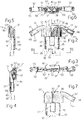
- Number 1 in Figure 1 indicates a window regulator for two-way regulation of a window 2 (shown partly by the dotted line) of a vehicle (not shown).
- Device 1 comprises a vertical channel 3; and a slide 4 connected in known and sliding manner to the curved-section main body 12 of channel 3, and in turn fitted with and supporting window 2 in known manner by means of an element 18.
- Slide 4 is moved both ways along channel 3 by a known cable activating device 5 comprising a cable 6 connected to and extending through slide 4 along a closed loop path; and an actuator assembly 8 in turn comprising a reversible electric motor 11 and connected to cable 6 so as to move it along said path.
- Cable 6 thus runs along body 12, and comes out at both ends through respective terminal elements 13 formed according to the present invention, for guiding cable 6 and which act as stops for respective ends of two sheaths 19 in which cable 6 is housed and guided along the loop path.
- the other ends of sheaths 19 are housed inside respective end portions 21 of a fixed body 20 of actuator assembly 8.
- Main body 12 which is conveniently made of sheet metal, presents, close to the ends of a bottom wall 25, two integral portions 24 cut along three sides and bent downwards, and which present holes 28 for direct fitment to a vehicle door frame (not shown).
- each terminal element 13 is formed in one piece, conveniently molded from plastic material, and is substantially T-shaped. More specifically, each terminal element 13 presents a first U-section portion 30 for connection to end portions 29 of body 12; a second upper central portion 31 which acts as a sliding and direction-change support for cable 6; and two lateral conduits 32 for housing in fixed manner one end of respective sheaths 19.
- First portion 30 is defined by a bottom wall 35 and two perpendicular lateral walls 36, which are so sized as to house perfectly a respective U-section end portion 29 of body 12 as shown clearly in Figure 6.
- the bottom wall 35 of portion 30 presents a central slot 37; and the bottom wall of end portion 29 of body 12 presents a tab 39 bent outwards so as to click on to the front end wall 40 of slot 37 ( Figures 4 and 5), when element 13 is fitted on to end portion 29 of body 12, and so prevent accidental withdrawal of element 13.
- a front end wall 41 of end portion 29 of body 12 is accordingly arrested against a vertical central front wall 43 of upper portion 31 of element 13 ( Figure 5).
- upper portion 31 presents two curved walls 45 in turn presenting a first portion 46 parallel to and adjacent to said central plane, a curved intermediate portion 47, and an end portion 48 parallel to the axis of lateral conduits 32.
- concave portions 50 extend towards the upper outer portion of portion 31, to define conduits 51 for housing cable 6 which, as only one of conduits 51 is employed, as shown in Figure 1, therefore rests on one of walls 45.
- Portions 50 define an upper slot 53 enabling insertion of cable 6 inside conduit 51.
- End portions 29 of body 12 present longer lateral walls 60 which are therefore housed in corresponding shaped portions 61 formed in upper portion 31 of element 13 and defined among other things by vertical intermediate inner walls 63 ( Figure 6).
- Lateral conduits 32 extend from end portions 48 and respective concave portions 50 of upper portion 31 of element 13, and define a larger-section tubular end portion 65 with a cylindrical inner cavity 66 also of a larger section and such as to house a respective end of a sheath 19. Lateral conduits 32 also present upper slot 53.
- Figure 7 shows a variation of element 13, indicated 13', and presenting only one lateral conduit 32.
- Element 13' must therefore be produced in two forms, specular in relation to the central plane through front wall 43, for fitment to the top or bottom portion of body 12 respectively ( Figure 1), whereas element 13 with two symmetrical lateral conduits 32 may be produced in one form for either assembly position.
- channel terminal element By virtue of a single element acting as an end stop for slide 4 on main body 12, as a sliding and direction-change support for cable 6, and as a fixed connection for one end of sheath 19, the overall cost of channel 3 is reduced and assembly simplified and made faster by eliminating additional assembly parts.
- actuator assembly 8 may comprise, in known manner, a handle as opposed to an electric motor 11.
Landscapes
- Window Of Vehicle (AREA)
Applications Claiming Priority (2)
| Application Number | Priority Date | Filing Date | Title |
|---|---|---|---|
| ITTO930593 | 1993-08-06 | ||
| ITTO930593A IT1260969B (it) | 1993-08-06 | 1993-08-06 | Elemento terminale per una guida di scorrimento per un dispositivo alzacristallo |
Publications (2)
| Publication Number | Publication Date |
|---|---|
| EP0637671A2 true EP0637671A2 (fr) | 1995-02-08 |
| EP0637671A3 EP0637671A3 (fr) | 1995-09-13 |
Family
ID=11411676
Family Applications (1)
| Application Number | Title | Priority Date | Filing Date |
|---|---|---|---|
| EP94112201A Withdrawn EP0637671A3 (fr) | 1993-08-06 | 1994-08-04 | Elément d'extrémité pour un rail de guidage tubulaire d'un lève-vitre. |
Country Status (4)
| Country | Link |
|---|---|
| EP (1) | EP0637671A3 (fr) |
| BR (1) | BR9402318A (fr) |
| IT (1) | IT1260969B (fr) |
| PL (1) | PL304576A1 (fr) |
Family Cites Families (5)
| Publication number | Priority date | Publication date | Assignee | Title |
|---|---|---|---|---|
| DE1630609A1 (de) * | 1967-07-12 | 1970-03-26 | Kuester & Co Gmbh Spezialfabri | Fensterheber zum Betaetigen der Seitenfenster von Kraftfahrzeugen |
| DE2644213B2 (de) * | 1976-09-30 | 1979-09-13 | Metallwerk Max Brose Gmbh & Co, 8630 Coburg | Gekrümmtes Umlenkglied zur Einführung des Seils eines Bowdenzüge in ein Führungsprofil eines Fensterhebers |
| GB2083132B (en) * | 1980-08-30 | 1984-08-30 | Mechanism Inventions Co | An opening and closing mechanism for windows |
| DE3152329C2 (de) * | 1981-02-13 | 1985-10-24 | Brose Fahrzeugteile GmbH & Co KG, 8630 Coburg | Fensterheber, insbesondere für Kraftfahrzeuge |
| BR6700075U (pt) * | 1987-01-20 | 1988-08-16 | Carto Metalurgica | Disposicao construtiva em mecanismo acionador de janelas de veiculos automotores |
-
1993
- 1993-08-06 IT ITTO930593A patent/IT1260969B/it active IP Right Grant
-
1994
- 1994-07-27 BR BR9402318A patent/BR9402318A/pt not_active Application Discontinuation
- 1994-08-04 EP EP94112201A patent/EP0637671A3/fr not_active Withdrawn
- 1994-08-05 PL PL94304576A patent/PL304576A1/xx unknown
Also Published As
| Publication number | Publication date |
|---|---|
| IT1260969B (it) | 1996-04-29 |
| ITTO930593A0 (it) | 1993-08-06 |
| BR9402318A (pt) | 1995-03-14 |
| ITTO930593A1 (it) | 1995-02-06 |
| EP0637671A3 (fr) | 1995-09-13 |
| PL304576A1 (en) | 1995-02-20 |
Similar Documents
| Publication | Publication Date | Title |
|---|---|---|
| US20020031322A1 (en) | Optical fiber guide device | |
| EP0596608A2 (fr) | Support de câble accessible par le côté | |
| US6049040A (en) | Universal cable guide | |
| US8075050B2 (en) | Sunroof system | |
| US4752099A (en) | Cable guide for automobile sliding roofs | |
| WO1997037099A2 (fr) | Leve-vitre comportant un ensemble coulissant ameliore | |
| EP0761994B1 (fr) | Glissière encliquetable à faible force ayant une haute force de rétention | |
| DE102004047701B4 (de) | Kabelbaumhalter und Kabelbaumverlegungsstruktur | |
| GB2365632A (en) | Wire harness slack absorbing mechanism for vehicular sliding door | |
| US4759653A (en) | Wire fixing device for window regulator | |
| EP0637671A2 (fr) | Elément d'extrémité pour un rail de guidage tubulaire d'un lève-vitre | |
| US4630398A (en) | Arrangement for lifting and lowering a windowpane, especially of a motor vehicle window | |
| US4642941A (en) | Flex drive window regulator system | |
| EP0643188B1 (fr) | Dispositif d'entraínement et de fixation pour fenêtre de véhicule | |
| US4253277A (en) | Tape drive mechanism | |
| US4335541A (en) | Window drive arrangement | |
| US20050095903A1 (en) | Take-up cassette for holding a cable of a sliding guide device and method for mounting the take-up cassette | |
| EP0744522B1 (fr) | Arbre de support à pince pour poulie | |
| US5098214A (en) | Adjustable splicing device | |
| US6189403B1 (en) | Robot arm | |
| EP1707443B1 (fr) | Dispositif d'alimentation électrique pour porte coulissante | |
| GB2034175A (en) | Windscreen wiper connecting member | |
| EP0491320B1 (fr) | Lève-vitre | |
| SE454578B (sv) | Vindavvisare for fordon med skjutbar eller hoj- och skjutbar taklucka | |
| CA2165473A1 (fr) | Leve-glaces a cable |
Legal Events
| Date | Code | Title | Description |
|---|---|---|---|
| PUAI | Public reference made under article 153(3) epc to a published international application that has entered the european phase |
Free format text: ORIGINAL CODE: 0009012 |
|
| AK | Designated contracting states |
Kind code of ref document: A2 Designated state(s): DE ES FR GB IT |
|
| K1C1 | Correction of patent application (title page) published |
Effective date: 19950208 |
|
| PUAL | Search report despatched |
Free format text: ORIGINAL CODE: 0009013 |
|
| AK | Designated contracting states |
Kind code of ref document: A3 Designated state(s): DE ES FR GB IT |
|
| 17P | Request for examination filed |
Effective date: 19960302 |
|
| 17Q | First examination report despatched |
Effective date: 19961202 |
|
| STAA | Information on the status of an ep patent application or granted ep patent |
Free format text: STATUS: THE APPLICATION IS DEEMED TO BE WITHDRAWN |
|
| 18D | Application deemed to be withdrawn |
Effective date: 19971112 |