EP0637689A2 - Wärmeleitende Beschichtung für keramische Teile eines Ionenantriebes - Google Patents
Wärmeleitende Beschichtung für keramische Teile eines Ionenantriebes Download PDFInfo
- Publication number
- EP0637689A2 EP0637689A2 EP94830374A EP94830374A EP0637689A2 EP 0637689 A2 EP0637689 A2 EP 0637689A2 EP 94830374 A EP94830374 A EP 94830374A EP 94830374 A EP94830374 A EP 94830374A EP 0637689 A2 EP0637689 A2 EP 0637689A2
- Authority
- EP
- European Patent Office
- Prior art keywords
- layer
- ionization chamber
- thermal conductivity
- thruster
- high thermal
- Prior art date
- Legal status (The legal status is an assumption and is not a legal conclusion. Google has not performed a legal analysis and makes no representation as to the accuracy of the status listed.)
- Withdrawn
Links
Images

Classifications
-
- F—MECHANICAL ENGINEERING; LIGHTING; HEATING; WEAPONS; BLASTING
- F03—MACHINES OR ENGINES FOR LIQUIDS; WIND, SPRING, OR WEIGHT MOTORS; PRODUCING MECHANICAL POWER OR A REACTIVE PROPULSIVE THRUST, NOT OTHERWISE PROVIDED FOR
- F03H—PRODUCING A REACTIVE PROPULSIVE THRUST, NOT OTHERWISE PROVIDED FOR
- F03H1/00—Using plasma to produce a reactive propulsive thrust
- F03H1/0006—Details applicable to different types of plasma thrusters
- F03H1/0031—Thermal management, heating or cooling parts of the thruster
-
- B—PERFORMING OPERATIONS; TRANSPORTING
- B64—AIRCRAFT; AVIATION; COSMONAUTICS
- B64G—COSMONAUTICS; VEHICLES OR EQUIPMENT THEREFOR
- B64G1/00—Cosmonautic vehicles
- B64G1/22—Parts of, or equipment specially adapted for fitting in or to, cosmonautic vehicles
- B64G1/40—Arrangements or adaptations of propulsion systems
- B64G1/411—Electric propulsion
- B64G1/413—Ion or plasma engines
-
- B—PERFORMING OPERATIONS; TRANSPORTING
- B64—AIRCRAFT; AVIATION; COSMONAUTICS
- B64G—COSMONAUTICS; VEHICLES OR EQUIPMENT THEREFOR
- B64G1/00—Cosmonautic vehicles
- B64G1/22—Parts of, or equipment specially adapted for fitting in or to, cosmonautic vehicles
- B64G1/226—Special coatings for spacecraft
Definitions
- the invention relates to a new method and to a new device capable of increasing the capacity for dissipation of the heat generated by the discharge inside an ion engine for space propulsion through the ceramic walls of the ionization chamber to the external environment.
- the invention is concerned with an ion thruster of the type comprising an outer supporting structure, an ionization chamber made of ceramic material, means of supplying gas to said ionization chamber, and means of ionizing the gas.
- the invention is concerned more particularly, but not exclusively, with thrusters having a ceramic coating of the acceleration channel, and based on the generation of the discharge in "Closed Electron Drift” conditions, known commercially as “Stationary Plasma Thrusters" (SPT).
- SPT Sty Plasma Thrusters
- the walls of the discharge chamber must have good thermal conductivity to avoid the presence of localized overheated areas.
- the presence of such areas would be extremely damaging to the walls, since over-heating, whether localized or widespread, limits the life of the device by causing over a short period of time the appearance of deformations, erosion of the surface of the discharge chamber, and even fracture.
- the object of the invention is to offer a more effective solution to solve the problem of heat dissipation along the ceramic walls of the discharge chamber in SPT or similar thrusters.
- the object of the invention is to provide an SPT or other thruster having a discharge chamber delimited by ceramic walls and which has high thermal shock resistance and better dissipation of the heat generated by the discharge.
- this layer of material with high thermal conductivity it is possible, on one hand, to dissipate the heat generated on the ceramic walls toward the external structure of the device and, on the other hand, to provide a uniform temperature of the ceramic material along the whole surface of the chamber in contact with the discharge, as a result of the thermal contact between the ceramic material and the highly conductive layer.
- the material with high thermal conductivity may advantageously be applied to the surfaces of the ceramic material which are not in contact with the discharge and are opposite those which delimit the chamber.
- the ionization chamber is generally delimited by an outer cylindrical wall.
- the material with high thermal conductivity may be disposed to form a coating of the whole outer cylindrical surface of the wall delimiting the ionization chamber.
- an ion thruster of the SPT type has an ionization chamber with an annular configuration delimited by two concentric cylindrical walls made of ceramic material.
- the layer of material with high thermal conductivity may be disposed on both of said walls, on the surfaces not in contact with the plasma.
- the material with high thermal conductivity may advantageously be a metallic material and in particular may consist of a laminated material, formed by successive application of metallic layers of different types.
- the invention also relates to a method for the construction of an ion thruster comprising an ionization chamber made of ceramic material, wherein a layer of material with high thermal conductivity, which is preferably disposed so that it covers the outer surface of the chamber, is disposed in contact with the ceramic material of the ionization chamber.
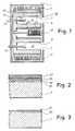
- Fig. 1 shows a highly simplified diagram of an SPT thruster, having an outer metallic structure 1, inside which is formed an annular ionization chamber 3 delimited by a block of ceramic material indicated in a general way by 5 and having two concentric cylindrical walls 7 and 9, being the outer and inner walls respectively.
- a unit with one or more coils 11 is disposed around the ionization chamber, and a second coil 13 is disposed inside the cylindrical inner wall 9.
- the ionizing discharge which is generated inside the annular chamber 3 tends to overheat the ceramic walls 7 and 9.
- the heating may be concentrated around the nozzle 17 of the thruster.
- the outer cylindrical walls of the ionization chamber are covered with a layer of metallic material. More particularly, the outer surface 19 of the cylindrical wall 7 has a metallic coating 21, while the inner surface 23 of the cylindrical wall 9 has a metallic coating 25.
- the metallic coating is formed by technologies of a type known from applications in other sectors. (H. Knoll - Materials and Process of Electron Devices. - Springer Verlag - 1959).
- Figs. 2 and 3 show a very enlarged section of a portion of the wall 7 with two different types of metallic layer applied.
- Fig. 2 shows the application by deposition on to the ceramic material of a triple metallic layer consisting of an inner layer 31 of Moly-manganese, in direct contact with the ceramic material, followed by a nickel layer 33, a copper layer 35 and an outer sheet of Cu-CuNi, indicated by 37. The various layers are welded together with an AgCu alloy.
- Fig. 3 shows an embodiment in which a metallic layer having an inner layer of chemical nickel, indicated by 39, and an outer layer of electrolytic copper, indicated by 41, is applied to the ceramic material of the wall 7.
- the metallic coating shown in Fig. 2 is vacuum-tight, while the metallic coating shown in Fig. 3 is not vacuum-tight.
- the choice may be made according to the specific requirements which may arise from time to time.
- Fig. 4 shows the application of the present invention to an ion thruster having a different structure.
- the number 3 again indicates the ionization chamber delimited by a cylindrical ceramic wall 5.
- the number 15 again indicates the gas supply means and the number 21 identifies in a general way the outer coating of material with high thermal conductivity.
- the number 51 indicates a cathode and 53 indicates an anode, between which the discharge which generates the plasma is initiated.
- the outer structural elements have been omitted, while the number 55 indicates, in a general way, ion extraction grids.
Landscapes
- Engineering & Computer Science (AREA)
- Chemical & Material Sciences (AREA)
- Combustion & Propulsion (AREA)
- Physics & Mathematics (AREA)
- Plasma & Fusion (AREA)
- Remote Sensing (AREA)
- Aviation & Aerospace Engineering (AREA)
- Mechanical Engineering (AREA)
- General Engineering & Computer Science (AREA)
- Plasma Technology (AREA)
- Ceramic Products (AREA)
Applications Claiming Priority (2)
| Application Number | Priority Date | Filing Date | Title |
|---|---|---|---|
| ITFI930159A IT1262495B (it) | 1993-08-06 | 1993-08-06 | Rivestimento conduttivo termico per ceramiche dei motori ionici |
| ITFI930159 | 1993-08-06 |
Publications (2)
| Publication Number | Publication Date |
|---|---|
| EP0637689A2 true EP0637689A2 (de) | 1995-02-08 |
| EP0637689A3 EP0637689A3 (de) | 1995-11-02 |
Family
ID=11350588
Family Applications (1)
| Application Number | Title | Priority Date | Filing Date |
|---|---|---|---|
| EP94830374A Withdrawn EP0637689A3 (de) | 1993-08-06 | 1994-07-25 | Wärmeleitende Beschichtung für keramische Teile eines Ionenantriebes. |
Country Status (3)
| Country | Link |
|---|---|
| EP (1) | EP0637689A3 (de) |
| JP (1) | JPH0771362A (de) |
| IT (1) | IT1262495B (de) |
Cited By (6)
| Publication number | Priority date | Publication date | Assignee | Title |
|---|---|---|---|---|
| RU2119095C1 (ru) * | 1997-04-10 | 1998-09-20 | Опытное конструкторское бюро "Факел" | Плазменный двигатель с замкнутым дрейфом электронов |
| US5892329A (en) * | 1997-05-23 | 1999-04-06 | International Space Technology, Inc. | Plasma accelerator with closed electron drift and conductive inserts |
| RU2139646C1 (ru) * | 1998-04-07 | 1999-10-10 | Федеральное государственное унитарное предприятие "Исследовательский центр им.М.В.Келдыша" | Плазменный ускоритель с замкнутым дрейфом электронов |
| US6075321A (en) * | 1998-06-30 | 2000-06-13 | Busek, Co., Inc. | Hall field plasma accelerator with an inner and outer anode |
| CN103945633A (zh) * | 2014-05-12 | 2014-07-23 | 重庆大学 | 一种双柱面电子直线加速器有效焦点尺寸调节装置及方法 |
| EP3219987A1 (de) * | 2016-03-17 | 2017-09-20 | Airbus DS GmbH | Entladungskammer für ein ionentriebwerk |
Families Citing this family (2)
| Publication number | Priority date | Publication date | Assignee | Title |
|---|---|---|---|---|
| FR3021301B1 (fr) * | 2014-05-21 | 2017-12-29 | Snecma | Moteur pour engin spatial, et engin spatial comprenant un tel moteur |
| JP7756356B2 (ja) * | 2021-11-19 | 2025-10-20 | 国立研究開発法人宇宙航空研究開発機構 | ホローカソード |
Family Cites Families (1)
| Publication number | Priority date | Publication date | Assignee | Title |
|---|---|---|---|---|
| US5359258A (en) * | 1991-11-04 | 1994-10-25 | Fakel Enterprise | Plasma accelerator with closed electron drift |
-
1993
- 1993-08-06 IT ITFI930159A patent/IT1262495B/it active IP Right Grant
-
1994
- 1994-07-25 EP EP94830374A patent/EP0637689A3/de not_active Withdrawn
- 1994-08-08 JP JP6186151A patent/JPH0771362A/ja active Pending
Cited By (7)
| Publication number | Priority date | Publication date | Assignee | Title |
|---|---|---|---|---|
| RU2119095C1 (ru) * | 1997-04-10 | 1998-09-20 | Опытное конструкторское бюро "Факел" | Плазменный двигатель с замкнутым дрейфом электронов |
| US5892329A (en) * | 1997-05-23 | 1999-04-06 | International Space Technology, Inc. | Plasma accelerator with closed electron drift and conductive inserts |
| RU2139646C1 (ru) * | 1998-04-07 | 1999-10-10 | Федеральное государственное унитарное предприятие "Исследовательский центр им.М.В.Келдыша" | Плазменный ускоритель с замкнутым дрейфом электронов |
| US6075321A (en) * | 1998-06-30 | 2000-06-13 | Busek, Co., Inc. | Hall field plasma accelerator with an inner and outer anode |
| CN103945633A (zh) * | 2014-05-12 | 2014-07-23 | 重庆大学 | 一种双柱面电子直线加速器有效焦点尺寸调节装置及方法 |
| CN103945633B (zh) * | 2014-05-12 | 2016-05-18 | 重庆大学 | 一种双柱面电子直线加速器有效焦点尺寸调节装置及方法 |
| EP3219987A1 (de) * | 2016-03-17 | 2017-09-20 | Airbus DS GmbH | Entladungskammer für ein ionentriebwerk |
Also Published As
| Publication number | Publication date |
|---|---|
| IT1262495B (it) | 1996-06-28 |
| ITFI930159A1 (it) | 1995-02-06 |
| JPH0771362A (ja) | 1995-03-14 |
| ITFI930159A0 (it) | 1993-08-06 |
| EP0637689A3 (de) | 1995-11-02 |
Similar Documents
| Publication | Publication Date | Title |
|---|---|---|
| US3213177A (en) | Resistance furnace | |
| JPH0771362A (ja) | イオンスラスタ及びその構造の製造方法 | |
| US3891828A (en) | Graphite-lined inert gas arc heater | |
| US20220139588A1 (en) | Nuclear battery | |
| US2407857A (en) | X-ray tube | |
| GB1562092A (en) | Electrically insulated leadthrough assembly | |
| US3453480A (en) | Electron beam production system for electronic discharge vessels | |
| EP0204541A2 (de) | Apparat mit Entladungsröhre | |
| US3449628A (en) | Plasma arc electrodes with anode heat shield | |
| JP2023075698A (ja) | ホローカソード | |
| US4772821A (en) | Apparatus for introducing oxygen gas | |
| JPH0719081Y2 (ja) | イオン源 | |
| US4801839A (en) | Mounting of a cold cathode directly to a vacuum chamber wall | |
| JPH044544A (ja) | 液冷式マグネトロン | |
| US3564318A (en) | Electrode support structure utilizing a corregated metal ribbon for accomodating thermal expansion | |
| JPS61225748A (ja) | ガスフエ−ズイオン源 | |
| KR930000337B1 (ko) | 음극 아크방전을 이용한 이온플레이팅 장치에 있어서의 아크방전 구속링 | |
| JPH06325713A (ja) | 金属イオン源 | |
| JPS5996691A (ja) | 抵抗発熱炉 | |
| JPH03237775A (ja) | 金属蒸気レーザ装置 | |
| JPH0134359Y2 (de) | ||
| JPH0745228A (ja) | カスプ磁場型イオン源装置 | |
| JPS6224537A (ja) | イオン源 | |
| JPH02304841A (ja) | ホローカソード | |
| JPH03237777A (ja) | 金属蒸気レーザ装置 |
Legal Events
| Date | Code | Title | Description |
|---|---|---|---|
| PUAI | Public reference made under article 153(3) epc to a published international application that has entered the european phase |
Free format text: ORIGINAL CODE: 0009012 |
|
| AK | Designated contracting states |
Kind code of ref document: A2 Designated state(s): AT BE CH DE DK ES FR GB GR IE LI LU MC NL PT SE |
|
| PUAL | Search report despatched |
Free format text: ORIGINAL CODE: 0009013 |
|
| AK | Designated contracting states |
Kind code of ref document: A3 Designated state(s): AT BE CH DE DK ES FR GB GR IE LI LU MC NL PT SE |
|
| STAA | Information on the status of an ep patent application or granted ep patent |
Free format text: STATUS: THE APPLICATION IS DEEMED TO BE WITHDRAWN |
|
| 18D | Application deemed to be withdrawn |
Effective date: 19960503 |