EP0638468A1 - Accouplement pour transmettre le mouvement du câble de traction d'un tendeur à la bobine d'un enrouleur de ceinture de sécurité - Google Patents
Accouplement pour transmettre le mouvement du câble de traction d'un tendeur à la bobine d'un enrouleur de ceinture de sécurité Download PDFInfo
- Publication number
- EP0638468A1 EP0638468A1 EP94112518A EP94112518A EP0638468A1 EP 0638468 A1 EP0638468 A1 EP 0638468A1 EP 94112518 A EP94112518 A EP 94112518A EP 94112518 A EP94112518 A EP 94112518A EP 0638468 A1 EP0638468 A1 EP 0638468A1
- Authority
- EP
- European Patent Office
- Prior art keywords
- coupling according
- movement
- clutch disc
- coupling
- driving
- Prior art date
- Legal status (The legal status is an assumption and is not a legal conclusion. Google has not performed a legal analysis and makes no representation as to the accuracy of the status listed.)
- Granted
Links
- 230000008878 coupling Effects 0.000 title claims abstract description 46
- 238000010168 coupling process Methods 0.000 title claims abstract description 46
- 238000005859 coupling reaction Methods 0.000 title claims abstract description 46
- 230000000903 blocking effect Effects 0.000 claims description 23
- 239000000463 material Substances 0.000 claims description 3
- 230000001960 triggered effect Effects 0.000 description 7
- 238000004804 winding Methods 0.000 description 6
- 238000010008 shearing Methods 0.000 description 4
- 230000000694 effects Effects 0.000 description 3
- 230000001404 mediated effect Effects 0.000 description 2
- 229910000831 Steel Inorganic materials 0.000 description 1
- 230000005540 biological transmission Effects 0.000 description 1
- 210000003464 cuspid Anatomy 0.000 description 1
- 238000000034 method Methods 0.000 description 1
- 239000007779 soft material Substances 0.000 description 1
- 239000010959 steel Substances 0.000 description 1
Images


Classifications
-
- B—PERFORMING OPERATIONS; TRANSPORTING
- B60—VEHICLES IN GENERAL
- B60R—VEHICLES, VEHICLE FITTINGS, OR VEHICLE PARTS, NOT OTHERWISE PROVIDED FOR
- B60R22/00—Safety belts or body harnesses in vehicles
- B60R22/34—Belt retractors, e.g. reels
- B60R22/46—Reels with means to tension the belt in an emergency by forced winding up
- B60R22/4619—Transmission of tensioning power by cable, e.g. using a clutch on reel side
-
- B—PERFORMING OPERATIONS; TRANSPORTING
- B60—VEHICLES IN GENERAL
- B60R—VEHICLES, VEHICLE FITTINGS, OR VEHICLE PARTS, NOT OTHERWISE PROVIDED FOR
- B60R22/00—Safety belts or body harnesses in vehicles
- B60R22/34—Belt retractors, e.g. reels
-
- B—PERFORMING OPERATIONS; TRANSPORTING
- B60—VEHICLES IN GENERAL
- B60R—VEHICLES, VEHICLE FITTINGS, OR VEHICLE PARTS, NOT OTHERWISE PROVIDED FOR
- B60R22/00—Safety belts or body harnesses in vehicles
- B60R22/34—Belt retractors, e.g. reels
- B60R22/46—Reels with means to tension the belt in an emergency by forced winding up
- B60R2022/468—Reels with means to tension the belt in an emergency by forced winding up characterised by clutching means between actuator and belt reel
Definitions
- the invention relates to a clutch for transmitting the back tensioning movement acting on a pull rope to a belt reel of a seat belt retractor with a clutch disc which is connected to the pull rope and a driving device which, when the pull rope is moved, connects the clutch disc to the belt reel in a rotationally fixed manner, one caused by the pull rope movement Rotation of the clutch disc is transmitted to the coil.
- the back tensioning movement eliminates a belt looseness in the belt webbing, which lies against the vehicle occupant, or loosely wound belt webbing layers on the belt webbing reel, which can lead to a film reel effect.
- the back tensioning movement is generated by a conventional belt tensioner (e.g. EP 0 529 501 A1).
- the object of the invention is to provide a clutch of the type mentioned at the outset, with which the belt tensioner movement is transmitted to the belt reel with effective transmission of the forces exerted by the pull rope.
- the clutch disc and the driving device are held together with the belt reel in normal operation in a normal position in which the belt reel can rotate freely.
- the clutch disc on the frame of the automatic reel-up or on a clutch housing connected to the frame is locked against rotation.
- the locking device effective between the clutch disc and the frame or the clutch housing is released by the force exerted by the moving pull cable.
- the locking device can be designed as a locking pin which is sheared off by the lifting cable movement. Due to the radially outwardly moving driver elements, an improved torque is transmitted to the belt reel from the clutch disc rotated by the traction cable.
- the movement of the pull cable can be converted into a rotary movement of the clutch disc.
- a pre-blocking element comes into engagement with the spool, so that it is blocked against rotation during the subsequent pulling rope movement, which serves to tighten the belt.
- the pre-blocking element can be designed as a lever supported on the frame or on the clutch housing.
- the pull rope movement is used to take entrainment elements into a radially outer engagement position to bring with the coil so that the clutch disc and the coil are rotatably connected together.
- the driving elements which can be designed as clamping jaws or the like, can be slidably mounted on the clutch disc.
- the entrainment elements are mounted at equal angular distances from one another about a common axis of rotation about which the clutch disc, the coil and the entire entrainment device can be rotated.
- one entrainment element can also be provided.
- the driver elements can have control surfaces which are guided along control elements, which are held stationary during their movement in their engagement positions with respect to the clutch housing or the frame of the automatic belt retractor.
- a second locking device for example in the form of a further shear pin, which acts between the clutch disk and the control elements, can be released after the first locking device is released.
- the control elements which can be attached to a common control part, are held on the clutch housing or on the frame for their fixed positioning by means of a third locking device. If the non-rotatable connection between the clutch disc and the coil is connected in a rotationally fixed manner via the driving device, the control elements are released from their engagement with the driving element or the driving elements. This can be done in that a third locking device, with which the control part, to which the control elements are attached, locks in a stationary manner on the clutch housing or frame is resolved.
- This locking device can also be designed as a shear pin, which is sheared off by the forces transmitted during the traction cable movement via the clutch disc, the driving device and the control part.
- the driving elements In their final engagement position with the coil, the driving elements can assume such a position that they are moved past the stationary control elements, which are preferably provided on the clutch housing.
- the traction cable movement can also be used in such a way that a flexible ratchet or a similar acoustic signal generator can be brought into engagement with a toothing which is connected to the spool in a rotationally fixed manner. In this way, a false triggering of the belt tensioner is indicated, so that the belt tensioner can be replaced by a new belt tensioner with a loaded energy accumulator.
- the use of an acoustic signal transmitter for example in the form of a flexible ratchet of the type described, can also be used in such couplings in which the pulling cable movement is transmitted to coils with a fixed axis position in the frame.
- the clutch disc and the driving device can be movable with the lifting movement with which the belt reel is moved into the blocking position. This applies both in the event that the belt reel due to an excessive change in vehicle speed (crash case) is moved into the blocking position, as well as in the event that the belt reel is moved as a precaution into the blocking position and returns from there to the normal position.
- the locking device can then be pivotally mounted on the frame or on the clutch housing, so that it enables the lifting movement of the clutch disc and the driving device in normal operation.
- An automatic lifting roller in which the invention can be used, is known, for example, from German Patent 37 11 537.
- the lifting roller movement is a rotational movement which takes place about a pivot axis lying outside the spool.
- the pivot point or the pivot axis for the locking device is then close to the pivot axis of the stroke movement of the coil.
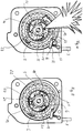
- the clutch shown in the figures has a clutch disc 2.
- the clutch disc 2 is rotatable about a common axis 18 with a belt reel 1 of an automatic seat belt retractor, which is designed as an automatic lifting roller.
- Such an automatic lifting roller is known from German Patent 37 11 537.
- the spool 1 and the clutch disc 2 are rotatably mounted on a bearing leg 15 of a U-shaped bearing needle 26. This arrangement is in turn pivoted about an axis of rotation formed by a bearing leg 17 for a rotational movement about this axis.
- the coil can be moved between a normal position in which the coil is freely rotatable and a blocking position in which blocking teeth 23 and 24 on the coil engage in corresponding blocking teeth 27 and 28 on the frame 8.
- end Housing caps 30 and 35 the belt retractor is closed to the outside. With 29 an end plate is designated.
- a tension cable 3 is connected to the clutch disc 2 and transmits the belt tensioner movement of a belt tensioner, not shown, to the clutch disc 2.
- the cable 3 is wound in a known manner on a correspondingly designed winding part of the clutch disc.
- the pull cable 3 can be wound onto the clutch disc in the manner known from EP 0 529 265 A1.
- a spiral cable guide is used on the clutch disc. This ensures that the belt tensioner movement 3 is converted into a rotational movement of the clutch disc 2.
- a driving device which can establish a rotationally fixed connection between the clutch disc 2 and the coil 1.
- This driving device has slidably mounted driving elements 4 on the clutch disc 2, which are designed as gripper jaws.
- the driving elements 4 are slidably mounted on bearing jaws 7 of the clutch disc 2.
- the driving elements 4 have outward-facing serrations 19 which can come into non-positive engagement with the inside of a driving ring 20 which is connected to the coil 1 in a rotationally fixed manner.
- This frictional connection can be produced by positive or frictional engagement.
- control part 5 is provided, on the circumference of which control elements 6 are provided.
- control elements 6 are arranged at equal angular distances from one another about the common axis 18 or the bearing leg 15.
- three driving elements 4 and three associated control elements 6 are provided in the form of control pins.
- Control surfaces 11 are provided on the driving elements 4.
- the control surfaces 11 are guided along the control pins.
- the driving elements 4 are held in their normal position by a positioning plate 34, for example by frictional force between the positioning plate 34 and the clutch disc 2.
- the first locking device 10 is formed by a pin provided on a lever 12. This pin locks the clutch disc 2 on the frame 8 or on a clutch housing 9, which, as shown in FIG. 1, is provided between the front cover 30 and the frame 8.
- the clutch housing 9 is rigidly connected to the frame 8.
- the lever 12 is pivotally mounted about a pivot axis 16 on the frame 8 or coupling housing 9. In this normal position, due to the pivotable guidance of the locking device 10 (locking pin) about the pivot axis 16, the clutch disc 2 together with the coil 1 can pivot movements between that in FIG. 2 carry out the normal position shown and a blocking position.
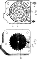
- the drive device of the belt tensioner is triggered and the pull rope 3 performs a tensioning movement shown in FIG. 2.
- the movement of the pull cable 3 in the direction of the arrow shown in FIG. 2 affects the clutch disc 2 and sets it in rotation.
- the locking device 10 which is designed as a pin, is sheared off and the lever, which is pretensioned by a spring 31 and forms a pre-blocking element 12, is brought into an engaged position, as shown in FIG. 4 , in which it engages in the main locking toothing 23 of the coil 1.
- This pre-blocking prevents the spool from rotating in the opposite direction to the pull-rope pull-out direction.
- the further rotation of the clutch disc 2 shears off a second locking device 13 in the form of a shear pin which, in the normal position (FIG. 2), acts between a control part 5 and the clutch disc 2, for example on a bearing jaw 7 fastened to the clutch disc 2.
- the control part 5 with the control elements 6 attached to it is locked by a third locking device 14 with respect to the frame 8 or the clutch housing 9.
- the control part 5 is supported by a control lever 32 (FIG. 4) on the pin acting as a lock 14, which allows the stroke movement by a Recess 43 in the clutch disc 2 protrudes.
- a precise positioning of the control part 5 and the control elements 6 attached to it is ensured by the pin which is positioned exactly in the clutch housing 9 or in the frame 8 and forms the third locking device 14. This also ensures that the driving elements with their control surfaces 11 run along the control elements 6 4 come into engagement with the internal toothing of the driving ring 20. In particular, a first engagement of the catch tooth 21 in one of the teeth on the inside of the driving ring 20 is ensured. The control of the engagement of the remaining teeth in the respective toothings 19 in the inner toothing 22 of the driving ring 20 then takes place automatically when the clutch disc 2 continues to rotate, the control surfaces 11 then being removed from the control elements 6. As a result, the rotationally fixed connection between the clutch disc 2 and the coil 1 is established (FIG. 6).
- the locking pin 14 can be sheared off by the control lever 32 by the rotation of the control part 5, as is shown in FIG. 7.
- the clutch disc 2 and the control part 5 can rotate freely and are rotated in the direction of an arrow A in FIG. 8 by the belt tensioner movement mediated by the pull rope, so that the belt webbing against the webbing extension direction from the coiled spool 1 in the machine in the direction of an arrow B is drawn in Fig. 8.
- Belt layers lying loosely on the spool are also tightened to avoid a film spool effect. This process takes place before the coil 1 is pivoted from its normal position into the blocking position, in which the blocking toothings 23 and 24 of the coil come into blocking engagement with the frame-side toothings 27 and 28.
- the driving ring 20 can be designed in such a way that it has an internal ring part, which consists of a softer material than the material of the driving elements 4. This ensures that that the driving elements 4 with their respective serrations 19 dig into the soft material and thus produce a perfect frictional connection between the clutch disc 2 and the coil 1.
- the inner ring part is surrounded by a hard, for example made of steel, outer ring part on the driving ring 20, so that a counter bearing for the driving force is formed.
- FIG. 9 shows a flexible ratchet which is brought into an engagement position shown in FIG. 9 by a toothing which is connected to the spool 1 in a rotationally fixed manner by means of the pull cable 3 which is moved in a belt tensioning movement.
- this is, for example, the main locking toothing 23 on the spool 1. This results in an acoustic signal generator which indicates that the belt tensioner has been triggered.
- the vehicle occupant will be triggered by the acoustic signal when actuating, in particular when putting on and taking off the seat belt Belt tensioners displayed so that he is prompted for a workshop trip.
- FIG. 10 shows an exploded perspective view of modified coupling parts for an automatic belt retractor with a fixed winding shaft axis 18.
- the winding shaft axis or common axis for the clutch disc 2 and the belt reel 1 is formed by the bearing leg 15 the U-shaped bearing needle.
- this U-shaped bearing needle is prevented from pivoting by recesses 36 and 37 in the end housing caps 30 and 35, so that the bearing leg 15 forms a fixed axis for the belt reel 1 and the clutch disc 2.
- control elements 33 are provided, which are provided in a stationary manner on the clutch housing 9 on an axially extending sleeve 38. These control elements 33 come into engagement with the control surfaces 11 on the driving elements 4 when these are brought outward into the engagement position with the driving ring 20.
- a further fixing web 39 is provided, which comes into engagement with the two ends of the U-shaped bearing needle and is fixed in the already mentioned recess 36 of the housing cap 35.
- a webbing-sensitive and vehicle-sensitive sensor device 40 designed in a known manner acts on locking pawls 41, 42 which are supported on the frame 8 and which can come into engagement with the blocking teeth 23 and 24 on the spool 1. This intervention occurs when 3 loose webbing layers - as already explained - are removed by the pull rope.
- the pawls are actuated independently of the sensor device.
- the pawl 41, 42 held by a resilient holding part 43 in the rest position. In this rest position, the pawl is out of engagement with the blocking teeth or with the blocking teeth 23, 24 of the belt spool 1.
- An actuating part 44 is used to actuate the pawl 41, 42. This actuating part 44 is under the pretension of a spring 45. The springs 45 and the actuating part 44 are also held in the rest position in the illustration in FIG. 11. This is achieved by a retaining pin 46.
- the retaining pin 46 is designed as a shear pin and can be sheared off by a component 47 which is moved when the seat belt is tightened.
- the component 47 can be molded onto the clutch disc 2 and acts as a shearing element for the retaining pin 46.
- the actuating part 44 can act on the pawl 41, 42 via an intermediate lever 48.
- a common holding ring 49 for example made of plastic, is provided for positioning.
- This retaining ring 49 is inserted into the housing 9.
- the holding ring 49 can be fastened to the housing 9 with the aid of a fastening pin 50.
- the holding pin 46 can also be on the housing 9 for holding the spring 45 and the actuating part 44 can be fixed in their rest position.
- the pawls 41, 42 are pressed into the blocking teeth 23, 24 by the pretensioning of the spring 45, the pawls ratchet on the teeth 23, 24 when the belt reel 1 is rotated during the further Tight movement.
- the pawls 41, 42 come into their final locking position with the toothings 23, 24 on the sides of the belt reel 1 when this rotational movement is reversed.
Landscapes
- Engineering & Computer Science (AREA)
- Mechanical Engineering (AREA)
- Automotive Seat Belt Assembly (AREA)
- Flexible Shafts (AREA)
Applications Claiming Priority (2)
| Application Number | Priority Date | Filing Date | Title |
|---|---|---|---|
| DE4327134 | 1993-08-12 | ||
| DE4327134A DE4327134A1 (de) | 1993-08-12 | 1993-08-12 | Kupplung zum Übertragen der auf ein Zugseil wirkenden Rückstrafferbewegung auf eine Gurtbandspule eines Sicherheitsgurtaufrollautomaten |
Publications (2)
| Publication Number | Publication Date |
|---|---|
| EP0638468A1 true EP0638468A1 (fr) | 1995-02-15 |
| EP0638468B1 EP0638468B1 (fr) | 1998-04-22 |
Family
ID=6495053
Family Applications (1)
| Application Number | Title | Priority Date | Filing Date |
|---|---|---|---|
| EP94112518A Expired - Lifetime EP0638468B1 (fr) | 1993-08-12 | 1994-08-10 | Accouplement pour transmettre le mouvement du câble de traction d'un tendeur à la bobine d'un enrouleur de ceinture de sécurité |
Country Status (4)
| Country | Link |
|---|---|
| EP (1) | EP0638468B1 (fr) |
| AT (1) | ATE165290T1 (fr) |
| DE (2) | DE4327134A1 (fr) |
| ES (1) | ES2115823T3 (fr) |
Cited By (4)
| Publication number | Priority date | Publication date | Assignee | Title |
|---|---|---|---|---|
| EP0729868A3 (fr) * | 1995-02-01 | 1997-01-08 | Takata Europ Gmbh | Dispositif de ceinture de sécurité pour véhicules avec un tendeur de ceinture |
| DE19609524A1 (de) * | 1996-03-11 | 1997-09-18 | Autoliv Dev | Gurtaufroller-Gurtstrammer-Kombination mit Kraftbegrenzer |
| GB2397492A (en) * | 2003-01-24 | 2004-07-28 | Kraft Foods R & D Inc | Beverage cartridge with provision for the production of a jet of beverage |
| CN113552404A (zh) * | 2021-07-20 | 2021-10-26 | 中国神华能源股份有限公司哈尔乌素露天煤矿 | 一种电缆卷放车保护监控方法、系统及存储介质 |
Families Citing this family (1)
| Publication number | Priority date | Publication date | Assignee | Title |
|---|---|---|---|---|
| DE19621772C1 (de) * | 1996-05-30 | 1997-04-10 | Hs Tech & Design | Gurtstraffer für einen Sicherheitsgurt |
Citations (6)
| Publication number | Priority date | Publication date | Assignee | Title |
|---|---|---|---|---|
| FR2615150A1 (fr) * | 1987-05-12 | 1988-11-18 | Trw Repa Gmbh | Enrouleur de ceinture de securite avec dispositif de tension |
| EP0313098A1 (fr) * | 1987-10-23 | 1989-04-26 | Autoliv-Kolb GmbH & Co. | Dispositif tendeur pour ceinture de sécurité |
| DE8600002U1 (de) * | 1986-01-02 | 1989-05-03 | Trw Repa Gmbh, 73553 Alfdorf | Rotations-Gurtstraffer für Sicherheitsgurte |
| GB2216776A (en) * | 1988-03-29 | 1989-10-18 | Trw Repa Gmbh | Vehicle safety belt tightening device |
| US4925212A (en) * | 1988-04-19 | 1990-05-15 | Honda Giken Kogyo Kabushiki Kaisha | Seat belt tightening system adapted to be mounted on an adjustable seat |
| EP0600689A1 (fr) * | 1992-12-02 | 1994-06-08 | Alliedsignal Limited | Rétracteur de ceinture de sécurité à prétensionneur |
-
1993
- 1993-08-12 DE DE4327134A patent/DE4327134A1/de not_active Withdrawn
-
1994
- 1994-08-10 AT AT94112518T patent/ATE165290T1/de active
- 1994-08-10 EP EP94112518A patent/EP0638468B1/fr not_active Expired - Lifetime
- 1994-08-10 ES ES94112518T patent/ES2115823T3/es not_active Expired - Lifetime
- 1994-08-10 DE DE59405763T patent/DE59405763D1/de not_active Expired - Fee Related
Patent Citations (6)
| Publication number | Priority date | Publication date | Assignee | Title |
|---|---|---|---|---|
| DE8600002U1 (de) * | 1986-01-02 | 1989-05-03 | Trw Repa Gmbh, 73553 Alfdorf | Rotations-Gurtstraffer für Sicherheitsgurte |
| FR2615150A1 (fr) * | 1987-05-12 | 1988-11-18 | Trw Repa Gmbh | Enrouleur de ceinture de securite avec dispositif de tension |
| EP0313098A1 (fr) * | 1987-10-23 | 1989-04-26 | Autoliv-Kolb GmbH & Co. | Dispositif tendeur pour ceinture de sécurité |
| GB2216776A (en) * | 1988-03-29 | 1989-10-18 | Trw Repa Gmbh | Vehicle safety belt tightening device |
| US4925212A (en) * | 1988-04-19 | 1990-05-15 | Honda Giken Kogyo Kabushiki Kaisha | Seat belt tightening system adapted to be mounted on an adjustable seat |
| EP0600689A1 (fr) * | 1992-12-02 | 1994-06-08 | Alliedsignal Limited | Rétracteur de ceinture de sécurité à prétensionneur |
Cited By (7)
| Publication number | Priority date | Publication date | Assignee | Title |
|---|---|---|---|---|
| EP0729868A3 (fr) * | 1995-02-01 | 1997-01-08 | Takata Europ Gmbh | Dispositif de ceinture de sécurité pour véhicules avec un tendeur de ceinture |
| US5743480A (en) * | 1995-02-01 | 1998-04-28 | Takata (Europe) Vehicle Safety Technology Gmbh | Safety belt arrangement in motor vehicles having a belt tensioner |
| DE19609524A1 (de) * | 1996-03-11 | 1997-09-18 | Autoliv Dev | Gurtaufroller-Gurtstrammer-Kombination mit Kraftbegrenzer |
| DE19609524C2 (de) * | 1996-03-11 | 2000-06-08 | Autoliv Dev | Gurtaufroller-Gurtstrammer-Kombination mit Kraftbegrenzer |
| GB2397492A (en) * | 2003-01-24 | 2004-07-28 | Kraft Foods R & D Inc | Beverage cartridge with provision for the production of a jet of beverage |
| GB2397492B (en) * | 2003-01-24 | 2005-10-12 | Kraft Foods R & D Inc | Cartridge for the preparation of beverages |
| CN113552404A (zh) * | 2021-07-20 | 2021-10-26 | 中国神华能源股份有限公司哈尔乌素露天煤矿 | 一种电缆卷放车保护监控方法、系统及存储介质 |
Also Published As
| Publication number | Publication date |
|---|---|
| DE4327134A1 (de) | 1995-02-16 |
| ATE165290T1 (de) | 1998-05-15 |
| DE59405763D1 (de) | 1998-05-28 |
| ES2115823T3 (es) | 1998-07-01 |
| EP0638468B1 (fr) | 1998-04-22 |
Similar Documents
| Publication | Publication Date | Title |
|---|---|---|
| DE4345457C2 (de) | Gurtaufroller-Gurtstrammer-Kombination mit Kraftbegrenzer | |
| DE60129755T2 (de) | Sicherheitsgurt-Retraktor | |
| DE60010417T2 (de) | Sicherheitsgurt-Retraktor | |
| DE10020245C2 (de) | Gurtaufroller für einen Fahrzeugsicherheitsgurt | |
| DE19528115A1 (de) | Gurtaufroller mit in einem Drehweg begrenzten Kraftbegrenzer | |
| WO1997033778A1 (fr) | Systeme combine pour enrouler et tendre une ceinture, muni d'un limiteur de force | |
| DE10213906A1 (de) | Leistungsstraffer | |
| DE4227781C2 (de) | Gurtaufroller mit an der Gurtspule angreifendem Gurtstraffer | |
| DE19758495A1 (de) | Sicherheitsgurtaufroller | |
| DE10204475B4 (de) | Gurtstraffer | |
| DE10013869C2 (de) | Komfort-Aufwickeleinrichtung für einen Sicherheitsgurt mit Motorrückholung | |
| DE2803874C2 (de) | Vorrichtung zum Rückholen und Aufrollen eines Sicherheitsgurtes | |
| DE10024344A1 (de) | Kupplungsmechanismus | |
| DE3621622A1 (de) | Gurtstraffer an einem sicherheitsgurtaufroller | |
| EP2944520B1 (fr) | Enrouleur de ceinture pour une ceinture de sécurité de véhicule | |
| EP1723013B1 (fr) | Pretensionneur de ceinture de securite | |
| EP1656286B1 (fr) | Enrouleur de ceinture | |
| DE69914842T2 (de) | Kupplungsvorrichtung zur Drehmomentübertragung | |
| EP0638468B1 (fr) | Accouplement pour transmettre le mouvement du câble de traction d'un tendeur à la bobine d'un enrouleur de ceinture de sécurité | |
| DE19727083C2 (de) | Sitzgurtaufroller mit Energieabsorption | |
| DE4242814A1 (fr) | ||
| DE10101048A1 (de) | Sicherheitsgurtvorrichtung | |
| DE102019203356B4 (de) | Reversibler Gurtstraffer für einen Sicherheitsgurt | |
| EP0778182A2 (fr) | Système de retenue dans un véhicule | |
| DE19544918A1 (de) | Sicherheitsgurtaufroller |
Legal Events
| Date | Code | Title | Description |
|---|---|---|---|
| PUAI | Public reference made under article 153(3) epc to a published international application that has entered the european phase |
Free format text: ORIGINAL CODE: 0009012 |
|
| AK | Designated contracting states |
Kind code of ref document: A1 Designated state(s): AT DE ES FR GB IT NL SE |
|
| 17P | Request for examination filed |
Effective date: 19950627 |
|
| 17Q | First examination report despatched |
Effective date: 19960812 |
|
| GRAG | Despatch of communication of intention to grant |
Free format text: ORIGINAL CODE: EPIDOS AGRA |
|
| GRAG | Despatch of communication of intention to grant |
Free format text: ORIGINAL CODE: EPIDOS AGRA |
|
| GRAH | Despatch of communication of intention to grant a patent |
Free format text: ORIGINAL CODE: EPIDOS IGRA |
|
| GRAH | Despatch of communication of intention to grant a patent |
Free format text: ORIGINAL CODE: EPIDOS IGRA |
|
| GRAA | (expected) grant |
Free format text: ORIGINAL CODE: 0009210 |
|
| AK | Designated contracting states |
Kind code of ref document: B1 Designated state(s): AT DE ES FR GB IT NL SE |
|
| PG25 | Lapsed in a contracting state [announced via postgrant information from national office to epo] |
Ref country code: NL Free format text: LAPSE BECAUSE OF FAILURE TO SUBMIT A TRANSLATION OF THE DESCRIPTION OR TO PAY THE FEE WITHIN THE PRESCRIBED TIME-LIMIT Effective date: 19980422 |
|
| REF | Corresponds to: |
Ref document number: 165290 Country of ref document: AT Date of ref document: 19980515 Kind code of ref document: T |
|
| GBT | Gb: translation of ep patent filed (gb section 77(6)(a)/1977) |
Effective date: 19980423 |
|
| REF | Corresponds to: |
Ref document number: 59405763 Country of ref document: DE Date of ref document: 19980528 |
|
| ITF | It: translation for a ep patent filed | ||
| RAP2 | Party data changed (patent owner data changed or rights of a patent transferred) |
Owner name: BREED AUTOMOTIVE TECHNOLOGY, INC. |
|
| ET | Fr: translation filed | ||
| REG | Reference to a national code |
Ref country code: ES Ref legal event code: FG2A Ref document number: 2115823 Country of ref document: ES Kind code of ref document: T3 |
|
| PG25 | Lapsed in a contracting state [announced via postgrant information from national office to epo] |
Ref country code: SE Free format text: LAPSE BECAUSE OF FAILURE TO SUBMIT A TRANSLATION OF THE DESCRIPTION OR TO PAY THE FEE WITHIN THE PRESCRIBED TIME-LIMIT Effective date: 19980722 |
|
| NLT2 | Nl: modifications (of names), taken from the european patent patent bulletin |
Owner name: BREED AUTOMOTIVE TECHNOLOGY, INC. |
|
| PG25 | Lapsed in a contracting state [announced via postgrant information from national office to epo] |
Ref country code: AT Free format text: LAPSE BECAUSE OF NON-PAYMENT OF DUE FEES Effective date: 19980810 |
|
| NLV1 | Nl: lapsed or annulled due to failure to fulfill the requirements of art. 29p and 29m of the patents act | ||
| PLBE | No opposition filed within time limit |
Free format text: ORIGINAL CODE: 0009261 |
|
| STAA | Information on the status of an ep patent application or granted ep patent |
Free format text: STATUS: NO OPPOSITION FILED WITHIN TIME LIMIT |
|
| 26N | No opposition filed | ||
| PGFP | Annual fee paid to national office [announced via postgrant information from national office to epo] |
Ref country code: FR Payment date: 20000803 Year of fee payment: 7 |
|
| PGFP | Annual fee paid to national office [announced via postgrant information from national office to epo] |
Ref country code: ES Payment date: 20000816 Year of fee payment: 7 |
|
| PG25 | Lapsed in a contracting state [announced via postgrant information from national office to epo] |
Ref country code: ES Free format text: LAPSE BECAUSE OF NON-PAYMENT OF DUE FEES Effective date: 20010811 |
|
| REG | Reference to a national code |
Ref country code: GB Ref legal event code: IF02 |
|
| PG25 | Lapsed in a contracting state [announced via postgrant information from national office to epo] |
Ref country code: FR Free format text: LAPSE BECAUSE OF NON-PAYMENT OF DUE FEES Effective date: 20020430 |
|
| REG | Reference to a national code |
Ref country code: FR Ref legal event code: ST |
|
| PGFP | Annual fee paid to national office [announced via postgrant information from national office to epo] |
Ref country code: GB Payment date: 20020626 Year of fee payment: 9 |
|
| PGFP | Annual fee paid to national office [announced via postgrant information from national office to epo] |
Ref country code: DE Payment date: 20020830 Year of fee payment: 9 |
|
| REG | Reference to a national code |
Ref country code: GB Ref legal event code: 732E |
|
| PG25 | Lapsed in a contracting state [announced via postgrant information from national office to epo] |
Ref country code: GB Free format text: LAPSE BECAUSE OF NON-PAYMENT OF DUE FEES Effective date: 20030810 |
|
| PG25 | Lapsed in a contracting state [announced via postgrant information from national office to epo] |
Ref country code: DE Free format text: LAPSE BECAUSE OF NON-PAYMENT OF DUE FEES Effective date: 20040302 |
|
| GBPC | Gb: european patent ceased through non-payment of renewal fee |
Effective date: 20030810 |
|
| REG | Reference to a national code |
Ref country code: ES Ref legal event code: FD2A Effective date: 20020911 |
|
| PG25 | Lapsed in a contracting state [announced via postgrant information from national office to epo] |
Ref country code: IT Free format text: LAPSE BECAUSE OF NON-PAYMENT OF DUE FEES;WARNING: LAPSES OF ITALIAN PATENTS WITH EFFECTIVE DATE BEFORE 2007 MAY HAVE OCCURRED AT ANY TIME BEFORE 2007. THE CORRECT EFFECTIVE DATE MAY BE DIFFERENT FROM THE ONE RECORDED. Effective date: 20050810 |