EP0638468B1 - Accouplement pour transmettre le mouvement du câble de traction d'un tendeur à la bobine d'un enrouleur de ceinture de sécurité - Google Patents
Accouplement pour transmettre le mouvement du câble de traction d'un tendeur à la bobine d'un enrouleur de ceinture de sécurité Download PDFInfo
- Publication number
- EP0638468B1 EP0638468B1 EP94112518A EP94112518A EP0638468B1 EP 0638468 B1 EP0638468 B1 EP 0638468B1 EP 94112518 A EP94112518 A EP 94112518A EP 94112518 A EP94112518 A EP 94112518A EP 0638468 B1 EP0638468 B1 EP 0638468B1
- Authority
- EP
- European Patent Office
- Prior art keywords
- coupling
- movement
- coupling according
- spool
- locking
- Prior art date
- Legal status (The legal status is an assumption and is not a legal conclusion. Google has not performed a legal analysis and makes no representation as to the accuracy of the status listed.)
- Expired - Lifetime
Links
- 230000008878 coupling Effects 0.000 title claims abstract description 63
- 238000010168 coupling process Methods 0.000 title claims abstract description 63
- 238000005859 coupling reaction Methods 0.000 title claims abstract description 63
- 230000033001 locomotion Effects 0.000 title claims abstract description 59
- 239000000463 material Substances 0.000 claims description 3
- 238000006073 displacement reaction Methods 0.000 claims 1
- 230000000903 blocking effect Effects 0.000 description 14
- 230000001960 triggered effect Effects 0.000 description 8
- 238000004804 winding Methods 0.000 description 6
- 230000000694 effects Effects 0.000 description 5
- 230000005540 biological transmission Effects 0.000 description 4
- 230000001404 mediated effect Effects 0.000 description 2
- 238000010008 shearing Methods 0.000 description 2
- 229910000831 Steel Inorganic materials 0.000 description 1
- 210000003464 cuspid Anatomy 0.000 description 1
- 239000007779 soft material Substances 0.000 description 1
- 239000010959 steel Substances 0.000 description 1
Images


Classifications
-
- B—PERFORMING OPERATIONS; TRANSPORTING
- B60—VEHICLES IN GENERAL
- B60R—VEHICLES, VEHICLE FITTINGS, OR VEHICLE PARTS, NOT OTHERWISE PROVIDED FOR
- B60R22/00—Safety belts or body harnesses in vehicles
- B60R22/34—Belt retractors, e.g. reels
- B60R22/46—Reels with means to tension the belt in an emergency by forced winding up
- B60R22/4619—Transmission of tensioning power by cable, e.g. using a clutch on reel side
-
- B—PERFORMING OPERATIONS; TRANSPORTING
- B60—VEHICLES IN GENERAL
- B60R—VEHICLES, VEHICLE FITTINGS, OR VEHICLE PARTS, NOT OTHERWISE PROVIDED FOR
- B60R22/00—Safety belts or body harnesses in vehicles
- B60R22/34—Belt retractors, e.g. reels
-
- B—PERFORMING OPERATIONS; TRANSPORTING
- B60—VEHICLES IN GENERAL
- B60R—VEHICLES, VEHICLE FITTINGS, OR VEHICLE PARTS, NOT OTHERWISE PROVIDED FOR
- B60R22/00—Safety belts or body harnesses in vehicles
- B60R22/34—Belt retractors, e.g. reels
- B60R22/46—Reels with means to tension the belt in an emergency by forced winding up
- B60R2022/468—Reels with means to tension the belt in an emergency by forced winding up characterised by clutching means between actuator and belt reel
Definitions
- the invention relates to a coupling for transmission the back tension movement acting on a pull rope on a belt reel of a seat belt retractor with a clutch disc, which with the Pull rope is connected and a driving device, which, when the traction cable is moved, the clutch disc non-rotatably connects to the belt reel, one rotation of the clutch disc caused by the pull rope movement is transferred to the coil.
- FR-A-2 615 150 is a coupling for transmission the back tension movement acting on a pull rope a belt reel of a seat belt retractor known that a clutch disc that with the pull rope is connected, and has a drive plate, which when the pull rope is moved, the clutch disc is locked in rotation connects the webbing reel, one from the pull rope movement caused rotation of the clutch disc on the Coil is transmitted.
- the clutch disc is in the Normal operation on one connected to the frame Coupling housing through a locking device locked against rotation. The locking device is due to that exerted by the moving pull rope Force releasable.
- the driver device has a driver element on which after releasing the locking device when the clutch disc rotates from a radially inner normal position in a radially outward position in engagement with the belt reel moves. In this engaged position, the Clutch disc and the spool for one joint rotation about an axis rotatable with each other connected.
- the object of the invention is therefore to make such known clutch to that effect improve that the belt tensioner movement on the Belt reel with effective transmission of from Existing forces are transmitted and that the Movement behavior of the belt reel is optimized.
- the clutch disc and the Driving device together with the belt reel in Normal operation in a normal position in which the Belt reel can rotate freely, held.
- the Normal operation is the clutch disc on the frame of the Automatic retractors or on one connected to the frame Coupling housing locked against rotation.
- the belt tensioner drive mechanism is triggered between the clutch disc and the frame or the clutch housing effective Locking device by the moving rope exerted force released.
- the locking device as a locking pin be formed by the pull rope movement is sheared off.
- the movement of the pull rope in a rotary movement of the clutch disc can be implemented.
- a pre-blocking element engages with the coil so that it during the subsequent pull rope movement, which is used to tighten the belt serves, is blocked against rotation.
- the pre-blocking element can be as on the frame or on the clutch housing supported lever be formed.
- the pull rope movement is used to take along elements in a radially outer engagement position bring with the coil so that the clutch disc and the coil are connected to one another in a rotationally fixed manner.
- the driving elements which act as clamping jaws or the like can be formed, displaceable be mounted on the clutch disc.
- the Driving elements are at equal angular intervals for this from each other around a common axis of rotation which the clutch disc, the coil and the whole Driving device is rotatable, stored.
- the several entrainment elements can also be an entrainment element be provided.
- the takeaway elements can have control surfaces attached to controls are guided along, which during the movement the driving elements in their engagement positions compared to the clutch housing or the frame of the Belt retractors can be kept stationary.
- a second locking device for example in the form of another shear pin
- the between the clutch disc and the controls acts to be released after the first locking device is solved.
- the controls which be attached to a common control part can be used for their fixed positioning a third locking device on the clutch housing or held onto the frame. If the non-rotatable connection between the clutch disc and the coil rotatably via the driving device the controls are connected by their Engagement with the driving element or elements solved. This can be done in that a third locking device with which the Control part to which the controls are attached are locked in place on the clutch housing or frame is resolved.
- This locking device too can be designed as a shear pin through the when pulling the rope over the Clutch disc, the driving device and that Control part transmitted forces is sheared.
- the Driving elements can be in their final engagement position such a position with the coil assume that they are on the fixed controls, which are preferably provided on the clutch housing, be moved past.
- the pull rope movement can also be exploited to this effect be that a flexible ratchet or something similar acoustic signal generator with a rotationally fixed with the Coil connected teeth are engaged can. This will also give a false trigger of the belt tensioner displayed so that the belt tensioner with a new belt tensioner with a loaded Lift mechanism can be replaced.
- a acoustic signal generator for example in the form a flexible ratchet of the type described but can also be used with such couplings, where the pull rope movement on coils with fixed axis position is transmitted in the frame.
- the belt reel is moved when putting on and taking off and with it the ratchet due to the meshing of the teeth generates the acoustic signal.
- the vehicle occupant is then arranged to replace a workshop of the triggered belt tensioner.
- the clutch disc and the driving device with the lifting movement, with which the belt reel in the blocking position is moved can be moved. This applies both in the event that the webbing reel due an excessive change in vehicle speed (Crash case) is moved into the blocking position as also in the event that the belt reel is a precaution is moved into the blocking position and from there again returns to the normal position.
- the locking device can then be swiveled on the frame or be mounted on the clutch housing so that they Stroke movement of the clutch disc and the driving device enabled in normal operation.
- a lifting roller machine in which the invention for Application can be, for example, from the DE-C-37 11 537 known.
- this Automatic lifting roller machine is the lifting roller movement one Rotational movement, which is one outside the coil horizontal pivot axis takes place. The pivot point or the pivot axis for the locking device is then close to the pivot axis of the stroke movement of the Kitchen sink.
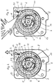
- the clutch shown in the figures has a Clutch disc 2.
- the clutch disc 2 is rotatable about a common axis 18 with a belt reel 1 of a seat belt retractor that is designed as an automatic lifting roller, stored.
- a Such automatic lifting roller is from the DE-C-37 11 537 known.
- With this belt retractor are the coil 1 and the clutch disc 2 rotatable on a bearing leg 15 of a U-shaped Bearing needle 26 stored. This arrangement is again pivotable about one of a bearing leg 17 formed axis of rotation for a rotational movement this axis mounted.
- a pull cable 3 is connected to the clutch disc 2, which the belt tensioner movement does not Belt tensioner shown in detail on the clutch disc 2 transmits.
- the rope 3 is on this appropriately designed winding part of the clutch disc wound up in a known manner.
- the pull rope 3 in the manner on the Clutch disc can be wound, as it from the EP 0 529 265 A1 is known.
- This will be a spiral Cable guide used on the clutch disc. This ensures that the belt tensioner movement 3 in a rotational movement of the clutch disc 2 is converted.
- a driver device which a non-rotatable connection between the clutch disc 2 and can produce the coil 1.
- This takeaway device has on the clutch disc 2 slidable mounted driving elements designed as gripper jaws 4.
- the driving elements 4 are on bearing jaws 7 of the clutch disc 2 slidable stored.
- the driving elements 4 have on the outside directed serrations 19, which with the inside a rotationally connected to the spool 1 drive ring 20 can come into positive engagement.
- This frictional connection can be by positive or frictional engagement getting produced.
- a control part 5 is provided on its circumference distributed controls 6 are provided.
- the driving elements 4 are Control elements 6 at equal angular distances from each other about the common axis 18 or the bearing arm 15 arranged.
- the driving elements 4 are three driving elements 4 and three assigned Control elements 6 are provided in the form of control pins.
- a positioning plate 34 are the driving elements 4 in their normal position e.g. by frictional force between the positioning plate 34 and the clutch disc 2 held.
- the first locking device 10 is formed from one to one Lever 12 provided pin. This pin locks the clutch disc 2 on the frame 8 or on one Coupling housing 9, which shows like FIG. 1, between the front cover 30 and the frame 8 is provided.
- the clutch housing 9 is rigidly connected to the frame 8.
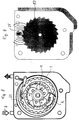
- the lever 12 is around a pivot axis 16 pivotable on the frame 8 or Coupling housing 9 mounted. In this normal position can due to the pivotable guidance of the locking device 10 (locking pin) around the Pivot axis 16, the clutch disc 2 together with the coil 1 pivotal movements between the in Fig. 2nd shown normal position and a blocking position carry out.
- the further movement of the pull rope 3 is transferred from the clutch disc 2 and those located thereon Bearing jaws on the driving elements 4.
- the through the Lock 14 controls held stationary come in the area of the control surfaces 11 (in 3)), as shown in Fig. 5 is.
- the control surfaces 11 are in the further rotation on the stationary controls 6 passed, and in the direction of in Fig. 5th shown arrows moved radially outwards.
- At this movement come in the illustrated embodiment first teeth of teeth 19, which is designed as fangs 21, with a the teeth provided on the inside of the driving ring 20 22 engaged.
- the driving ring 20 can be designed in this way be that it has an internal ring part, which is made of a softer material than the material the driving elements 4. This ensures that the driving elements 4 with their respective Toothings 19 dig into the soft material and so a perfect adhesion produce between the clutch disc 2 and the coil 1.
- the inside is preferably Ring part of a hard, for example made of steel existing outer ring part on the driving ring 20 includes so that a counter bearing for the driving force is formed.
- FIG. 9 shows a flexible ratchet, which by moving in a pretensioner movement Traction rope 3 in an engagement position shown in FIG. 9 with a set of teeth is rotatably connected to the coil 1.
- this is for example the main locking teeth 23 on the coil 1st
- An acoustic signal generator is hereby achieved, which indicates that the belt tensioner has been triggered is.
- the belt tensioner triggered by a vibration or otherwise without an accident-related blocking of the webbing retractor has come the vehicle occupant when actuating, in particular when putting on and taking off the seat belt, by the acoustic signal the triggered state the belt tensioner displayed so that it becomes a Workshop trip is arranged.
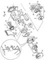
- FIG. 10 shows an exploded perspective view modified coupling parts for one Automatic belt retractors with a fixed winding shaft axis 18 shown.
- the winding shaft axis or common Axle for the clutch disc 2 and the webbing reel 1 is formed by the bearing leg 15 the U-shaped bearing needle.
- This U-shaped bearing needle is however through recesses 36 and 37 in the end Housing caps 30 and 35 on a pivoting movement prevented, so that the bearing leg 15 a fixed axis for the webbing reel 1 and Clutch disc 2 forms.
- controls 33 provided which is stationary on the clutch housing 9 an axially extending sleeve 38 is provided are. These controls 33 come with the control surfaces 11 in engagement with the driving elements 4, if this with the outside in the engaged position the driving ring 20 are brought.
- Webbing-sensitive and vehicle-sensitive sensor device 40 acts on locking pawls supported on the frame 8 41, 42, which with the blocking teeth 23 and 24 can come into engagement with the coil 1. This intervention takes place when Pull rope 3 loose webbing layers - as already explained - are eliminated.
- the pawls are actuated independently from the sensor device.
- the pawl 41, 42 by a resilient holding part 43 in Rest position held. In this rest position is the Pawl out of engagement with the locking teeth or with the locking teeth 23, 24 of the belt reel 1.
- An actuating part is used to actuate the pawl 41, 42 44.
- This actuator 44 is under the bias of a spring 45.
- the spring 45 and the actuating part 44 are shown in FIG Fig. 11 also held in the rest position. this will reached by a holding pin 46.
- the holding pin 46 is designed as a shear pin and can by a Moving component when tightening the seat belt 47 are sheared off.
- the component 47 can to the Clutch disc 2 be formed and acts as a shear element for the holding pin 46.
- the actuating part 44 can via an intermediate lever 48 on the Pawl 41, 42 act.
- the intermediate lever 48 and the holding part 43 is a common retaining ring for positioning 49, for example made of plastic, is provided.
- This retaining ring 49 is inserted into the housing 9. With the help of a mounting pin 50, the retaining ring 49 be attached to the housing 9. Also the holding pin 46 can on the housing 9 for holding the spring 45 and the actuating part 44 in their rest position be fixed.
Landscapes
- Engineering & Computer Science (AREA)
- Mechanical Engineering (AREA)
- Automotive Seat Belt Assembly (AREA)
- Flexible Shafts (AREA)
Claims (26)
- Dispositif de couplage destiné à transmettre le mouvement de retension qui s'exerce sur un câble de tension (3) à un dévidoir de bande de ceinture (1) d'un dispositif d'enroulement de ceinture de sécurité automatique, ayant un disque de couplage (2) qui est connecté au câble de tension (3) et un dispositif d'entraínement (4, 7) qui, dans le cas où un mouvement se produit dans le câble de tension (3), connecte le disque de couplage (2) d'une manière non rotative au dévidoir de bande de ceinture (1), dans lequel un mouvement de rotation du disque de couplage (2) provoqué par le mouvement dans le câble de tension est transmis au dévidoir (1), dans lequel le disque de couplage (2), en fonctionnement normal, est bloqué à l'aide d'un dispositif de blocage (10) afin d'empêcher la rotation sur le cadre (8) du dispositif d'enroulement automatique ou sur un boítier de dispositif de couplage (9) connecté au cadre (8), le dispositif de blocage (10) peut être dégagé du fait de la force exercée par le mouvement du câble de tension, le dispositif d'entraínement (4, 7) comprend des éléments d'entraínement (4) qui, après dégagement du dispositif de blocage (10), se déplacent sous l'effet de la rotation du disque de couplage (2) d'une position normale située vers l'intérieur dans le sens radial à une position extérieure radiale en prise avec le dévidoir de bande de ceinture (1), et dans lequel, dans cette position en prise, le disque de couplage (2) et le dévidoir (1) sont mutuellement connectés d'une manière non rotative pour une rotation commune par rapport à un axe (18), et dans lequel, après dégagement du dispositif de blocage (10), un élément de blocage préliminaire (12) supporté sur le cadre (8) ou le boítier de dispositif de couplage (9) se met en prise avec le dévidoir (1) et bloque le dévidoir (1) pendant le mouvement suivant du câble de tension afin d'empêcher la rotation.
- Dispositif de couplage selon la revendication 1, caractérisé en ce que le mouvement de rotation dans la direction opposée à la direction dans laquelle le câble de tension est tiré, est bloqué.
- Dispositif de couplage selon la revendication 1 ou 2, caractérisé en ce que l'élément de blocage préliminaire (12) prend la forme d'un levier supporté sur le cadre (8) ou le boítier de dispositif de couplage (9).
- Dispositif de couplage selon l'une quelconque des revendications 1 à 3, caractérisé en ce que le dispositif de blocage préliminaire (10) est fixé à l'élément de blocage préliminaire (12).
- Dispositif de couplage selon l'une quelconque des revendications 1 à 4, caractérisé en ce que les éléments d'entraínement (4) sont montés de manière déplaçable sur le disque de couplage (2).
- Dispositif de couplage selon l'une quelconque des revendications 1 à 5, caractérisé en ce que les éléments d'entraínement (4) comprennent des surfaces de commande (11), qui peuvent être guidées le long d'éléments de commande (6, 33) qui sont maintenus fixes par rapport au cadre (8) ou au boítier de dispositif de couplage (9) pendant le mouvement des éléments d'entraínement (4) à la position en prise.
- Dispositif de couplage selon l'une quelconque des revendications 1 à 6, caractérisé en ce que, en fonctionnement normal, le disque de couplage (2) est connecté de manière non rotative aux éléments de commande (6) au moyen d'un deuxième dispositif de blocage (13) et en ce que, après le dégagement du deuxième dispositif de blocage (13), le disque de couplage (2) peut tourner sous l'effet du mouvement du câble de tension par rapport aux éléments de commande (6) toujours maintenus de manière fixe sur le cadre (8) ou le boítier de dispositif de couplage (9).
- Dispositif de couplage selon l'une quelconque des revendications 1 à 7, caractérisé en ce que les éléments de commande (6) sont maintenus de manière fixe sur le cadre (8) ou le boítier de dispositif de couplage (9) au moyen d'un troisième dispositif de blocage (14) jusqu'à ce que la connexion non rotative entre le disque de couplage (2) et le dévidoir (1) soit assurée à l'aide des éléments d'entraínement (4).
- Dispositif de couplage selon la revendication 8, caractérisé en ce que le troisième dispositif de blocage (14) est ensuite dégagé si la connexion non rotative entre le dévidoir (1) et le disque de couplage (2) est produite.
- Dispositif de couplage selon l'une quelconque des revendications 1 à 9, caractérisé en ce que les trois dispositifs de blocage (10, 13, 14) prennent la forme de broches qui sont coupées par cisaillement sous l'effet des forces exercées par le mouvement du câble de tension.
- Dispositif de couplage< selon l'une quelconque des revendications 1 à 8, caractérisé en ce que les éléments de commande (33) sont prévus sur le boítier de dispositif de couplage (9).
- Dispositif de couplage selon l'une quelconque des revendications 1 à 11, caractérisé en ce que les éléments d'entraínement (4) prennent la forme de mâchoires qui peuvent être déplacées sur le disque de couplage (2) et peuvent être mises en prise non rotative avec la périphérie intérieure d'un anneau d'entraínement (2) prévu sur le dévidoir (1).
- Dispositif de couplage selon la revendication 12, caractérisé en ce que les éléments d'entraínement (4) comprennent un agencement de dents (19) qui peut être mis en prise avec la périphérie intérieure de l'anneau d'entraínement (20).
- Dispositif de couplage selon la revendication 12 ou 13, caractérisé en ce qu'une dent qui prend la forme d'une dent d'accrochage (21) dans l'agencement de dents (19) peut être déplacée en prise avec la périphérie intérieure de l'anneau d'entraínement (20) lors du déplacement de l'élément d'entraínement respectif (4).
- Dispositif de couplage selon l'une quelconque des revendications 12 à 14, caractérisé en ce que l'anneau d'entraínement (20) comprend un agencement de dents (22) sur sa périphérie intérieure.
- Dispositif de couplage selon l'une quelconque des revendications 1 à 15, caractérisé en ce que les éléments d'entraínement (4) se composent d'un matériau plus dur que la partie annulaire s'étendant intérieurement de l'anneau d'entraínement (20), avec laquelle les éléments d'entraínement (4) viennent en prise.
- Dispositif de couplage selon la revendication 16, caractérisé en ce que la partie annulaire s'étendant intérieurement de l'anneau d'entraínement (20) est recouverte par une partie annulaire extérieure plus dure.
- Dispositif de couplage selon l'une quelconque des revendications 1 à 17, caractérisé en ce que les éléments d'entraínement (4) sont maintenus en position non opérationnelle à l'aide d'une plaque de positionnement (34).
- Dispositif de couplage selon l'une quelconque des revendications 1 à 18, caractérisé en ce que, sous l'effet du mouvement du câble de tension, un doigt d'encliquetage flexible (25) peut être mis en prise avec un agencement de dents (23) ou (24) qui est connecté de manière non rotative au dévidoir (1).
- Dispositif de couplage selon l'une quelconque des revendications 1 à 19, caractérisé en ce que le disque de couplage (2) et le dispositif d'entraínement (47) peuvent être déplacés d'une seule pièce avec le dévidoir de bande de ceinture (1) sous l'effet d'un mouvement de levage dans une position de blocage, et en ce que, en fonctionnement normal, le dispositif de blocage (10) est monté sur le cadre (8) du dispositif d'enroulement automatique ou sur une boítier de dispositif de couplage (9) connecté au cadre (8).
- Dispositif de couplage selon la revendication 20, caractérisé en ce que l'axe de pivot (16) se situe à proximité d'un axe de rotation (17) par rapport auquel s'effectue le mouvement de levage du dévidoir (1), qui prend la forme d'un mouvement de rotation.
- Dispositif de couplage selon l'une quelconque des revendications 1 à 21, caractérisé en ce qu'un cliquet de blocage (41, 42), destiné à bloquer un dévidoir de ceinture d'un tambour d'enroulement de ceinture de sécurité afin d'empêcher que la ceinture puisse être tirée, peut être activé pour se mettre en prise de blocage avec le dévidoir de ceinture (1) sous l'action d'un composant (47) qui se déplace lorsque la ceinture de sécurité est serrée.
- Dispositif de couplage selon la revendication 22, caractérisé en ce qu'une partie d'actionnement (44) qui déplace le cliquet de blocage (41, 42) en position en prise avec le dévidoir de ceinture (1) peut être retirée d'une position non opérationnelle lorsque la ceinture de sécurité est serrée.
- Dispositif de couplage selon la revendication 23, caractérisé en ce que la partie d'actionnement (44) est prétendue dans la direction d'actionnement.
- Dispositif de couplage selon l'une quelconque des revendications 22 à 24, caractérisé en ce qu'une partie de retenue (46) est prévue, qui retient le cliquet de blocage (41, 42) dans une position désactivée avec une tension préalable qui est surmontée sous l'effet de la partie d'actionnement (44).
- Dispositif de couplage selon l'une quelconque des revendications 22 à 25, caractérisé en ce que le cliquet de blocage (41, 42) vient à sa position de blocage final sous l'effet de l'inversion d'un mouvement provoqué par l'entraínement tensionneur.
Applications Claiming Priority (2)
| Application Number | Priority Date | Filing Date | Title |
|---|---|---|---|
| DE4327134 | 1993-08-12 | ||
| DE4327134A DE4327134A1 (de) | 1993-08-12 | 1993-08-12 | Kupplung zum Übertragen der auf ein Zugseil wirkenden Rückstrafferbewegung auf eine Gurtbandspule eines Sicherheitsgurtaufrollautomaten |
Publications (2)
| Publication Number | Publication Date |
|---|---|
| EP0638468A1 EP0638468A1 (fr) | 1995-02-15 |
| EP0638468B1 true EP0638468B1 (fr) | 1998-04-22 |
Family
ID=6495053
Family Applications (1)
| Application Number | Title | Priority Date | Filing Date |
|---|---|---|---|
| EP94112518A Expired - Lifetime EP0638468B1 (fr) | 1993-08-12 | 1994-08-10 | Accouplement pour transmettre le mouvement du câble de traction d'un tendeur à la bobine d'un enrouleur de ceinture de sécurité |
Country Status (4)
| Country | Link |
|---|---|
| EP (1) | EP0638468B1 (fr) |
| AT (1) | ATE165290T1 (fr) |
| DE (2) | DE4327134A1 (fr) |
| ES (1) | ES2115823T3 (fr) |
Families Citing this family (5)
| Publication number | Priority date | Publication date | Assignee | Title |
|---|---|---|---|---|
| DE19503150A1 (de) * | 1995-02-01 | 1996-08-08 | Takata Europ Gmbh | Einen Gurtstraffer aufweisende Sicherheitsgurtanordnung in Kraftfahrzeugen |
| DE19609524C2 (de) * | 1996-03-11 | 2000-06-08 | Autoliv Dev | Gurtaufroller-Gurtstrammer-Kombination mit Kraftbegrenzer |
| DE19621772C1 (de) * | 1996-05-30 | 1997-04-10 | Hs Tech & Design | Gurtstraffer für einen Sicherheitsgurt |
| GB2397492B (en) * | 2003-01-24 | 2005-10-12 | Kraft Foods R & D Inc | Cartridge for the preparation of beverages |
| CN113552404A (zh) * | 2021-07-20 | 2021-10-26 | 中国神华能源股份有限公司哈尔乌素露天煤矿 | 一种电缆卷放车保护监控方法、系统及存储介质 |
Family Cites Families (6)
| Publication number | Priority date | Publication date | Assignee | Title |
|---|---|---|---|---|
| DE8600002U1 (de) * | 1986-01-02 | 1989-05-03 | Trw Repa Gmbh, 73553 Alfdorf | Rotations-Gurtstraffer für Sicherheitsgurte |
| DE3715846A1 (de) * | 1987-05-12 | 1988-12-01 | Trw Repa Gmbh | Sicherheitsgurtaufroller mit rueckstrammvorrichtung |
| DE3872157D1 (de) * | 1987-10-23 | 1992-07-23 | Autoliv Kolb Gmbh & Co | Sicherheitsgurt-strammvorrichtung. |
| DE3810701A1 (de) * | 1988-03-29 | 1989-10-12 | Trw Repa Gmbh | Rueckstrammvorrichtung |
| JPH01158260U (fr) * | 1988-04-19 | 1989-11-01 | ||
| DE69316855T2 (de) * | 1992-12-02 | 1998-07-23 | Alliedsignal Ltd | Sicherheitsgurtaufroller mit Gurtstrammer |
-
1993
- 1993-08-12 DE DE4327134A patent/DE4327134A1/de not_active Withdrawn
-
1994
- 1994-08-10 AT AT94112518T patent/ATE165290T1/de active
- 1994-08-10 EP EP94112518A patent/EP0638468B1/fr not_active Expired - Lifetime
- 1994-08-10 ES ES94112518T patent/ES2115823T3/es not_active Expired - Lifetime
- 1994-08-10 DE DE59405763T patent/DE59405763D1/de not_active Expired - Fee Related
Also Published As
| Publication number | Publication date |
|---|---|
| DE4327134A1 (de) | 1995-02-16 |
| ATE165290T1 (de) | 1998-05-15 |
| EP0638468A1 (fr) | 1995-02-15 |
| DE59405763D1 (de) | 1998-05-28 |
| ES2115823T3 (es) | 1998-07-01 |
Similar Documents
| Publication | Publication Date | Title |
|---|---|---|
| DE60129755T2 (de) | Sicherheitsgurt-Retraktor | |
| DE3876081T2 (de) | Sicherheitsgurt mit spannvorrichtung. | |
| DE60122999T2 (de) | Gurtaufroller | |
| DE10213906A1 (de) | Leistungsstraffer | |
| DE10039364C2 (de) | Vorrichtung zum Aufrollen eines Sicherheitsgurtes | |
| DE4227781C2 (de) | Gurtaufroller mit an der Gurtspule angreifendem Gurtstraffer | |
| DE10013869C2 (de) | Komfort-Aufwickeleinrichtung für einen Sicherheitsgurt mit Motorrückholung | |
| DE102018116126B4 (de) | Gurtaufroller für eine Sicherheitsgurteinrichtung eines Kraftfahrzeuges | |
| EP2944520B1 (fr) | Enrouleur de ceinture pour une ceinture de sécurité de véhicule | |
| DE102020208905A1 (de) | Gurtaufroller | |
| DE2418300A1 (de) | Trommel zur aufnahme eines bandgurtes | |
| EP1656286B1 (fr) | Enrouleur de ceinture | |
| DE69605335T2 (de) | Gurtaufroller mit Getriebemechanismus | |
| EP0638468B1 (fr) | Accouplement pour transmettre le mouvement du câble de traction d'un tendeur à la bobine d'un enrouleur de ceinture de sécurité | |
| DE10085153B4 (de) | Sicherheitsgurtvorrichtung mit Sicherheitsgurtretraktor mit Verriegelungsvorrichtung | |
| DE29506208U1 (de) | Kupplung zur Drehmomentübertragung von einem durch ein Treibmittel betriebenen Antrieb auf eine Gurtwelle eines Sicherheitsgurtaufrollers zum Strammen eines Sicherheitsgurtes | |
| DE10101048A1 (de) | Sicherheitsgurtvorrichtung | |
| DE19727083C2 (de) | Sitzgurtaufroller mit Energieabsorption | |
| DE9217304U1 (de) | Sitzgurt-Vorspanner vom Drehwellen-Rückzieh-Typ | |
| DE69106973T2 (de) | Sicherheitsgurtstrammer. | |
| DE102019203356B4 (de) | Reversibler Gurtstraffer für einen Sicherheitsgurt | |
| DE102006036554B4 (de) | Gurtaufroller für ein Sicherheitsgurtsystem | |
| DE19544918A1 (de) | Sicherheitsgurtaufroller | |
| DE2616906A1 (de) | Selbstarretierende sicherheitsgurt- aufspulvorrichtung | |
| WO2024061787A1 (fr) | Enrouleur de ceinture pour un dispositif de ceinture de sécurité d'un véhicule automobile |
Legal Events
| Date | Code | Title | Description |
|---|---|---|---|
| PUAI | Public reference made under article 153(3) epc to a published international application that has entered the european phase |
Free format text: ORIGINAL CODE: 0009012 |
|
| AK | Designated contracting states |
Kind code of ref document: A1 Designated state(s): AT DE ES FR GB IT NL SE |
|
| 17P | Request for examination filed |
Effective date: 19950627 |
|
| 17Q | First examination report despatched |
Effective date: 19960812 |
|
| GRAG | Despatch of communication of intention to grant |
Free format text: ORIGINAL CODE: EPIDOS AGRA |
|
| GRAG | Despatch of communication of intention to grant |
Free format text: ORIGINAL CODE: EPIDOS AGRA |
|
| GRAH | Despatch of communication of intention to grant a patent |
Free format text: ORIGINAL CODE: EPIDOS IGRA |
|
| GRAH | Despatch of communication of intention to grant a patent |
Free format text: ORIGINAL CODE: EPIDOS IGRA |
|
| GRAA | (expected) grant |
Free format text: ORIGINAL CODE: 0009210 |
|
| AK | Designated contracting states |
Kind code of ref document: B1 Designated state(s): AT DE ES FR GB IT NL SE |
|
| PG25 | Lapsed in a contracting state [announced via postgrant information from national office to epo] |
Ref country code: NL Free format text: LAPSE BECAUSE OF FAILURE TO SUBMIT A TRANSLATION OF THE DESCRIPTION OR TO PAY THE FEE WITHIN THE PRESCRIBED TIME-LIMIT Effective date: 19980422 |
|
| REF | Corresponds to: |
Ref document number: 165290 Country of ref document: AT Date of ref document: 19980515 Kind code of ref document: T |
|
| GBT | Gb: translation of ep patent filed (gb section 77(6)(a)/1977) |
Effective date: 19980423 |
|
| REF | Corresponds to: |
Ref document number: 59405763 Country of ref document: DE Date of ref document: 19980528 |
|
| ITF | It: translation for a ep patent filed | ||
| RAP2 | Party data changed (patent owner data changed or rights of a patent transferred) |
Owner name: BREED AUTOMOTIVE TECHNOLOGY, INC. |
|
| ET | Fr: translation filed | ||
| REG | Reference to a national code |
Ref country code: ES Ref legal event code: FG2A Ref document number: 2115823 Country of ref document: ES Kind code of ref document: T3 |
|
| PG25 | Lapsed in a contracting state [announced via postgrant information from national office to epo] |
Ref country code: SE Free format text: LAPSE BECAUSE OF FAILURE TO SUBMIT A TRANSLATION OF THE DESCRIPTION OR TO PAY THE FEE WITHIN THE PRESCRIBED TIME-LIMIT Effective date: 19980722 |
|
| NLT2 | Nl: modifications (of names), taken from the european patent patent bulletin |
Owner name: BREED AUTOMOTIVE TECHNOLOGY, INC. |
|
| PG25 | Lapsed in a contracting state [announced via postgrant information from national office to epo] |
Ref country code: AT Free format text: LAPSE BECAUSE OF NON-PAYMENT OF DUE FEES Effective date: 19980810 |
|
| NLV1 | Nl: lapsed or annulled due to failure to fulfill the requirements of art. 29p and 29m of the patents act | ||
| PLBE | No opposition filed within time limit |
Free format text: ORIGINAL CODE: 0009261 |
|
| STAA | Information on the status of an ep patent application or granted ep patent |
Free format text: STATUS: NO OPPOSITION FILED WITHIN TIME LIMIT |
|
| 26N | No opposition filed | ||
| PGFP | Annual fee paid to national office [announced via postgrant information from national office to epo] |
Ref country code: FR Payment date: 20000803 Year of fee payment: 7 |
|
| PGFP | Annual fee paid to national office [announced via postgrant information from national office to epo] |
Ref country code: ES Payment date: 20000816 Year of fee payment: 7 |
|
| PG25 | Lapsed in a contracting state [announced via postgrant information from national office to epo] |
Ref country code: ES Free format text: LAPSE BECAUSE OF NON-PAYMENT OF DUE FEES Effective date: 20010811 |
|
| REG | Reference to a national code |
Ref country code: GB Ref legal event code: IF02 |
|
| PG25 | Lapsed in a contracting state [announced via postgrant information from national office to epo] |
Ref country code: FR Free format text: LAPSE BECAUSE OF NON-PAYMENT OF DUE FEES Effective date: 20020430 |
|
| REG | Reference to a national code |
Ref country code: FR Ref legal event code: ST |
|
| PGFP | Annual fee paid to national office [announced via postgrant information from national office to epo] |
Ref country code: GB Payment date: 20020626 Year of fee payment: 9 |
|
| PGFP | Annual fee paid to national office [announced via postgrant information from national office to epo] |
Ref country code: DE Payment date: 20020830 Year of fee payment: 9 |
|
| REG | Reference to a national code |
Ref country code: GB Ref legal event code: 732E |
|
| PG25 | Lapsed in a contracting state [announced via postgrant information from national office to epo] |
Ref country code: GB Free format text: LAPSE BECAUSE OF NON-PAYMENT OF DUE FEES Effective date: 20030810 |
|
| PG25 | Lapsed in a contracting state [announced via postgrant information from national office to epo] |
Ref country code: DE Free format text: LAPSE BECAUSE OF NON-PAYMENT OF DUE FEES Effective date: 20040302 |
|
| GBPC | Gb: european patent ceased through non-payment of renewal fee |
Effective date: 20030810 |
|
| REG | Reference to a national code |
Ref country code: ES Ref legal event code: FD2A Effective date: 20020911 |
|
| PG25 | Lapsed in a contracting state [announced via postgrant information from national office to epo] |
Ref country code: IT Free format text: LAPSE BECAUSE OF NON-PAYMENT OF DUE FEES;WARNING: LAPSES OF ITALIAN PATENTS WITH EFFECTIVE DATE BEFORE 2007 MAY HAVE OCCURRED AT ANY TIME BEFORE 2007. THE CORRECT EFFECTIVE DATE MAY BE DIFFERENT FROM THE ONE RECORDED. Effective date: 20050810 |