EP0638496B1 - Vorrichtung und Verfahren zum Einführen von blattformigem Material in eine Maschine - Google Patents
Vorrichtung und Verfahren zum Einführen von blattformigem Material in eine Maschine Download PDFInfo
- Publication number
- EP0638496B1 EP0638496B1 EP94111608A EP94111608A EP0638496B1 EP 0638496 B1 EP0638496 B1 EP 0638496B1 EP 94111608 A EP94111608 A EP 94111608A EP 94111608 A EP94111608 A EP 94111608A EP 0638496 B1 EP0638496 B1 EP 0638496B1
- Authority
- EP
- European Patent Office
- Prior art keywords
- plate
- organs
- motion
- matters
- fact
- Prior art date
- Legal status (The legal status is an assumption and is not a legal conclusion. Google has not performed a legal analysis and makes no representation as to the accuracy of the status listed.)
- Expired - Lifetime
Links
- 238000000034 method Methods 0.000 title claims abstract description 10
- 239000000463 material Substances 0.000 title description 7
- 210000000056 organ Anatomy 0.000 claims description 25
- 244000208734 Pisonia aculeata Species 0.000 claims 2
- 230000009466 transformation Effects 0.000 description 7
- 230000000694 effects Effects 0.000 description 6
- 238000003780 insertion Methods 0.000 description 6
- 230000037431 insertion Effects 0.000 description 6
- 238000006073 displacement reaction Methods 0.000 description 2
- 238000010276 construction Methods 0.000 description 1
- 230000000717 retained effect Effects 0.000 description 1
- 238000005096 rolling process Methods 0.000 description 1
Images




Classifications
-
- B—PERFORMING OPERATIONS; TRANSPORTING
- B65—CONVEYING; PACKING; STORING; HANDLING THIN OR FILAMENTARY MATERIAL
- B65H—HANDLING THIN OR FILAMENTARY MATERIAL, e.g. SHEETS, WEBS, CABLES
- B65H3/00—Separating articles from piles
- B65H3/02—Separating articles from piles using friction forces between articles and separator
- B65H3/06—Rollers or like rotary separators
-
- B—PERFORMING OPERATIONS; TRANSPORTING
- B65—CONVEYING; PACKING; STORING; HANDLING THIN OR FILAMENTARY MATERIAL
- B65H—HANDLING THIN OR FILAMENTARY MATERIAL, e.g. SHEETS, WEBS, CABLES
- B65H3/00—Separating articles from piles
- B65H3/08—Separating articles from piles using pneumatic force
- B65H3/12—Suction bands, belts, or tables moving relatively to the pile
- B65H3/124—Suction bands or belts
- B65H3/126—Suction bands or belts separating from the bottom of pile
Definitions
- the subject of the present invention is a method for introducing a material into a plate into a machine for converting this material into a plate, in particular corrugated cardboard plates, and a device for carrying out the method.
- the device comprises a magazine intended to receive a stack of sheets.
- a gauge is placed at the front of this magazine so that only the bottom sheet of the stack of sheets can pass between the bottom of this gauge and the plane defined by the leaf drive arranged under the magazine .
- the sheet driving device comprises a first series of driving rollers driven by a modulated rotary movement passing from a stop at a speed substantially equal to that of a second series of rollers rotating at constant speed which preferably corresponds to the linear speed of the cardboard plates in the working machine.
- the first series of driving rollers is associated with leaf lifting members, controlled according to the arrival of the front edge of the sheet extracted from the magazine on the first second series roll.
- a first lifting member will be applied against the underside of the sheet being introduced and will raise the entire stack, so that contact is no longer established between the drive members and the sheet being introduced.
- a second lifting member will act, in the same way as the first, on the sheet being introduced.
- the front edge of the sheet being introduced will then reach the third roller of the second series and a third lifting member will be actuated.
- a fourth lifting member will be actuated.
- the object of the present invention is to eliminate the aforementioned drawbacks and, for this purpose, the method for introducing a material into a plate, in particular corrugated cardboard plates, into a machine for converting this material into a plate using a first lower transport member and acting on the lower plate of a stack of plates, animated in a sequential movement, associated with mobile support members of the stack of plates remaining in a magazine, of a second transport member arranged following the first transport member, animated by a uniform movement, said transport members being arranged in a suction box, is characterized in that the movement of the mobile support members is controlled as a function of the displacement of the rear edge of the lower plate of said stack of plates being introduced, so that the mobile support members (8) support the stack of plates (2) remaining in the store (13) as the said lower plate (4a) moves.
- the device for implementing the method according to claim 1, comprises a suction box in which are arranged first plate transport members animated in a sequential movement, said suction box being placed below a stack of plates contained in a magazine having a front wall adjustable vertically with respect to the upper plane of the first transport members to allow the passage of the lower plate of the stack of plates, of the second transport members of the plates animated with a uniform movement and arranged at following the first transport members, and mobile members for supporting the stack of plates, and is characterized in that the mobile members for supporting the stack of plates comprise a set of rollers mounted on rods controlled by transverse shafts oscillating, said set of rollers being disposed on either side of the first plate transport members, in that each oscillating transverse shaft is provided, at one of its ends, with a lever controlled by a piloting member driven in phase with the displacement of the rear edge of the plate during insertion, said lever being equipped with return means for applying it in the direction of the control member, in that each oscillating transverse shaft is equipped, at one of its ends, of
- control member is constituted by an endless belt comprising a control shoe acting, during the movement of the endless belt against the end of each of the levers of the transverse shafts, said levers being provided return means constituted by springs.
- the steering member is constituted by cams acting on each of the levers of the transverse shafts.
- the locking means comprise at least one clutch locked in rotation, during the upward movement cycle of the mobile support members and released, during the downward movement cycle of the mobile support members, these ci then simultaneously moving down.
- the advantage obtained thanks to this invention lies essentially in the fact that the introduction of plates in a machine working them can be carried out without friction occurring between the upper face of the support member of the stack of plates when moving a plate during insertion.
- another advantage lies in the fact that the weight of the stack of plates remaining in the magazine is retained as the plate being introduced advances in the device, which greatly improves the precision of the introduction of the plates by considerably reducing the frictional forces between the plate being introduced and the stack remaining in the magazine.
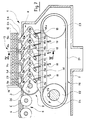
- the introduction device 1 of FIG. 1 comprises a first conveyor 2 driven by a sequential movement authorizing the modulation of the linear speed of its endless belts 3 of a zero speed at a speed corresponding to the linear speed of the plates 4 in the processing machine (not shown).
- This first conveyor 2 is followed by a second conveyor 5 represented here by transverse rollers 6 and driven continuously at a speed corresponding to the linear speed of the plates 4 in the transformation machine.
- These two transporters 2 and 5 are here placed inside a suction box 7.
- the first conveyor 2 is associated with a support member 8 constituted by rods 9 mounted by one of their ends, on transverse shafts 10. Their other end is equipped of rollers 11.
- a stack of plates 12 is placed in a magazine 13 located above the first conveyor 2.
- This magazine 13 comprises inter alia a front wall 14 adjustable vertically to allow the passage of the plates 4 between its lower part and the plane upper defined by endless belts 3.
- the arrangement of the various members, shown in FIG. 1, corresponds to the location they occupy at the end of the plate 4 insertion cycle, that is to say that all the rollers 11 occupy a higher position and , therefore, isolate the lower plate 4a of the conveyor 2 thereby supporting the stack of plates 12.
- the endless belts 3 are in the slowing phase.
- suction box 7 has not been drawn in FIGS. 2 to 6.
- the endless belts 3 of the first conveyor 2 will be set in motion, from zero speed to machine speed and therefore will drive the plate 4a, under the front wall 14 of the magazine 13.
- a control member 16 (see Fig. 7 and 8) will have acted so as to pivot up the first link 9a of the support member 8 so that the roller 11a support the stack of plates 12 remaining in the magazine 13.
- the control member 16 is driven in synchronism with the advance of the plate 4a on the endless belts 3, which means that, as soon as the rear edge 4b of the plate 4a will have left the level of the roller 11a, this will be brought into contact with the lower plate 4c of the stack of plates 12 and will support the latter without there having been friction between the roller 11a and the plate 4a.
- the rod 9a remains in the high position.
- FIG. 6 represents the situation while the rear edge 4b of the plate 4a leaves the zone of action of the roller 11d, this just before the roller 11e is also raised after the rear edge 4b of the plate 4a has left its area of action and that we find our in the situation represented by FIG. 1 and that the endless belts 3 of the first conveyor 2 are again stopped.
- the introductory cycle can then start again.
- FIG. 7 represents, in diagrammatic view and in partial section, a first embodiment of an introduction device 1 comprising a first transport member having the form of a first conveyor 2 with endless belts arranged one next to each other across the width of the insertion device 1.
- a magazine 13 intended to receive a stack of plates 12 is located immediately above the first conveyor 2.
- a second transport member 5, formed here by rollers 6, follows first conveyor 2.
- the situation shown in this figure corresponds to that shown in figure 1.
- the first conveyor 2 is driven by a sequential movement passing from zero speed to a speed corresponding to the linear speed of movement of the plates 4 in the transformation machine (not shown), and the second conveyor 5 is, in turn, driven at the same speed as the transformation machine.
- the lower plate of the stack of plates 12 is supported by the rollers 11a to 11e of the support member 8.
- the endless belts 3 of the first conveyor 2 are driven by a transverse shaft 17.
- these endless belts 3 are toothed belts, coated with a material having a good adhesion characteristic for driving the plate 4a of the stack 12 with good precision, also conferred by the choice of toothed belts.
- the rollers 11a to 11e are each mounted at one end of the links 9a to 9e, the other end of which is keyed or pinned to the oscillating transverse shafts 10a to 10e.
- Levers 18a to 18e are also mounted at one end of the oscillating transverse shafts 10a to 10e while the links 9a to 9e are placed between the lateral space existing between the endless belts 3 of each of the first conveyors 2, this across the width of the insertion device 1.
- Each of the levers 18a to 18e is also keyed or pinned to the end of the oscillating transverse shafts 10a to 10e and is provided with actuating rollers 19a to 19e intended to be controlled by a control member 16.
- the levers 18a to 18e are each fitted with return springs 15 intended to apply them in the direction of the control member. piloting 16.
- This piloting member 16 comprises, for each series of support members 8, an endless belt 21 passing around a drive pulley 22 and a driven pulley 23, the drive pulley 22 being keyed to a rotary transverse shaft 24 rotating in phase with the first conveyor 2, so that the movement of the support member 8 is controlled by the movement of the rear edge 4b of the plate to be introduced into the processing machine.
- the endless belt 21 of the control member 16 is advantageously a toothed belt on which is fixed a control shoe 25 intended to act, during its passage, on each of the actuating rollers 19a to 19th; the endless belt 21 of the control member 16 can also be supported, in its upper strand, by a sole 30 or by notched rollers. As shown in FIG.
- the two conveyors 2 and 5 are arranged inside the suction box 7, the upper face 26 of which is provided with longitudinal and transverse openings (not shown) to allow the passage of the endless belts 3, rollers 6 of the conveyor 5 and rollers 11a to 11e of the support members 8 distributed between the endless belts 3 across the width of the insertion device 1.
- the conveyor 5 can also be placed after the box suction 7 and can take, for example, the form of a simple plate driving device consisting of rollers or transport clamps of the same type as that encountered in printing or cardboard converting machines.
- Each of the endless belts 3 can be supported in its active part under the stack of plates 12 using a support sole 29 or notched rollers (not shown).
- a unidirectional device 31 shown in FIG. 9 is mounted at the end of each of the oscillating transverse shafts 10a to 10e so that the vertical position of the rollers 11a to 11e is temporarily maintained after the passage of the control shoe 25.
- FIG. 8 represents a second embodiment of the device of FIG. 7 in which the support member 8 comprises a piloting member 16 produced by cams 27a to 27e, mounted on rotary transverse shafts 28a to 28e, intended for act on the actuating rollers 19a to 19e of the levers 18a to 18e in the same way as the control shoe 25 of the embodiment shown in FIG. 7. All the other elements of this FIG. 8 have the same reference signs as those of Figure 7 because they are identical.
- the rotation of the transverse shafts 28a to 28e supporting the cams 27a to 27e is carried out using a conventional gear train (not shown), so that the movement transmitted to the support member 8 is in phase with the movement of the rear edge 4b of the plate 4a during introduction into the transformation machine.
- FIG. 9 represents a sectional view along IX-IX of FIG. 7 in which the arrangement of the various members is seen in the width of the introduction device 1.
- the stack of plates 12 also rests on the rollers 11a in 11e and in this view, only the roller 11b of the series is shown for each of the support members 8.
- One of the ends of the oscillating transverse shaft 10b, as well as that of each of the transverse shafts oscillating 10a, 10c, 10d and 10e, is equipped with a unidirectional device constituted in this example by a free wheel 31 engaged with a series of pinions 32 of a gear train 34 (see Fig. 10) and with the pinion 33 of a locking device 35 constituted by an electromagnetic clutch 36.
- Each oscillating transverse shaft 10a to 10b is held in bearings 37 and 38 arranged in the side walls of the suction box 7, and the return pulleys 39 of the endless belts 3 are mounted on rolling bearings 40 arranged along the transverse shaft 10b while the other transverse shafts 10a, 10c, 10d and 10e do not support any pulley.
- the links 9b are pinned to the oscillating transverse shaft 10b and, therefore, its oscillating movement will be transmitted to the links supporting the rollers 11b.
- This oscillating movement, coming from the steering member 16 will, of course, also be transmitted at the desired time to the other oscillating transverse shafts 10a, 10c, 10d and 10e.
- the electromagnetic clutch 36 will be anchored, by its fixed part, against one of the frames 41 of the introduction device 1.
- the endless toothed belt 21 of the control member 16 is preferably driven by a motor 42 but one could easily imagine driving it via a gearbox coupled to the drive control of the first conveyor 2 at modulated speed so that the two drives are in phase with one 'other.
- the function of the locking member 34 therefore makes it possible, by means of the freewheel 31, to keep the position of the levers 18a to 18th once they have been pivoted by the action of the control shoe 25 or cams 27a to 27e, the electromagnetic clutch 36 being blocked and preventing any rotation of the pinion 33, and this until the whole plate 4a has been introduced into the transformation machine. Then, the zero speed passage control of the first conveyor will be used to actuate the electromagnetic clutch 36 which will trigger and, under the effect of the return springs 15 (see Fig. 7 and 8), all the levers 18a at 18th will be brought back to their initial position so that the rollers 11a to 11e of the support member 8 are brought into the position shown in FIG. 2.
- FIG. 10 schematically represents an embodiment of the connection of the oscillating transverse shafts 10a to 10e with the locking device 34.
- the freewheels 31 are mounted inside the toothed wheels 43 engaged with the pinions 32 and 33.
- all the oscillating transverse shafts 10a to 10e can be moved angularly and independently of one another in one direction during the cycle of rise of the support members 8 when the clutch 36 is blocked, this by the effect of the free wheels 31, and all the shafts 10a to 10e can be moved angularly and simultaneously during the descent cycle of the support members 8 when the clutch 36 is released.
Landscapes
- Mechanical Engineering (AREA)
- Engineering & Computer Science (AREA)
- Sheets, Magazines, And Separation Thereof (AREA)
- Processing And Handling Of Plastics And Other Materials For Molding In General (AREA)
- Details Of Cutting Devices (AREA)
- Separation, Sorting, Adjustment, Or Bending Of Sheets To Be Conveyed (AREA)
- Making Paper Articles (AREA)
- Machines For Manufacturing Corrugated Board In Mechanical Paper-Making Processes (AREA)
- Attitude Control For Articles On Conveyors (AREA)
- Delivering By Means Of Belts And Rollers (AREA)
- Discharge By Other Means (AREA)
- Forming Counted Batches (AREA)
- Pile Receivers (AREA)
- Feeding Of Articles By Means Other Than Belts Or Rollers (AREA)
- Superconductors And Manufacturing Methods Therefor (AREA)
- Push-Button Switches (AREA)
- Manufacturing Of Printed Wiring (AREA)
- Mechanical Treatment Of Semiconductor (AREA)
Claims (7)
- Verfahren zum Einführen eines plattenförmigen Werkstoffs, vor allem Wellpappebogen, in eine plattenförmige Werkstoffe verarbeitende Maschine mit Hilfe eines ersten unteren Transportorgans (2), das auf die unterste Platte (4a) eines Plattenstapels (12) einwirkt, wobei das besagte Organ mit einer schrittweisen Bewegung angetrieben wird und mit beweglichen Organen (8) zum Abstützen des in einem Magazin (13) verbleibenden Plattenstapels (12) verbunden ist, und eines zweiten mit einer gleichmässigen Bewegung angetriebenen Transportorgans (5) im Anschluss an das erste Transportorgan (2), wobei die besagten Transportorgane (2, 5) in einem Ansaugkasten (7) angeordnet sind, dadurch gekennzeichnet, dass die Bewegung der beweglichen Abstützorgane (8) entsprechend der Bewegung des hinteren Randes (4b) der untersten Platte (4a) des besagten Plattenstapels (12) im Verlaufe des Einführvorgangs gesteuert wird, in der Weise, dass die beweglichen Abstützorgane (8) den im Magazin (13) verbleibenden Plattenstapel (12) entsprechend der Bewegung der besagten untersten Platte (4a) tragen.
- Vorrichtung zur Realisierung des Verfahrens gemäss Patentanspruch 1 mit einem Ansaugkasten (7), in welchem erste eine schrittweise Bewegung ausführende Organe (2) zum Transport der Platten (4, 4a), wobei der besagte Ansaugkasten (7) unter einem Plattenstapel (12) in einem Magazin (13) angeordnet ist, welch letzteres eine Vorderwand (14) umfasst, die in bezug auf die obere Ebene der ersten Transportorgane (2) zur Ermöglichung des Durchgangs der untersten Platte (4a) des Plattenstapels (12) vertikal regulierbar ist, zweite Organe (5) zum Transport der Platten (4a) mit gleichmässiger Bewegung im Anschluss an die ersten Transportorgane (2), sowie bewegliche Organe (8) zum Abstützen des Plattenstapels (12) angeordnet sind, dadurch gekennzeichnet, dass die beweglichen Organe (8) zum Abstützen des Plattenstapels (12) Rollen (11a bis 11e) an Pleuelstangen (9a bis 9e) mit Antrieb durch schwingende Querwellen (10a bis 10e) umfassen, wobei die Rollen (11a bis 11e) auf beiden Seiten der ersten Organe (2) zum Transport der Platten (4a) angeordnet sind, dass jede schwingende Querwelle (10a bis 10e) an einem Ende mit je einem Hebel (18a bis 18e) versehen ist, der durch ein Steuerorgan (16) betätigt wird, das zeitgleich mit der Bewegung des hinteren Randes (4b) der untersten Platte (4a) im Verlaufe des Einführvorgangs angetrieben wird, wobei die besagten Hebel (18a bis 18e) Rückzugmittel (15) umfassen, die dieselben in Richtung der Steuerorgane (16) andrücken, dass jede schwingende Querwelle (10a bis 10e) an einem Ende eine Verriegelungsvorrchtung (34) zum zeitweiligen Beibehalten der Stellung eines der Hebel (18a bis 18e) nach der Aufwärtsbewegung durch das Steuerorgan (16) besitzt, sowie dass die Verriegelungsvorrichtung (34) der einzelnen schwingenden Querwellen (10a bis 10e) zeitgleich mit der Bewegung des ersten Transportorgans (2) betätigt wird.
- Vorrichtung gemäss Patentanspruch 2, dadurch gekennzeichnet, dass das Steuerorgan (16), welches zeitgleich mit der Bewegung des hinteren Randes (4b) der untersten Platte im Verlaufe des Einführvorgangs angetrieben wird, aus einem Endlosriemen (21) mit einem Mitnehmer (25) besteht, der bei der Bewegung des Endlosriemens (21) auf das Ende der einzelnen Hebel (18a bis 18b) der schwingenden Querwellen (10a bis 10b) einwirkt, wobei die besagten Hebel (18a bis 18b) mit aus Federn (15) bestehenden Rückzugmitteln versehen sind.
- Vorrichtung gemäss Patentanspruch 2, dadurch gekennzeichnet, dass das Steuerorgan (16) aus Nocken (27a bis 27e) besteht, die nacheinander auf die Hebel (18a bis 18e) der schwingenden Querwellen (10a bis 10e) einwirken.
- Vorrichtung gemäss Patentanspruch 2, dadurch gekennzeichnet, dass die Verriegelungsmittel (34) wenigstens eine Kupplung (36) umfassen, welche bei der Drehbewegung im Verlaufe der Aufwärtsbewegung der beweglichen Abstützorgane (8) eingekuppelt und bei der Abwärtsbewegung der beweglichen Abstützorgane (8) ausgekuppelt wird, wobei die letzteren sich gleichzeitig nach unten bewegen.
- Vorrichtung gemäss Patentanspruch 5, dadurch gekennzeichnet, dass die Bewegung der beweglichen Abstützorgane (8) nach unten erfolgt, wenn die ersten Organe (2) für den Transport der Platten (4a) mit schrittweiser Bewegung sozusagen eine Nullgeschwindigkeit aufweisen.
- Vorrichtung gemäss Patentanspruch 5, dadurch gekennzeichnet, dass die Verriegelungsvorrichtung (34) eine in einer Richtung wirkende Vorrichtung (31) umfasst, die aus einem an jeder schwingenden Querwelle (10a bis 10e) befestigten Freilaufrad besteht welches an ein Getriebe (31, 32, 33) zum Antrieb der einzelnen schwingenden Querwellen (10a bis 10e) angeschlossen ist.
Applications Claiming Priority (2)
| Application Number | Priority Date | Filing Date | Title |
|---|---|---|---|
| FR9309840 | 1993-08-05 | ||
| FR9309840A FR2708579B1 (fr) | 1993-08-05 | 1993-08-05 | Procédé pour introduire une matière en plaque dans une machine de transformation de cette matière en plaque et dispositif pour la mise en Óoeuvre de ce procédé. |
Publications (2)
| Publication Number | Publication Date |
|---|---|
| EP0638496A1 EP0638496A1 (de) | 1995-02-15 |
| EP0638496B1 true EP0638496B1 (de) | 1997-05-02 |
Family
ID=9450100
Family Applications (1)
| Application Number | Title | Priority Date | Filing Date |
|---|---|---|---|
| EP94111608A Expired - Lifetime EP0638496B1 (de) | 1993-08-05 | 1994-07-26 | Vorrichtung und Verfahren zum Einführen von blattformigem Material in eine Maschine |
Country Status (11)
| Country | Link |
|---|---|
| US (1) | US5464202A (de) |
| EP (1) | EP0638496B1 (de) |
| JP (1) | JP2617687B2 (de) |
| KR (1) | KR0161701B1 (de) |
| AT (1) | ATE152424T1 (de) |
| BR (1) | BR9403167A (de) |
| CA (1) | CA2128138C (de) |
| DE (1) | DE69402927T2 (de) |
| DK (1) | DK0638496T3 (de) |
| ES (1) | ES2102740T3 (de) |
| FR (1) | FR2708579B1 (de) |
Families Citing this family (17)
| Publication number | Priority date | Publication date | Assignee | Title |
|---|---|---|---|---|
| US5651313A (en) * | 1994-09-23 | 1997-07-29 | Ward Holding Company, Inc. | Paperboard processing machine with vacuum transfer system |
| JP4000429B2 (ja) * | 1997-12-25 | 2007-10-31 | 株式会社タナベインターナショナル | ブランクシートの供給装置 |
| US5988625A (en) * | 1998-03-09 | 1999-11-23 | Hub Folding Box Company, Inc. | Upright feeder for packaging manufacturing systems |
| JP2005298078A (ja) * | 2004-04-06 | 2005-10-27 | Sanwa Seisaku Kk | 紙葉給送方法及び装置 |
| SE525914C2 (sv) * | 2004-04-29 | 2005-05-24 | Emba Machinery Ab | Förfarande och anordning för att mata ett ark från en arkstapel |
| JP4597064B2 (ja) * | 2006-02-14 | 2010-12-15 | シャープ株式会社 | 給紙装置 |
| JP2008179424A (ja) * | 2007-01-23 | 2008-08-07 | Duplo Seiko Corp | 給紙装置 |
| JP5302318B2 (ja) * | 2007-09-27 | 2013-10-02 | グラフィック パッケージング インターナショナル インコーポレイテッド | 摩擦低減支持軸を有するカートン供給器 |
| US8418834B2 (en) * | 2010-07-26 | 2013-04-16 | Sun Automation, Inc. | Prefeeding corrugated boards to box finishing machines |
| CH703916A1 (de) * | 2010-10-11 | 2012-04-13 | Ferag Ag | Vorrichtung und verfahren zum erzeugen einer gesteuerten hin- und herbewegung eines beweglichen mechanischen elements. |
| US9162834B1 (en) * | 2014-11-12 | 2015-10-20 | Jun-Yen Lee | Front-edge paper feeding device |
| KR101702921B1 (ko) * | 2015-07-02 | 2017-02-07 | (주) 세창기계 | 지지플레이트 가변유닛을 포함하는 골판지 피딩장치 |
| ES2642941B1 (es) * | 2016-05-18 | 2018-09-11 | Comercial Industrial Maquinaria Carton Ondulado, S.L. | Conjunto introductor para el suministro de elementos laminares en una estación de impresión gráfica |
| JP6872930B2 (ja) * | 2017-02-24 | 2021-05-19 | 三菱重工機械システム株式会社 | シート供給装置及び製函機 |
| CN107472942B (zh) * | 2017-08-31 | 2023-06-20 | 广东东方精工科技股份有限公司 | 一种送纸装置 |
| EP3964462B1 (de) * | 2020-09-08 | 2023-07-12 | Horizon Inc. | Blattzuführvorrichtung und steuerverfahren dafür |
| EP4538209A1 (de) * | 2023-10-13 | 2025-04-16 | Bobst Mex Sa | Einleger mit beweglichem riemen |
Family Cites Families (10)
| Publication number | Priority date | Publication date | Assignee | Title |
|---|---|---|---|---|
| US4045015A (en) * | 1977-01-06 | 1977-08-30 | Wm. C. Staley Machinery Corporation | Rotary feeder for paperboard blanks |
| US4896872A (en) * | 1980-04-28 | 1990-01-30 | Wm. C. Staley Machinery Corporation | Intermittently protruding feeder for paperboard blanks |
| DE3572957D1 (en) * | 1984-11-23 | 1989-10-19 | Prime Technology Inc | Improvements in or relating to apparatus and methods for feeding articles such as sheets or boards |
| US5184811A (en) * | 1988-10-13 | 1993-02-09 | Sun Automation, Inc. | Method and apparatus for feeding sheets |
| US5228674A (en) * | 1988-11-03 | 1993-07-20 | Prime Technology, Inc. | Sheet feeding apparatus |
| US5048812A (en) | 1988-11-03 | 1991-09-17 | Prime Technology | Sheet feeding apparatus |
| GB8901055D0 (en) * | 1989-01-18 | 1989-03-15 | Simon Container Mach Ltd | Apparatus for feeding boards or sheets from a stack |
| FR2646414B1 (fr) * | 1989-04-27 | 1991-07-12 | Martin Sa | Dispositif d'introduction sequentielle de plaques dans une machine de faconnage |
| US5050852A (en) * | 1989-08-23 | 1991-09-24 | Rengo Co. Ltd. | Blank feeder and method for controlling the same |
| US5219157A (en) * | 1990-07-05 | 1993-06-15 | Mitsubishi Jukogyo Kabushiki Kaisha | Paperboard feeding apparatus |
-
1993
- 1993-08-05 FR FR9309840A patent/FR2708579B1/fr not_active Expired - Fee Related
-
1994
- 1994-07-14 CA CA002128138A patent/CA2128138C/en not_active Expired - Fee Related
- 1994-07-26 EP EP94111608A patent/EP0638496B1/de not_active Expired - Lifetime
- 1994-07-26 AT AT94111608T patent/ATE152424T1/de active
- 1994-07-26 ES ES94111608T patent/ES2102740T3/es not_active Expired - Lifetime
- 1994-07-26 DE DE69402927T patent/DE69402927T2/de not_active Expired - Lifetime
- 1994-07-26 DK DK94111608.9T patent/DK0638496T3/da active
- 1994-07-27 JP JP6175356A patent/JP2617687B2/ja not_active Expired - Fee Related
- 1994-08-03 US US08/285,099 patent/US5464202A/en not_active Expired - Lifetime
- 1994-08-04 BR BR9403167A patent/BR9403167A/pt not_active IP Right Cessation
- 1994-08-05 KR KR1019940019300A patent/KR0161701B1/ko not_active Expired - Fee Related
Also Published As
| Publication number | Publication date |
|---|---|
| JPH0776429A (ja) | 1995-03-20 |
| KR950005534A (ko) | 1995-03-20 |
| DE69402927D1 (de) | 1997-06-05 |
| FR2708579A1 (fr) | 1995-02-10 |
| US5464202A (en) | 1995-11-07 |
| CA2128138C (en) | 1998-06-30 |
| KR0161701B1 (ko) | 1999-02-18 |
| DE69402927T2 (de) | 1997-10-23 |
| ATE152424T1 (de) | 1997-05-15 |
| FR2708579B1 (fr) | 1995-10-13 |
| BR9403167A (pt) | 1995-04-11 |
| EP0638496A1 (de) | 1995-02-15 |
| ES2102740T3 (es) | 1997-08-01 |
| CA2128138A1 (en) | 1995-02-06 |
| DK0638496T3 (da) | 1997-11-03 |
| JP2617687B2 (ja) | 1997-06-04 |
Similar Documents
| Publication | Publication Date | Title |
|---|---|---|
| EP0638496B1 (de) | Vorrichtung und Verfahren zum Einführen von blattformigem Material in eine Maschine | |
| EP0881173B1 (de) | Rollen- oder Bandförderer zum Transportieren und Drehen von Artikeln niedriger spezifischer Masse | |
| FR2619094A1 (fr) | Dispositif d'empilage d'objets plats disposes en paquets | |
| FR2538358A1 (fr) | Module de convoyeur pour transporter et aligner un materiau en feuille | |
| FR2673860A1 (fr) | Table a billes motorisees a mouvements croises pour le triage orthogonal de charges plates. | |
| FR2490602A1 (fr) | Systeme convoyeur rassemblant | |
| EP0122817A1 (de) | Verfahren und Vorrichtung zum automatischen Beschicken einer Maschine zur Behandlung von flachen Gegenständen | |
| FR2720730A1 (fr) | Dispositif pour former des piles. | |
| FR2542293A1 (fr) | Appareil d'empilage de feuilles | |
| CH633761A5 (fr) | Dispositif pour empiler des objets plats, notamment des decoupes de boites pliantes. | |
| EP0130852B1 (de) | Vorrichtung zum Anfertigen von Pappkisten in gefalteter Form | |
| FR2569163A1 (fr) | Appareil pour l'empilage d'emballages en particulier dans les installations d'emballage au moyen d'un ruban de materiau thermoretractable | |
| FR2490202A1 (fr) | Appareil pour extraire d'une ligne de transport des articles plats et flexibles, notamment des articles imprimes, entraines a l'aide d'un transporteur | |
| EP1369213A2 (de) | Vorrichtung zur Trennung Befestigungspunkte, die gestapelte Kartonbogen verbinden | |
| EP0983951A2 (de) | Korrigierende Vorrichtung mit Rollen oder Riemen zur seitlichen Ausrichtung, während der Verarbeitung, von Gegenständen, wie in einer Falt-Leimmaschine teilweise gefalteten Blättern oder Zuschnitten | |
| FR2467144A1 (fr) | Procede et dispositif pour emballer des piles de papier dans des cartons prealablement formes | |
| EP0244308B1 (de) | Maschine zum Aufnehmen und Stapeln von geschnittenen Bögen | |
| FR2549025A1 (fr) | Procede et dispositif pour la formation de piles d'articles plats et flexibles, en particulier des imprimes | |
| EP0267431B1 (de) | Einrichtung zum Stapeln von flachen Gegenständen | |
| EP0049205A2 (de) | Verbinden einer endlosen Folie mit einer kontinuierlich transportierten Matte | |
| WO1988003580A1 (fr) | Machine de pliage d'articles textiles | |
| FR2505796A1 (fr) | Appareillage automatique destine a deplacer des barres et des listeaux, tels que des baguettes d'encadrement en bois | |
| FR2515484A1 (fr) | Procede et appareil a enrouler des plaques de pate | |
| EP0122174B1 (de) | Maschine zum Aufrichten, Festhalten und Vorschieben von Verpackungsschachteln aus Pappe | |
| EP0937671B1 (de) | Verfahren und Vorrichtung zum Ausrichten eines unregelmässigen Stapels von Blattmaterial auf einer Rollenbahn |
Legal Events
| Date | Code | Title | Description |
|---|---|---|---|
| PUAI | Public reference made under article 153(3) epc to a published international application that has entered the european phase |
Free format text: ORIGINAL CODE: 0009012 |
|
| 17P | Request for examination filed |
Effective date: 19940726 |
|
| AK | Designated contracting states |
Kind code of ref document: A1 Designated state(s): AT BE CH DE DK ES FR GB IT LI LU NL SE |
|
| GRAG | Despatch of communication of intention to grant |
Free format text: ORIGINAL CODE: EPIDOS AGRA |
|
| GRAH | Despatch of communication of intention to grant a patent |
Free format text: ORIGINAL CODE: EPIDOS IGRA |
|
| 17Q | First examination report despatched |
Effective date: 19961016 |
|
| GRAH | Despatch of communication of intention to grant a patent |
Free format text: ORIGINAL CODE: EPIDOS IGRA |
|
| GRAA | (expected) grant |
Free format text: ORIGINAL CODE: 0009210 |
|
| AK | Designated contracting states |
Kind code of ref document: B1 Designated state(s): AT BE CH DE DK ES FR GB IT LI LU NL SE |
|
| REF | Corresponds to: |
Ref document number: 152424 Country of ref document: AT Date of ref document: 19970515 Kind code of ref document: T |
|
| REG | Reference to a national code |
Ref country code: CH Ref legal event code: EP |
|
| REF | Corresponds to: |
Ref document number: 69402927 Country of ref document: DE Date of ref document: 19970605 |
|
| REG | Reference to a national code |
Ref country code: CH Ref legal event code: NV Representative=s name: CLAUDE COLOMB C/O BOBST SA |
|
| GBT | Gb: translation of ep patent filed (gb section 77(6)(a)/1977) |
Effective date: 19970623 |
|
| REG | Reference to a national code |
Ref country code: ES Ref legal event code: FG2A Ref document number: 2102740 Country of ref document: ES Kind code of ref document: T3 |
|
| REG | Reference to a national code |
Ref country code: DK Ref legal event code: T3 |
|
| PLBE | No opposition filed within time limit |
Free format text: ORIGINAL CODE: 0009261 |
|
| STAA | Information on the status of an ep patent application or granted ep patent |
Free format text: STATUS: NO OPPOSITION FILED WITHIN TIME LIMIT |
|
| 26N | No opposition filed | ||
| REG | Reference to a national code |
Ref country code: GB Ref legal event code: IF02 |
|
| PGFP | Annual fee paid to national office [announced via postgrant information from national office to epo] |
Ref country code: LU Payment date: 20070730 Year of fee payment: 14 |
|
| PGFP | Annual fee paid to national office [announced via postgrant information from national office to epo] |
Ref country code: BE Payment date: 20071004 Year of fee payment: 14 |
|
| REG | Reference to a national code |
Ref country code: CH Ref legal event code: PCAR Free format text: BOBST SA DEPT. PROPRIETE INDUSTRIELLE;CASE POSTALE;1001 LAUSANNE (CH) |
|
| PG25 | Lapsed in a contracting state [announced via postgrant information from national office to epo] |
Ref country code: LU Free format text: LAPSE BECAUSE OF NON-PAYMENT OF DUE FEES Effective date: 20080726 |
|
| PG25 | Lapsed in a contracting state [announced via postgrant information from national office to epo] |
Ref country code: BE Free format text: LAPSE BECAUSE OF NON-PAYMENT OF DUE FEES Effective date: 20080731 |
|
| PGFP | Annual fee paid to national office [announced via postgrant information from national office to epo] |
Ref country code: DK Payment date: 20110712 Year of fee payment: 18 Ref country code: CH Payment date: 20110706 Year of fee payment: 18 |
|
| PGFP | Annual fee paid to national office [announced via postgrant information from national office to epo] |
Ref country code: GB Payment date: 20120725 Year of fee payment: 19 Ref country code: SE Payment date: 20120711 Year of fee payment: 19 |
|
| PGFP | Annual fee paid to national office [announced via postgrant information from national office to epo] |
Ref country code: DE Payment date: 20120718 Year of fee payment: 19 Ref country code: FR Payment date: 20120720 Year of fee payment: 19 Ref country code: IT Payment date: 20120719 Year of fee payment: 19 Ref country code: ES Payment date: 20120824 Year of fee payment: 19 |
|
| PGFP | Annual fee paid to national office [announced via postgrant information from national office to epo] |
Ref country code: NL Payment date: 20120710 Year of fee payment: 19 |
|
| PGFP | Annual fee paid to national office [announced via postgrant information from national office to epo] |
Ref country code: AT Payment date: 20120626 Year of fee payment: 19 |
|
| REG | Reference to a national code |
Ref country code: NL Ref legal event code: V1 Effective date: 20140201 |
|
| REG | Reference to a national code |
Ref country code: DK Ref legal event code: EBP Effective date: 20130731 |
|
| REG | Reference to a national code |
Ref country code: CH Ref legal event code: PL |
|
| REG | Reference to a national code |
Ref country code: SE Ref legal event code: EUG |
|
| REG | Reference to a national code |
Ref country code: AT Ref legal event code: MM01 Ref document number: 152424 Country of ref document: AT Kind code of ref document: T Effective date: 20130726 |
|
| GBPC | Gb: european patent ceased through non-payment of renewal fee |
Effective date: 20130726 |
|
| REG | Reference to a national code |
Ref country code: FR Ref legal event code: ST Effective date: 20140331 |
|
| PG25 | Lapsed in a contracting state [announced via postgrant information from national office to epo] |
Ref country code: LI Free format text: LAPSE BECAUSE OF NON-PAYMENT OF DUE FEES Effective date: 20130731 Ref country code: GB Free format text: LAPSE BECAUSE OF NON-PAYMENT OF DUE FEES Effective date: 20130726 Ref country code: NL Free format text: LAPSE BECAUSE OF NON-PAYMENT OF DUE FEES Effective date: 20140201 Ref country code: DE Free format text: LAPSE BECAUSE OF NON-PAYMENT OF DUE FEES Effective date: 20140201 Ref country code: SE Free format text: LAPSE BECAUSE OF NON-PAYMENT OF DUE FEES Effective date: 20130727 Ref country code: CH Free format text: LAPSE BECAUSE OF NON-PAYMENT OF DUE FEES Effective date: 20130731 |
|
| REG | Reference to a national code |
Ref country code: DE Ref legal event code: R119 Ref document number: 69402927 Country of ref document: DE Effective date: 20140201 |
|
| PG25 | Lapsed in a contracting state [announced via postgrant information from national office to epo] |
Ref country code: IT Free format text: LAPSE BECAUSE OF NON-PAYMENT OF DUE FEES Effective date: 20130726 Ref country code: FR Free format text: LAPSE BECAUSE OF NON-PAYMENT OF DUE FEES Effective date: 20130731 Ref country code: AT Free format text: LAPSE BECAUSE OF NON-PAYMENT OF DUE FEES Effective date: 20130726 |
|
| REG | Reference to a national code |
Ref country code: ES Ref legal event code: FD2A Effective date: 20140807 |
|
| PG25 | Lapsed in a contracting state [announced via postgrant information from national office to epo] |
Ref country code: DK Free format text: LAPSE BECAUSE OF NON-PAYMENT OF DUE FEES Effective date: 20130731 |
|
| PG25 | Lapsed in a contracting state [announced via postgrant information from national office to epo] |
Ref country code: ES Free format text: LAPSE BECAUSE OF NON-PAYMENT OF DUE FEES Effective date: 20130727 |