EP0638512A1 - Tragvorrichtung zur Aufnahme von zwei aufeinander gestapelten Behältern - Google Patents
Tragvorrichtung zur Aufnahme von zwei aufeinander gestapelten Behältern Download PDFInfo
- Publication number
- EP0638512A1 EP0638512A1 EP94202192A EP94202192A EP0638512A1 EP 0638512 A1 EP0638512 A1 EP 0638512A1 EP 94202192 A EP94202192 A EP 94202192A EP 94202192 A EP94202192 A EP 94202192A EP 0638512 A1 EP0638512 A1 EP 0638512A1
- Authority
- EP
- European Patent Office
- Prior art keywords
- coupling
- coupling means
- carrying device
- containers
- frame
- Prior art date
- Legal status (The legal status is an assumption and is not a legal conclusion. Google has not performed a legal analysis and makes no representation as to the accuracy of the status listed.)
- Withdrawn
Links
- 230000008878 coupling Effects 0.000 claims abstract description 121
- 238000010168 coupling process Methods 0.000 claims abstract description 121
- 238000005859 coupling reaction Methods 0.000 claims abstract description 121
- 230000006835 compression Effects 0.000 description 4
- 238000007906 compression Methods 0.000 description 4
- 238000010276 construction Methods 0.000 description 2
- 238000006073 displacement reaction Methods 0.000 description 2
- 230000037431 insertion Effects 0.000 description 2
- 238000003780 insertion Methods 0.000 description 2
- 239000000725 suspension Substances 0.000 description 1
Images


Classifications
-
- B—PERFORMING OPERATIONS; TRANSPORTING
- B66—HOISTING; LIFTING; HAULING
- B66F—HOISTING, LIFTING, HAULING OR PUSHING, NOT OTHERWISE PROVIDED FOR, e.g. DEVICES WHICH APPLY A LIFTING OR PUSHING FORCE DIRECTLY TO THE SURFACE OF A LOAD
- B66F9/00—Devices for lifting or lowering bulky or heavy goods for loading or unloading purposes
- B66F9/06—Devices for lifting or lowering bulky or heavy goods for loading or unloading purposes movable, with their loads, on wheels or the like, e.g. fork-lift trucks
- B66F9/075—Constructional features or details
- B66F9/12—Platforms; Forks; Other load supporting or gripping members
- B66F9/18—Load gripping or retaining means
- B66F9/186—Container lifting frames
Definitions
- the invention relates to a carrying device to be coupled to an adjustable support of a fork-lift truck or the like for picking up two containers placed one on top of the other, said containers near their corner points being provided with coupling pieces, which have openings into which coupling means connected to the frame of the carrying device can be inserted, said coupling means being arranged in pairs, in such a manner that an insert end of each pair of coupling means can be inserted into a coupling piece which is provided near the upper side of the lower of the two containers placed one on top of the other, and that an insert end of the other coupling means of the pair in question can be inserted into a coupling piece which is located near the aforesaid coupling piece of the lower container and which is provided at the bottom side of the upper of the two containers placed one on top of the other.
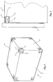
- a conventional parallelepiped container 1 has two side surfaces 2 extending parallel to each other, two end surfaces 2' extending perpendicularly to said side surfaces 2, an upper surface 3 and a bottom surface (not shown in Figure 1) extending parallel to said upper surface 3.
- the length of a side surface 2 is greater than the width of an end surface 2'.
- coupling pieces 4 are conventionally provided in the corner points of the container, said coupling pieces in three surfaces extending perpendicularly to each other being provided with openings 5 - 7 for inserting coupling means, which form part of a lifting or carrying device of some kind, by means of which the container in question can be lifted and/or moved, or which form part of a vehicle and by means of which the container in question can be secured to the vehicle.
- a carrying device is coupled to said fork-lift truck, in such a manner that said carrying device is movable upwards and downwards in a conventional manner by means of the lifting mechanism of the fork-lift truck or the like.
- the carrying device is provided with coupling means, which can be inserted into the coupling pieces of a container in order to secure said container to the carrying device in question.
- FIG 2 diagrammatically shows a part of a frame 8 of such a carrying device to be coupled to a fork-lift truck or the like.
- the frame 8 is thereby provided near its upper ends with two spaced-apart, hook-shaped coupling means 9, which can be inserted into coupling pieces 4 provided near the upper edge of the respective container 1, namely through the openings 6, whilst the ends of said hook-shaped coupling means will thereby come to lie in the openings 5, as will be apparent from Figure 2.
- the container thereby butts against a cross beam of the frame 8 near its bottom side.
- An advantage of this construction is that there are no parts which project beyond the upper surface 3 of the container, so that it is possible to place a second container on top of the container that is coupled to the frame.
- a second container placed on top of the container that is coupled to the frame 8 is not secured in any way, however, with the attendant risk that the upper container may fall off the lower container when two containers placed one on top of the other in this manner are being moved by means of the fork-lift truck or the like, with all its consequent dangers.
- Figure 3 shows an embodiment wherein the frame 8 of the carrying device is provided with arms 10 extending above the container 1 coupled to the frame 8, to which arms 10 coupling means having unround heads 11 and being pivotable about vertical axes are secured.
- said unround heads 11 may be passed through the holes 5 located at the upper sides of the coupling pieces 4, after which the coupling pieces may be pivoted into a second position, such that the unround heads 11 cannot be retracted in upward direction from the respective holes 5 any more.
- the frame 8 is provided with hook-shaped coupling means 12 fixedly connected to the frame, which may be passed from above through the openings 5 of coupling pieces 4 provided at the upper side of the container. Furthermore the frame is provided with pins 13 which are movable to and from in the direction of the arrow A by setting means not shown, which pins may be passed through the openings 6 of the coupling pieces 4.
- Figures 5 and 6 show an embodiment wherein two containers 1 and 1' placed one on top of the other can be secured with respect to the frame 8 of the carrying device. It is this embodiment, which is known per se, that is referred to in the preamble of claim 1 of the present application.
- hooks 14 are secured to the frame 8 of the carrying device, said hooks 14 corresponding with the hooks 9 of the embodiment shown in Figure 2, whereby a lower container 1, more in particular the coupling pieces 4 of said lower container 1, can be coupled to the frame 8 of the device by means of said hooks 14 in the manner described with reference to Figure 2.
- the frame 8 is furthermore provided with hook-shaped coupling means 15, which can be moved, by setting means not shown, parallel to a side surface 2 of the container 1', as indicated by means of the double arrows B, and whose insert ends may be inserted into or retracted from openings 7 of coupling pieces 4' in the end surfaces 2, said coupling pieces 4' being located near the lower corner points of a container 1' placed on top of the lower container 1.
- a drawback of this embodiment is that when such a carrying device is used it is not possible to place containers in line, with their side surfaces 2' butting against each other, or to pick up containers which are placed with their side surfaces 2' butting against each other by means of the carrying device.
- the object of the invention is to obtain a carrying device to which two containers placed one on top of the other can be secured in a safe manner, whereby the insert ends of the coupling means co-operating with the lower container and the insert ends of the coupling means co-operating with the upper container can be inserted into the openings in the surfaces, located one above the other, of the respective coupling pieces of the containers in question, as a result of which it becomes possible to place the containers in firmly abutting relationship with their end surfaces and/or side surfaces, or to pick up containers that firmly abut against each other by means of the carrying device.
- this may be achieved in that the two coupling means are placed one above the other, being pivotally coupled with their ends remote from the insert ends to be inserted into the coupling pieces of the containers to a coupling arm which is pivotally coupled to the frame of the carrying device between the coupling points of said coupling means.
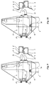
- the frame 8 is provided with two pairs of coupling means, which are spaced apart by a distance which at least substantially corresponds with the distance between two coupling pieces 4 provided in the corner points of a container.
- Each pair of coupling means is provided with a first coupling means 16, which is built up of two substantially L-shaped plates 17 extending parallel to each other.
- the legs of said plates 17, which extend substantially horizontally, are coupled to the lower end of a coupling arm 19 by means of a pivot pin 18.
- the coupling arm 19 is pivotally coupled to the frame 8 of the carrying device by means of a pin 20 extending parallel to the pin 18.
- the substantially vertically extending legs of the plates 17 are interconnected by means of a connecting piece 20.
- a hook-shaped insert end 21 of the coupling means 16 is located at the side of the coupling means 16 remote from the pivot pin 18.
- One end of a coupling means 23 located above the coupling means 16 is coupled to the end of the coupling arm 19 projecting above the pin 20 by means of a pivot pin 22 extending parallel to the pins 18 and 20.
- Said coupling means 23 is built up of two plate-shaped parts 24 and a hook-shaped insert end 25 located above the insert end 21.
- Stops 26 and 27, which are only schematically indicated in the Figure, are provided near the pivot pins 18 and 22 respectively, said stops 26 and 27 bounding the pivoting movement of the coupling arm 19 about the pin 20.
- compression springs 28 and 29 are provided between the plate-shaped parts 17 of the coupling means 16 and the part of the coupling means 23 located between said plate-shaped parts, said compression springs 28 and 29 enabling a certain pivoting of the upper coupling means, in particular of the insert end 25 of said coupling means, in horizontal direction with respect to the insert end 21 of the lower coupling means 16, as is indicated by means of the double arrow C.
- a setting cylinder 30 located above the coupling means 23 is furthermore provided between the plate-shaped parts 17 of the coupling means 16.
- the piston rod 31 of said setting cylinder is pivotally coupled to the upper coupling means 23 by means of a pivot pin 32.
- An upwardly extending rod 33 is attached to the upper end of the setting cylinder 33, said rod being passed with a certain amount of play through a hole provided in the plate 20.
- a compression spring 35 is provided between the plate 20 and a retaining member 34 provided on the upper end of the rod 32.
- the lower coupling means is supported at its bottom side, between its ends, by a preferably slightly resilient support 36 attached to the frame 8.
- the insert ends 21 and 25 located one above the other of the coupling means 16 and 23 can be moved in the direction of the arrow E by means of a vehicle supporting the frame 8, in order to be inserted into respectively the openings 6 located one above the other of a coupling piece 4 located near the upper edge of a lower container 1 and a coupling piece 4' located near the bottom edge of a container 1' placed on top thereof.
- the insert ends 21 and 25 may remain freely adjustable during insertion, whilst the upper insert end 25 may be pushed downwards by means of the setting cylinder 30 following insertion, as a result of which a firm engagement of the hook-shaped insert ends 21 and 25 into the openings 5 of the coupling pieces 4 and 4' will be effected.
- the coupling pieces 4 and 4' of the containers placed one above the other may be slightly shifted in the longitudinal direction of the respective side face with respect to each other, as is schematically indicated in Figure 8.
- Such a lateral displacement may be set off by the above-described pivotability of the upper coupling piece 23 with respect to the lower coupling piece 16 in the direction according to the arrow C.
- the free end of said insert end is pointed, as is apparent in particular from Figures 7 and 8.
- the containers may have shifted in a direction transversely to the side surfaces provided with the holes 6 into which the insert ends 25 and 21 are inserted.
- Such a displacement may be set off by pivoting of the coupling arm 19 about the pivot pin 20, whereby the coupling means 16 and 23 can slightly move in a direction perpendicularly to the surfaces of the containers provided with the openings into which the insert ends must be inserted.
- such a movement of the coupling means 16 and 23 is limited by stops 26 and 27 co-operating with the coupling arm 19.
- the dimensions of the coupling pieces with the holes provided therein are not always the same for all containers. It must be possible to move the free ends of the insert ends 21 and 25 apart by means of the setting cylinder 30, over such a distance that it can be ensured, also with the largest coupling pieces, that the insert ends 21 and 25 can be retracted from the coupling pieces without impediment.
- Figure 11 shows a further embodiment.
- those parts whose functions correspond with the parts described above with reference to Figures 7 - 10 have been given the same reference numerals as in the said Figures 7 - 10.
- This embodiment does not comprise a setting cylinder 30. Furthermore compression springs 42 are provided between the coupling means 23 and parts 40 and 41 of the coupling means 16 extending above and under said coupling means 23, so that the coupling means 23 can move out resiliently in horizontal as well as in vertical direction with respect to the coupling means 16.
- the insert end 43 of the upper coupling means 23 is pivotable about the longitudinal axis of the coupling means 23 by setting means not shown. Said insert end is thereby provided with an unround head 44, as will be apparent in particular from Figure 12. In a first position of said unround head the unround head may be passed through the opening 6 of the coupling piece 4 of an upper container, to extend into the interior of said coupling piece, whereupon the head of said insert end can be moved into another position in order to secure said insert end to the coupling piece in question.
- this second embodiment of the coupling means will be essentially similar to the operation of the coupling means as explained with reference to Figures 7 - 10.
Landscapes
- Engineering & Computer Science (AREA)
- Transportation (AREA)
- Structural Engineering (AREA)
- Civil Engineering (AREA)
- Life Sciences & Earth Sciences (AREA)
- Geology (AREA)
- Mechanical Engineering (AREA)
- Handcart (AREA)
- Pallets (AREA)
Applications Claiming Priority (2)
| Application Number | Priority Date | Filing Date | Title |
|---|---|---|---|
| NL9301385A NL9301385A (nl) | 1993-08-10 | 1993-08-10 | Draaginrichting voor het opnemen van een tweetal boven elkaar geplaatste containers. |
| NL9301385 | 1993-08-10 |
Publications (1)
| Publication Number | Publication Date |
|---|---|
| EP0638512A1 true EP0638512A1 (de) | 1995-02-15 |
Family
ID=19862745
Family Applications (1)
| Application Number | Title | Priority Date | Filing Date |
|---|---|---|---|
| EP94202192A Withdrawn EP0638512A1 (de) | 1993-08-10 | 1994-07-27 | Tragvorrichtung zur Aufnahme von zwei aufeinander gestapelten Behältern |
Country Status (2)
| Country | Link |
|---|---|
| EP (1) | EP0638512A1 (de) |
| NL (1) | NL9301385A (de) |
Cited By (5)
| Publication number | Priority date | Publication date | Assignee | Title |
|---|---|---|---|---|
| EP0701964A1 (de) * | 1994-08-19 | 1996-03-20 | Elmhults Konstruktions AB | Container-Hebegerät mit seitlicher Aufnahme |
| WO1997030928A1 (en) * | 1996-02-21 | 1997-08-28 | Hyco-Cascade Pty. Ltd. | Container handling assembly |
| NL1004817C2 (nl) * | 1996-12-18 | 1998-06-19 | Smits Intellectual Property N | Draaginrichting voor het opnemen van een tweetal boven elkaar geplaatste containers. |
| NL1010956C2 (nl) * | 1999-01-05 | 2000-07-06 | Smits Intellectual Property N | Draaginrichting voor het opnemen van een tweetal boven elkaar geplaatste containers. |
| CN110431102A (zh) * | 2017-03-31 | 2019-11-08 | 艾玛斯布达有限公司 | 用于提升联运集装箱的侧向提升吊具以及操作侧向提升吊具的方法 |
Citations (2)
| Publication number | Priority date | Publication date | Assignee | Title |
|---|---|---|---|---|
| DE3741714A1 (de) * | 1987-12-09 | 1989-06-22 | Asea Brown Boveri | Handhabungsvorrichtung |
| JPH04361984A (ja) * | 1991-06-07 | 1992-12-15 | Yamatomi Sangyo Kk | ブロックの移動方法とその装置 |
-
1993
- 1993-08-10 NL NL9301385A patent/NL9301385A/nl not_active Application Discontinuation
-
1994
- 1994-07-27 EP EP94202192A patent/EP0638512A1/de not_active Withdrawn
Patent Citations (2)
| Publication number | Priority date | Publication date | Assignee | Title |
|---|---|---|---|---|
| DE3741714A1 (de) * | 1987-12-09 | 1989-06-22 | Asea Brown Boveri | Handhabungsvorrichtung |
| JPH04361984A (ja) * | 1991-06-07 | 1992-12-15 | Yamatomi Sangyo Kk | ブロックの移動方法とその装置 |
Non-Patent Citations (1)
| Title |
|---|
| PATENT ABSTRACTS OF JAPAN vol. 17, no. 233 (M - 1407) 12 May 1993 (1993-05-12) * |
Cited By (10)
| Publication number | Priority date | Publication date | Assignee | Title |
|---|---|---|---|---|
| EP0701964A1 (de) * | 1994-08-19 | 1996-03-20 | Elmhults Konstruktions AB | Container-Hebegerät mit seitlicher Aufnahme |
| WO1997030928A1 (en) * | 1996-02-21 | 1997-08-28 | Hyco-Cascade Pty. Ltd. | Container handling assembly |
| EP1005437A4 (de) * | 1996-02-21 | 2000-06-07 | Hyco Cascade Pty Ltd | Anordnung zum handhaben von kontainern |
| NL1004817C2 (nl) * | 1996-12-18 | 1998-06-19 | Smits Intellectual Property N | Draaginrichting voor het opnemen van een tweetal boven elkaar geplaatste containers. |
| NL1010956C2 (nl) * | 1999-01-05 | 2000-07-06 | Smits Intellectual Property N | Draaginrichting voor het opnemen van een tweetal boven elkaar geplaatste containers. |
| EP1018481A1 (de) * | 1999-01-05 | 2000-07-12 | Smits Intellectual Property N.V. | Tragvorrichtung zur Aufnahme von zwei aufeinander gestapelten Behältern |
| US6431625B1 (en) | 1999-01-05 | 2002-08-13 | Smits Intellectual Property N.V. | Apparatus for picking up two containers placed one on top of another |
| CN110431102A (zh) * | 2017-03-31 | 2019-11-08 | 艾玛斯布达有限公司 | 用于提升联运集装箱的侧向提升吊具以及操作侧向提升吊具的方法 |
| US10913642B2 (en) | 2017-03-31 | 2021-02-09 | Elme Spreader Ab | Side lift spreader for lifting intermodal containers, and method of operating a side lift spreader |
| CN110431102B (zh) * | 2017-03-31 | 2021-04-16 | 艾玛斯布达有限公司 | 用于提升联运集装箱的侧向提升吊具以及操作侧向提升吊具的方法 |
Also Published As
| Publication number | Publication date |
|---|---|
| NL9301385A (nl) | 1995-03-01 |
Similar Documents
| Publication | Publication Date | Title |
|---|---|---|
| US6533526B2 (en) | Fork lift rack displacement device | |
| CA2216121C (en) | Transport and storage container | |
| CA1284118C (en) | Interlocking adapter casting | |
| US5588372A (en) | Stackable dispensing apparatus for wire reels | |
| EP0552153B1 (de) | Behälter | |
| US5644992A (en) | Collapsible flatrack with ramp end walls | |
| US8201701B2 (en) | Folding container | |
| US5404821A (en) | Pallet having posts with jack screw lock | |
| CA2440589A1 (en) | Vertically stabilized shelf bracket assembly | |
| EP0638512A1 (de) | Tragvorrichtung zur Aufnahme von zwei aufeinander gestapelten Behältern | |
| US5308584A (en) | Cuvette matrix tray | |
| US5111952A (en) | Lid with a handle for containers of accumulators | |
| EP0560607A1 (de) | Hebevorrichtung | |
| US4387484A (en) | Supporting bracket for side handles of utensils | |
| US4711355A (en) | Stackable box | |
| EP0335472A1 (de) | Tragbare Stütz- und Hebevorrichtung für eine Plattform | |
| EP1018481B1 (de) | Tragvorrichtung zur Aufnahme von zwei aufeinander gestapelten Behältern | |
| EP0163621A1 (de) | Klappbarer und verstellbarer Stützfuss für einen Lasttragerahmen | |
| CA1324157C (en) | Apparatus for opening and holding a frame and a method of mounting an optical element in a frame | |
| GB2076371A (en) | A collapsible flat | |
| JP2001213504A (ja) | ラック装置 | |
| CN212830515U (zh) | 一种方便组装的集装箱角件 | |
| JP2561795B2 (ja) | フレーム付きパレット | |
| US20050161952A1 (en) | Connection device, box and clamp | |
| EP0543474A1 (de) | Palettengreifvorrichtung |
Legal Events
| Date | Code | Title | Description |
|---|---|---|---|
| PUAI | Public reference made under article 153(3) epc to a published international application that has entered the european phase |
Free format text: ORIGINAL CODE: 0009012 |
|
| AK | Designated contracting states |
Kind code of ref document: A1 Designated state(s): AT BE CH DE DK ES FR GB GR IE IT LI LU MC NL PT SE |
|
| RAX | Requested extension states of the european patent have changed |
Free format text: SI PAYMENT 940727 |
|
| 17P | Request for examination filed |
Effective date: 19950808 |
|
| 17Q | First examination report despatched |
Effective date: 19970606 |
|
| STAA | Information on the status of an ep patent application or granted ep patent |
Free format text: STATUS: THE APPLICATION IS DEEMED TO BE WITHDRAWN |
|
| 18D | Application deemed to be withdrawn |
Effective date: 19971217 |