EP0560607A1 - Hebevorrichtung - Google Patents
Hebevorrichtung Download PDFInfo
- Publication number
- EP0560607A1 EP0560607A1 EP93301859A EP93301859A EP0560607A1 EP 0560607 A1 EP0560607 A1 EP 0560607A1 EP 93301859 A EP93301859 A EP 93301859A EP 93301859 A EP93301859 A EP 93301859A EP 0560607 A1 EP0560607 A1 EP 0560607A1
- Authority
- EP
- European Patent Office
- Prior art keywords
- slot
- depending
- bridging
- bridging member
- trunnion
- Prior art date
- Legal status (The legal status is an assumption and is not a legal conclusion. Google has not performed a legal analysis and makes no representation as to the accuracy of the status listed.)
- Withdrawn
Links
- 238000000034 method Methods 0.000 description 2
- 125000006850 spacer group Chemical group 0.000 description 2
- 230000000694 effects Effects 0.000 description 1
- 230000005484 gravity Effects 0.000 description 1
- 230000004048 modification Effects 0.000 description 1
- 238000012986 modification Methods 0.000 description 1
- 239000011824 nuclear material Substances 0.000 description 1
- 230000000284 resting effect Effects 0.000 description 1
- 230000000717 retained effect Effects 0.000 description 1
Images


Classifications
-
- B—PERFORMING OPERATIONS; TRANSPORTING
- B66—HOISTING; LIFTING; HAULING
- B66C—CRANES; LOAD-ENGAGING ELEMENTS OR DEVICES FOR CRANES, CAPSTANS, WINCHES, OR TACKLES
- B66C1/00—Load-engaging elements or devices attached to lifting or lowering gear of cranes or adapted for connection therewith for transmitting lifting forces to articles or groups of articles
- B66C1/10—Load-engaging elements or devices attached to lifting or lowering gear of cranes or adapted for connection therewith for transmitting lifting forces to articles or groups of articles by mechanical means
- B66C1/105—Lifting beam permitting to depose a load through an opening
-
- B—PERFORMING OPERATIONS; TRANSPORTING
- B66—HOISTING; LIFTING; HAULING
- B66C—CRANES; LOAD-ENGAGING ELEMENTS OR DEVICES FOR CRANES, CAPSTANS, WINCHES, OR TACKLES
- B66C1/00—Load-engaging elements or devices attached to lifting or lowering gear of cranes or adapted for connection therewith for transmitting lifting forces to articles or groups of articles
- B66C1/10—Load-engaging elements or devices attached to lifting or lowering gear of cranes or adapted for connection therewith for transmitting lifting forces to articles or groups of articles by mechanical means
- B66C1/62—Load-engaging elements or devices attached to lifting or lowering gear of cranes or adapted for connection therewith for transmitting lifting forces to articles or groups of articles by mechanical means comprising article-engaging members of a shape complementary to that of the articles to be handled
- B66C1/66—Load-engaging elements or devices attached to lifting or lowering gear of cranes or adapted for connection therewith for transmitting lifting forces to articles or groups of articles by mechanical means comprising article-engaging members of a shape complementary to that of the articles to be handled for engaging holes, recesses, or abutments on articles specially provided for facilitating handling thereof
Definitions
- the invention relates to a lifting device for engaging trunnions or the like of objects to be lifted and more particularly, but not exclusively, to a lifting device for transport flasks for containing nuclear material.
- a conventional lifting device usually comprises a beam having side arms depending from each of its ends, and shackles are usually employed to join the side arms to the beam.
- a shackled joint is extremely flexible and, consequently, the positional adjustment of one side arm is not easily transferred through the beam structure to effect a corresponding adjustment of the other side arm.
- a lifting device for engaging trunnions orthe like of objects to be lifted, the device comprising a beam having at least two substantially rigid depending members, each depending member having at least one open slot at its lower end so as to drop downwardly over a respective trunnion, and a respective removable member for bridging across a respective said slot under the trunnion, the removable member being engageable with the slot so as to support the trunnion when the beam is lifted.
- each depending member is supported by a pin joint from the beam, and pivotal movement of the depending member is substantially restricted by the beam.
- the slot extends longitudinally with respect to the respective depending member.
- the slot near the lower end thereof defines opposing shoulders for engaging the bridging member.
- the bridging member is pivotally connected to a pivot mechanism at the respective depending member, the pivot mechanism being operable to move the bridging member to extreme positions to and from the slot.
- the extreme positions of the bridging member are maintained by the weight of the bridging member acting on the pivot mechanism.
- a latching means engageable with the pivot mechanism additionally maintains the bridging member engaged in the slot during lifting of the device.
- a lifting device 10 comprising a bridge beam 12 having two identical depending members in the form of side arms 14 in opposing relationship.
- the beam 12 comprises two elongated parallel plates 18,20, the plates 18,20 being held spaced apart at their ends by respective spacer plates 22,24 which locate in close fitting relationship about a respective side arm 14.
- Each side arm 14 is supported by a respective pin 30 held at each end in the spacer plates 22,24, the width of the side arms 14 being such that pivotal movement of the side arms 14 on the pins 30 is substantially restricted by the plates 18,20.
- Alifting structure 32, secured between the plates 18,20 by pins 33 is shaped at 35 to accommodate a conventional crane hook or the like (not shown).
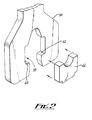
- Each side arm 14 has a lower portion 36 defining an open longitudinal slot 38.
- the lower end of the slot 38 is shaped so as to define opposing shoulders 40, 42, the upper end of the slot 38 being shaped so as to locate a respective trunnion or the like (not shown) of an object to be lifted.
- Arespective removable bridging member 44 (only one is shown) is locatable on the shoulders 40,42 so as to bridge the slot 38, the bridging member 44 being shaped so as to accommodate and support the underside of the trunnion when the beam 12 is lifted.
- Each bridging member 44 is movable by a respective pivot mechanism 50 to and from the shoulders 40,42.
- the bridging member 44 is shown located within the slot 38 and rests on the shoulders 40,42.
- Two side plates 58,60 extend perpendicularly from the lower portion 36, one on either side of the slot 38, each side plate 58,60 being fitted with an outwardly extending handle 62,64 respectively.
- the bridging member 44 is movable from a 'closed' position, where it locates on the shoulders 40,42 (as shown), to an 'open' position remote from the shoulders 40,42, and vice versa by means of the pivot mechanism 50.
- the pivot mechanism 50 has two pegs 66,68 attached one each side of the bridging member 44 and which connect the bridging member 44 to pivot arms 70,72 respectively.
- Each pivot arm 70,72 has a second peg 74,76 respectively connected to respective pivot stubs 78,80 which in turn are connected at their opposite ends to the side plates 58,60.
- a pivot handle 82 is connected between and protrudes beyond the pivot arms 70,72 at 81,83.
- the pivot mechanism 50 is balanced so that the extreme positions of the bridging member 44 in the 'open' and 'closed' positions are maintained by the weight of the bridging member 44 acting on the pivot mechanism 50.
- the bridging member 44 is additionally retained on the shoulders 40,42 by a latching device 71 engageable with the pivot handle 82.
- the latching device 71 comprises two spaced apart latching arms 84,86, each of which has a concave portion 85 which engages at 81,83 respectively with the protruding ends of the pivot handle 82 and a lower relieved end 87 with a corner chamfer 89.
- the ends 87 are arranged such that they engage the pivot handle 82 when it is raised from the "open" position, and deflect the latching arms 84, 86 backwardly from where they return under gravity to latch the pivot handle 82 as shown in Figure 5.
- the latching arms 84,86 are connected to each other by a latching handle 88, and are connected to the side plates 58,60 by respective pegs 90,92.
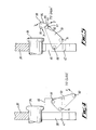
- Figure 4 shows the lower portion 36 of the side arm 14 resting on a lifting trunnion 94 with the bridging member44 in the'open' position remote from the shoulder 42 and the pivot handle 82 in its lowermost position. Raising the pivot handle 82 in the direction of the arrow X causes the pivot arm 70 to pivot about the peg 74 thereby moving the bridging member 44 to the 'closed' position where it rests on the shoulders 42,44 (as shown in Figure 5).
- the pivot handle 82 is in its uppermost position and is engaged by the concave latching portion 85 of the latching arm 84 to prevent the bridging member 44 from being inadvertently removed from the closed position during raising and lowering of the beam 12 (not shown).
- the latching handle 88 is pushed upwardly in the direction of the arrow Y so as to cause the latching arm 84 to pivot about the peg 90.
- the concave latching portion 85 disengages from the pivot handle 82 and the pivot handle 82 is pulled downwardly in the direction of the arrow Z thereby moving the bridging member 44 to the 'open' position.
- the beam 12 is lifted by means of a hook suspended from an overhead crane (not shown) attached to the lifting structure 32. Both of the bridging members 44 are in the 'open' position.
- the lifting device 10 is manoeuvred by the overhead crane into a position such that the slots 38 of the side arms 14 are approximately aligned over the lifting trunnions 94 of an object such as a flask to be lifted.
- a single operator can adjust the position of one of the side arms 14 by means of the handles 62,64 so that the slot 38 can drop down over its respective lifting trunnion 94.
- This positional adjustment is transferred through the structure of the lifting device 10 due to its relative rigidity, so that the slot 38 of the other side arm 14 also drops down over its respective lifting trunnion 94 as the device 10 is lowered until the closed upper ends of the slots 38 rest on their respective lifting trunnions 94.
- the operator moves the first bridging member 44 into its'closed' position by operating the pivot handle 82 as described above in relation to Figures 4 and 5.
- the operator then moves to the other side arm 14 and repeats the aforementioned procedure for the second bridging member 44 and its respective pivot handle 82.
- the device 10 may then be lifted and moved to a desired location by the overhead crane, the flask trunnions 94 being engaged and supported by the bridging members 44 and the weight of the flask being transferred through the bridging members 44 to the shoulders 40,42 of the slots 38 as the lifting device 10 rises.
- the device 10 is lowered by the overhead crane so that once again the closed ends of the slots 38 rest on their respective lifting trunnions 94.
- the operator then moves to one of the side arm 14, operates the latching handle 88 to disengage the pivot handle 82 from the latching arms 84,86 and operates the pivot handle 82 to move the bridging member 44 to the 'open' position.
- the operator next moves to the other side arm 14 and repeats the aforementioned procedure in order to move the respective bridging member 44 to the 'open' position.
- the device 10 is lifted once again by the overhead crane and may be positioned over another flask which requires to be moved.
- the relative rigidly of the lifting device of the invention enables a single operator to connect and disconnect the side arms of the device to an object to be lifted.
- the device may have more than two depending members and/or more than two slots to engage a corresponding number of trunnions.
Landscapes
- Engineering & Computer Science (AREA)
- Mechanical Engineering (AREA)
- Load-Engaging Elements For Cranes (AREA)
Applications Claiming Priority (2)
| Application Number | Priority Date | Filing Date | Title |
|---|---|---|---|
| GB929205257A GB9205257D0 (en) | 1992-03-11 | 1992-03-11 | A lifting device |
| GB9205257 | 1992-03-11 |
Publications (1)
| Publication Number | Publication Date |
|---|---|
| EP0560607A1 true EP0560607A1 (de) | 1993-09-15 |
Family
ID=10711890
Family Applications (1)
| Application Number | Title | Priority Date | Filing Date |
|---|---|---|---|
| EP93301859A Withdrawn EP0560607A1 (de) | 1992-03-11 | 1993-03-11 | Hebevorrichtung |
Country Status (4)
| Country | Link |
|---|---|
| EP (1) | EP0560607A1 (de) |
| JP (1) | JPH06135674A (de) |
| KR (1) | KR930019542A (de) |
| GB (1) | GB9205257D0 (de) |
Cited By (12)
| Publication number | Priority date | Publication date | Assignee | Title |
|---|---|---|---|---|
| GB2365847A (en) * | 2000-06-29 | 2002-02-27 | Aarre Arne | Arrangement at a lifting hook |
| AT409368B (de) * | 1998-12-16 | 2002-07-25 | Stahl Ges M B H R | Vorrichtung zum anschliessen eines in ein tauchbad einsetzbaren werkstückes an ein hebezeug |
| EP0949182A3 (de) * | 1998-04-08 | 2002-12-11 | KEURO Besitz GmbH & Co. EDV-Dienstleistungs KG | Transportvorrichtung für Behältnisse zur Aufnahme von Material |
| US7134701B1 (en) | 2003-01-03 | 2006-11-14 | Ronning James M | Frame for lifting beams and other elongated loads |
| US7296630B2 (en) * | 2005-02-25 | 2007-11-20 | Blohm + Voss Repair Gmbh | Hands-free bail-elevator locking device with combined power/control connector, bail spreader and method for use |
| FR3032954A1 (fr) * | 2015-02-23 | 2016-08-26 | Airbus Defence & Space Sas | Dispositif de levage de charges |
| JP2016183876A (ja) * | 2015-03-25 | 2016-10-20 | 三菱重工業株式会社 | 吊構造 |
| US9476268B2 (en) | 2012-10-02 | 2016-10-25 | Weatherford Technology Holdings, Llc | Compensating bails |
| WO2018211462A1 (en) * | 2017-05-19 | 2018-11-22 | Golden Project Di Aldo Chistè | Fast hooking/unhooking element |
| CN109534151A (zh) * | 2017-09-22 | 2019-03-29 | 中国二十冶集团有限公司 | 一种激光焊机吊装工具 |
| US10934136B1 (en) * | 2015-08-28 | 2021-03-02 | Eric Andrew Baier | Hardtop removal bracket and methods of use thereof |
| CN112758806A (zh) * | 2020-12-30 | 2021-05-07 | 中国核工业华兴建设有限公司 | 一种装配式混凝土构件起吊系统连接装置和起吊操作方法 |
Families Citing this family (3)
| Publication number | Priority date | Publication date | Assignee | Title |
|---|---|---|---|---|
| KR100885783B1 (ko) * | 2007-01-23 | 2009-02-26 | 주식회사 하이닉스반도체 | 플래시 메모리 장치 및 동작 방법 |
| JP6316767B2 (ja) * | 2015-03-23 | 2018-04-25 | 日立Geニュークリア・エナジー株式会社 | キャスク吊り具 |
| JP6762517B2 (ja) * | 2018-10-16 | 2020-09-30 | 株式会社Winビジネスデベロップメント | 搬送用架台 |
Citations (9)
| Publication number | Priority date | Publication date | Assignee | Title |
|---|---|---|---|---|
| DE1252390B (de) * | 1967-10-19 | |||
| US3625558A (en) * | 1970-11-10 | 1971-12-07 | George F Johnson | Automatic hoist coupling device |
| DE2338480A1 (de) * | 1973-07-28 | 1975-02-13 | Kernforschung Gmbh Ges Fuer | Einrichtung zum transportieren von radioaktiven abfaellen |
| FR2243901A1 (en) * | 1973-09-13 | 1975-04-11 | Gautier Jean Louis | Material roll handling device - jaws automatically engage ends of carrier spindle as device is lowered |
| DE2438172A1 (de) * | 1974-08-08 | 1976-02-19 | Hugo Wupper | Am lasthaken eines kranes anhaengbares lastaufnahmemittel |
| US4108485A (en) * | 1977-03-22 | 1978-08-22 | Stearns-Roger Corporation | Redundant lift beam assembly |
| FR2455203A1 (fr) * | 1979-04-26 | 1980-11-21 | Ecopol | Dispositif de fixation pour le levage d'un fut de beton contenant des dechets radioactifs et procede de montage de ce dispositif sur les futs contenant les dechets radioactifs |
| US4336460A (en) * | 1979-07-25 | 1982-06-22 | Nuclear Assurance Corp. | Spent fuel cask |
| DE3421774A1 (de) * | 1984-06-12 | 1985-12-12 | Kraftwerk Union AG, 4330 Mülheim | Gehaenge fuer den transport schwerer lasten mit einem kran |
-
1992
- 1992-03-11 GB GB929205257A patent/GB9205257D0/en active Pending
-
1993
- 1993-03-11 KR KR1019930003589A patent/KR930019542A/ko not_active Withdrawn
- 1993-03-11 EP EP93301859A patent/EP0560607A1/de not_active Withdrawn
- 1993-03-11 JP JP5077607A patent/JPH06135674A/ja active Pending
Patent Citations (9)
| Publication number | Priority date | Publication date | Assignee | Title |
|---|---|---|---|---|
| DE1252390B (de) * | 1967-10-19 | |||
| US3625558A (en) * | 1970-11-10 | 1971-12-07 | George F Johnson | Automatic hoist coupling device |
| DE2338480A1 (de) * | 1973-07-28 | 1975-02-13 | Kernforschung Gmbh Ges Fuer | Einrichtung zum transportieren von radioaktiven abfaellen |
| FR2243901A1 (en) * | 1973-09-13 | 1975-04-11 | Gautier Jean Louis | Material roll handling device - jaws automatically engage ends of carrier spindle as device is lowered |
| DE2438172A1 (de) * | 1974-08-08 | 1976-02-19 | Hugo Wupper | Am lasthaken eines kranes anhaengbares lastaufnahmemittel |
| US4108485A (en) * | 1977-03-22 | 1978-08-22 | Stearns-Roger Corporation | Redundant lift beam assembly |
| FR2455203A1 (fr) * | 1979-04-26 | 1980-11-21 | Ecopol | Dispositif de fixation pour le levage d'un fut de beton contenant des dechets radioactifs et procede de montage de ce dispositif sur les futs contenant les dechets radioactifs |
| US4336460A (en) * | 1979-07-25 | 1982-06-22 | Nuclear Assurance Corp. | Spent fuel cask |
| DE3421774A1 (de) * | 1984-06-12 | 1985-12-12 | Kraftwerk Union AG, 4330 Mülheim | Gehaenge fuer den transport schwerer lasten mit einem kran |
Cited By (14)
| Publication number | Priority date | Publication date | Assignee | Title |
|---|---|---|---|---|
| EP0949182A3 (de) * | 1998-04-08 | 2002-12-11 | KEURO Besitz GmbH & Co. EDV-Dienstleistungs KG | Transportvorrichtung für Behältnisse zur Aufnahme von Material |
| AT409368B (de) * | 1998-12-16 | 2002-07-25 | Stahl Ges M B H R | Vorrichtung zum anschliessen eines in ein tauchbad einsetzbaren werkstückes an ein hebezeug |
| GB2365847A (en) * | 2000-06-29 | 2002-02-27 | Aarre Arne | Arrangement at a lifting hook |
| US7134701B1 (en) | 2003-01-03 | 2006-11-14 | Ronning James M | Frame for lifting beams and other elongated loads |
| US7296630B2 (en) * | 2005-02-25 | 2007-11-20 | Blohm + Voss Repair Gmbh | Hands-free bail-elevator locking device with combined power/control connector, bail spreader and method for use |
| US9951570B2 (en) | 2012-10-02 | 2018-04-24 | Weatherford Technology Holdings, Llc | Compensating bails |
| US9476268B2 (en) | 2012-10-02 | 2016-10-25 | Weatherford Technology Holdings, Llc | Compensating bails |
| WO2016135091A1 (fr) * | 2015-02-23 | 2016-09-01 | Airbus Defence & Space Sas | Dispositif de levage de charges |
| FR3032954A1 (fr) * | 2015-02-23 | 2016-08-26 | Airbus Defence & Space Sas | Dispositif de levage de charges |
| JP2016183876A (ja) * | 2015-03-25 | 2016-10-20 | 三菱重工業株式会社 | 吊構造 |
| US10934136B1 (en) * | 2015-08-28 | 2021-03-02 | Eric Andrew Baier | Hardtop removal bracket and methods of use thereof |
| WO2018211462A1 (en) * | 2017-05-19 | 2018-11-22 | Golden Project Di Aldo Chistè | Fast hooking/unhooking element |
| CN109534151A (zh) * | 2017-09-22 | 2019-03-29 | 中国二十冶集团有限公司 | 一种激光焊机吊装工具 |
| CN112758806A (zh) * | 2020-12-30 | 2021-05-07 | 中国核工业华兴建设有限公司 | 一种装配式混凝土构件起吊系统连接装置和起吊操作方法 |
Also Published As
| Publication number | Publication date |
|---|---|
| GB9205257D0 (en) | 1992-04-22 |
| KR930019542A (ko) | 1993-10-18 |
| JPH06135674A (ja) | 1994-05-17 |
Similar Documents
| Publication | Publication Date | Title |
|---|---|---|
| US4526344A (en) | Auxiliary lift adapter | |
| US5382131A (en) | Tool for manipulating heavy objects | |
| SE438475B (sv) | Lasanordning for lastningsanleggning | |
| US3278045A (en) | Counterweight support mechanism | |
| EP0928278B1 (de) | Vorrichtung zum kippen von behältern | |
| US4105218A (en) | Portable pallet carriers | |
| US4000923A (en) | Gabion basket emplacement apparatus and method | |
| US4133570A (en) | Hoisting apparatus having improved clamping means | |
| JP2902589B2 (ja) | 吊りクランプ | |
| GB2060557A (en) | Lifting device | |
| JPH06135674A (ja) | 巻上げ装置 | |
| US6273667B2 (en) | Apparatus for inverting containers | |
| US4600168A (en) | Ground handling apparatus for a helicopter | |
| GB2187705A (en) | Lifting apparatus and method | |
| US5429210A (en) | Adjustable height wagon | |
| GB2076371A (en) | A collapsible flat | |
| WO1996026386A1 (en) | Cradle support handler | |
| US4579235A (en) | Crane boom stowing apparatus | |
| US3861732A (en) | Adjustable gripper apparatus | |
| AU594786B2 (en) | Lifting device for containers | |
| US3252729A (en) | Sling carrier | |
| EP0638512A1 (de) | Tragvorrichtung zur Aufnahme von zwei aufeinander gestapelten Behältern | |
| JPH102990A (ja) | チャンネルボックス用グラップル | |
| US5685590A (en) | Carriage for selectively and remote positively suspendingly engaging and disengaging a load in transporting same from one location to another | |
| SU1440841A1 (ru) | Грузозахватное устройство |
Legal Events
| Date | Code | Title | Description |
|---|---|---|---|
| PUAI | Public reference made under article 153(3) epc to a published international application that has entered the european phase |
Free format text: ORIGINAL CODE: 0009012 |
|
| AK | Designated contracting states |
Kind code of ref document: A1 Designated state(s): DE FR GB |
|
| 17P | Request for examination filed |
Effective date: 19931116 |
|
| 17Q | First examination report despatched |
Effective date: 19950302 |
|
| STAA | Information on the status of an ep patent application or granted ep patent |
Free format text: STATUS: THE APPLICATION IS DEEMED TO BE WITHDRAWN |
|
| 18D | Application deemed to be withdrawn |
Effective date: 19950713 |