EP0638706A1 - Dispositif de commande d'actionnement des soupapes d'un moteur à combustion interne - Google Patents
Dispositif de commande d'actionnement des soupapes d'un moteur à combustion interne Download PDFInfo
- Publication number
- EP0638706A1 EP0638706A1 EP93119520A EP93119520A EP0638706A1 EP 0638706 A1 EP0638706 A1 EP 0638706A1 EP 93119520 A EP93119520 A EP 93119520A EP 93119520 A EP93119520 A EP 93119520A EP 0638706 A1 EP0638706 A1 EP 0638706A1
- Authority
- EP
- European Patent Office
- Prior art keywords
- rocker arm
- cam
- valve
- lift
- valve train
- Prior art date
- Legal status (The legal status is an assumption and is not a legal conclusion. Google has not performed a legal analysis and makes no representation as to the accuracy of the status listed.)
- Withdrawn
Links
- 238000002485 combustion reaction Methods 0.000 title claims abstract description 18
- 230000005540 biological transmission Effects 0.000 claims abstract description 31
- 238000005096 rolling process Methods 0.000 claims description 7
- 230000006835 compression Effects 0.000 description 3
- 238000007906 compression Methods 0.000 description 3
- 238000010276 construction Methods 0.000 description 3
- 230000008878 coupling Effects 0.000 description 2
- 238000010168 coupling process Methods 0.000 description 2
- 238000005859 coupling reaction Methods 0.000 description 2
- 238000010586 diagram Methods 0.000 description 2
- 238000011161 development Methods 0.000 description 1
- 230000018109 developmental process Effects 0.000 description 1
- 238000006073 displacement reaction Methods 0.000 description 1
- 230000000630 rising effect Effects 0.000 description 1
- 239000013585 weight reducing agent Substances 0.000 description 1
Images


Classifications
-
- F—MECHANICAL ENGINEERING; LIGHTING; HEATING; WEAPONS; BLASTING
- F01—MACHINES OR ENGINES IN GENERAL; ENGINE PLANTS IN GENERAL; STEAM ENGINES
- F01L—CYCLICALLY OPERATING VALVES FOR MACHINES OR ENGINES
- F01L13/00—Modifications of valve-gear to facilitate reversing, braking, starting, changing compression ratio, or other specific operations
- F01L13/0015—Modifications of valve-gear to facilitate reversing, braking, starting, changing compression ratio, or other specific operations for optimising engine performances by modifying valve lift according to various working parameters, e.g. rotational speed, load, torque
- F01L13/0063—Modifications of valve-gear to facilitate reversing, braking, starting, changing compression ratio, or other specific operations for optimising engine performances by modifying valve lift according to various working parameters, e.g. rotational speed, load, torque by modification of cam contact point by displacing an intermediate lever or wedge-shaped intermediate element, e.g. Tourtelot
-
- F—MECHANICAL ENGINEERING; LIGHTING; HEATING; WEAPONS; BLASTING
- F01—MACHINES OR ENGINES IN GENERAL; ENGINE PLANTS IN GENERAL; STEAM ENGINES
- F01L—CYCLICALLY OPERATING VALVES FOR MACHINES OR ENGINES
- F01L1/00—Valve-gear or valve arrangements, e.g. lift-valve gear
- F01L1/26—Valve-gear or valve arrangements, e.g. lift-valve gear characterised by the provision of two or more valves operated simultaneously by same transmitting-gear; peculiar to machines or engines with more than two lift-valves per cylinder
-
- F—MECHANICAL ENGINEERING; LIGHTING; HEATING; WEAPONS; BLASTING
- F01—MACHINES OR ENGINES IN GENERAL; ENGINE PLANTS IN GENERAL; STEAM ENGINES
- F01L—CYCLICALLY OPERATING VALVES FOR MACHINES OR ENGINES
- F01L13/00—Modifications of valve-gear to facilitate reversing, braking, starting, changing compression ratio, or other specific operations
- F01L13/0015—Modifications of valve-gear to facilitate reversing, braking, starting, changing compression ratio, or other specific operations for optimising engine performances by modifying valve lift according to various working parameters, e.g. rotational speed, load, torque
- F01L13/0021—Modifications of valve-gear to facilitate reversing, braking, starting, changing compression ratio, or other specific operations for optimising engine performances by modifying valve lift according to various working parameters, e.g. rotational speed, load, torque by modification of rocker arm ratio
- F01L13/0026—Modifications of valve-gear to facilitate reversing, braking, starting, changing compression ratio, or other specific operations for optimising engine performances by modifying valve lift according to various working parameters, e.g. rotational speed, load, torque by modification of rocker arm ratio by means of an eccentric
-
- F—MECHANICAL ENGINEERING; LIGHTING; HEATING; WEAPONS; BLASTING
- F01—MACHINES OR ENGINES IN GENERAL; ENGINE PLANTS IN GENERAL; STEAM ENGINES
- F01L—CYCLICALLY OPERATING VALVES FOR MACHINES OR ENGINES
- F01L13/00—Modifications of valve-gear to facilitate reversing, braking, starting, changing compression ratio, or other specific operations
- F01L13/0015—Modifications of valve-gear to facilitate reversing, braking, starting, changing compression ratio, or other specific operations for optimising engine performances by modifying valve lift according to various working parameters, e.g. rotational speed, load, torque
- F01L13/0063—Modifications of valve-gear to facilitate reversing, braking, starting, changing compression ratio, or other specific operations for optimising engine performances by modifying valve lift according to various working parameters, e.g. rotational speed, load, torque by modification of cam contact point by displacing an intermediate lever or wedge-shaped intermediate element, e.g. Tourtelot
- F01L2013/0068—Modifications of valve-gear to facilitate reversing, braking, starting, changing compression ratio, or other specific operations for optimising engine performances by modifying valve lift according to various working parameters, e.g. rotational speed, load, torque by modification of cam contact point by displacing an intermediate lever or wedge-shaped intermediate element, e.g. Tourtelot with an oscillating cam acting on the valve of the "BMW-Valvetronic" type
-
- F—MECHANICAL ENGINEERING; LIGHTING; HEATING; WEAPONS; BLASTING
- F01—MACHINES OR ENGINES IN GENERAL; ENGINE PLANTS IN GENERAL; STEAM ENGINES
- F01L—CYCLICALLY OPERATING VALVES FOR MACHINES OR ENGINES
- F01L2800/00—Methods of operation using a variable valve timing mechanism
- F01L2800/06—Timing or lift different for valves of same cylinder
-
- F—MECHANICAL ENGINEERING; LIGHTING; HEATING; WEAPONS; BLASTING
- F02—COMBUSTION ENGINES; HOT-GAS OR COMBUSTION-PRODUCT ENGINE PLANTS
- F02B—INTERNAL-COMBUSTION PISTON ENGINES; COMBUSTION ENGINES IN GENERAL
- F02B2275/00—Other engines, components or details, not provided for in other groups of this subclass
- F02B2275/18—DOHC [Double overhead camshaft]
-
- F—MECHANICAL ENGINEERING; LIGHTING; HEATING; WEAPONS; BLASTING
- F02—COMBUSTION ENGINES; HOT-GAS OR COMBUSTION-PRODUCT ENGINE PLANTS
- F02F—CYLINDERS, PISTONS OR CASINGS, FOR COMBUSTION ENGINES; ARRANGEMENTS OF SEALINGS IN COMBUSTION ENGINES
- F02F1/00—Cylinders; Cylinder heads
- F02F1/24—Cylinder heads
- F02F1/42—Shape or arrangement of intake or exhaust channels in cylinder heads
- F02F1/4214—Shape or arrangement of intake or exhaust channels in cylinder heads specially adapted for four or more valves per cylinder
-
- F—MECHANICAL ENGINEERING; LIGHTING; HEATING; WEAPONS; BLASTING
- F02—COMBUSTION ENGINES; HOT-GAS OR COMBUSTION-PRODUCT ENGINE PLANTS
- F02F—CYLINDERS, PISTONS OR CASINGS, FOR COMBUSTION ENGINES; ARRANGEMENTS OF SEALINGS IN COMBUSTION ENGINES
- F02F1/00—Cylinders; Cylinder heads
- F02F1/24—Cylinder heads
- F02F2001/244—Arrangement of valve stems in cylinder heads
- F02F2001/245—Arrangement of valve stems in cylinder heads the valve stems being orientated at an angle with the cylinder axis
Definitions
- the invention relates to a valve train of an internal combustion engine with at least two parallel-acting lift valves per cylinder, each actuated by a cam and a transmission element, the valve lift course of which can be adjusted differently from one another.
- Such a valve train is known for example from DE 37 39 246 A1.
- the transmission member is designed as a rocker arm, wherein individual rocker arms of the lift valves assigned to a single cylinder can be connected to one another via coupling elements. Since different cams are assigned to the individual rocker arms in this known prior art, it is thus possible, by appropriate control of these rocker arm clutches, to actuate a specific lift valve either directly by the cam assigned to it or by the cam of another lift valve. The course of the valve stroke of this particular lift valve can thus be varied in different ways from that of another lift valve.
- the support points of the transmission members are adjustable via rotatable eccentrics located on a common eccentric shaft, the elevation curves of the at least two eccentrics per cylinder differing from one another.
- the support points of the transmission elements interposed between the individual cams and the individual valves are adjustable.
- these transmission links can be a rocker arm or also a rocker arm or rocker arm, but other embodiments are also possible, for example a link element having a link track for a roller. If the support point of this rocker arm or rocker arm or of the link element is now shifted, a modified stroke curve results for the respectively associated lift valve, since the cam stroke is transmitted in different ways.
- This principle for varying the valve stroke course is known per se (DE 38 33 540 C2), but this known embodiment does not specify how the support point of the transmission element can be shifted in a simple manner.
- eccentrics on which the transmission members are supported are part of a common eccentric shaft - if several cylinders are arranged in series, this eccentric shaft can extend over all cylinders - which can be rotated in a simple manner.
- the eccentrics assigned to an individual cylinder also differ. As a result, it is possible, as desired, to actuate the valves assigned to these individual eccentrics in different ways from one another, or to adjust their stroke course in different ways from one another.
- the reference numeral 1 denotes a cylinder head of an internal combustion engine. In the illustration according to FIG. 1, this cylinder head extends across several cylinders perpendicular to the plane of the drawing. At least two inlet channels 2 to a combustion chamber 3 are provided per cylinder, a lift valve 4 being provided in a known manner per inlet channel 2. This lift valve is actuated by a cam 5a of a camshaft 5, the cam 5a acting on a roller 6, which in turn rolls on the tappet 7 of the lift valve 4.
- the roller 6 is of stepped design and has a plurality of rolling stages 6a, 6b, 6c. With the rolling stage 6a, the roller 6 rests on the tappet 7, while the rolling stage 6b is in contact with the cam 5a. Finally, with the rolling stage 6c, the roller 6 rolls on a slide track 8a of a slide element 8, so that the roller 6 is guided as a whole through this slide element 8 in accordance with the slide track 8a. Overall, the link element 8 and the roller 6 thus form the so-called transmission element 9 located between the cam 5a and the lift valve 4.
- this transmission element 9 or the link element 8 is supported on an eccentric 10a, which is machined out of an eccentric shaft 10. If the eccentric shaft 10 is now rotated about its longitudinal axis 10b - two different positions are shown in FIGS. 1, 2 - the support point of the link element 8 or of the transmission element 9 is shifted. This also changes the position of the roller 6 or the sliding track 8a, which ultimately guides the roller 6 moved by the rotating cam 5a. When the support point of the transmission element 9 is changed, however, as can be seen, different valve lifts result with the same cam stroke. In Figure 1, the maximum achievable valve stroke h is shown at maximum cam stroke. In contrast, in FIG. 2 the eccentric shaft 10 is rotated through 180 ° about its longitudinal axis 10b. The resulting displacement of the transmission element 9 results in a valve lift of almost the amount 0 at maximum cam lift, i.e. the lift valve 4 is only opened minimally.
- a reset lever 11 which also engages the rolling step 6a of the roller 6 and thus always presses this roller against the cam 5a.
- This reset lever 11 is acted upon in a corresponding manner by a compression spring 12a.
- the compression spring 12a is clamped between a pressure element 12b acting on the reset lever 11 and a guide element 12c screwed into the cylinder head 1.
- the longitudinal guide 13 for the link element 8 is also only shown in principle.
- FIG. 3 shows, two lift valves 4, 4 'are provided for each individual cylinder 14a, 14b of the internal combustion engine cylinder head 1.
- Each lift valve 4, 4 'of an individual Cylinder 14a or 14b is assigned its own cam 5a, 5a 'and its own transmission element 9, 9' in the form of its own link element 8, 8 'and its own roller 6, 6'.
- Each link element 8, 8 ' is supported on its own eccentric 10a, 10a' of the eccentric shaft 10 which extends over the entire cylinder head 1.
- FIGS. 1, 2 show, the two eccentrics 10a, 10a 'assigned to a cylinder 14a or 14b differ in their geometry.
- the two eccentrics 10a, 10a 'of a cylinder are identical only in the points of the minimum and the maximum eccentric stroke. Thus, if the eccentric shaft 10 is in the position shown in FIG. 2, the two lift valves 4, 4 'of a cylinder remain almost closed despite the maximum cam stroke. If, on the other hand, the eccentric shaft 10 is in the position according to FIG. 1, the two lift valves 4, 4 'are opened to the maximum at maximum cam lift (valve lift h). In the intermediate positions of the eccentric shaft, on the other hand, the two lift valves 4, 4 'are opened to different degrees at maximum cam lift. The course of the valve stroke of these two lift valves 4, 4 'per cylinder 14a or 14b can thus be varied in different ways by adjusting the eccentric shaft 10.
- FIG. 4 shows various valve lift profiles in a diagram.
- the crank angle or camshaft angle is plotted on the abscissa, the ordinate indicates the valve lift that can be achieved.
- the associated position of the eccentric shaft 10 is indicated for each of the five valve lift profiles selected by way of example.
- the numerical value given on the rising branch refers to the first lift valve 4, while the numerical value given on the falling branch indicates the required eccentric shaft position for the second lift valve 4 '.
- the position the eccentric shaft 10 is described by degrees of angle, the position according to FIG. 2 corresponding to 0 ° and the position according to FIG. 1 representing the value of 180 °.
- the reference number 1 again designates a cylinder head of an internal combustion engine.
- This cylinder head also extends across several cylinders perpendicular to the plane of the drawing.
- At least two inlet ducts 2 to the combustion chamber 3 are provided per cylinder, a lift valve 4 being provided for each inlet duct 2.
- Each lift valve 4, 4 ' is actuated by a cam 5a, 5a' of a camshaft, each cam acting on a rocker arm 16, 16 ', which in turn acts on a rocker arm 17, 17'.
- a hydraulic lash adjuster 18, 18 ' is mounted in the rocker arm 17, 17' on which ultimately the stem of the lift valve 4, 4 'is supported.
- the rocker arm 16 and the rocker arm 17 form a transmission member 19 or 19 ', by means of which the stroke profile of the cam 5a or 5a' is transmitted to the lift valve 4 or 4 '.
- the transmission link 19 or the rocker arm 16 is supported on an eccentric 10a, which is machined out of an eccentric shaft 10. If the eccentric shaft 10 is rotated about its longitudinal axis 10b, the support point of the rocker arm 16 or the transmission member 19 is shifted. Such a change in the support point of the transmission member 19 results in different valve lifts for the same cam stroke, since, due to the changed support of the rocker arm 16 when the cam 5a rotates with respect to the rocker arm 17, a different path of motion is passed through, so that the rocker arm 17 is deflected differently. In particular, it is hereby possible to achieve not only a maximum valve lift but also a valve lift of almost the amount 0 at which the lift valve 4 is opened only minimally.
- the rocker arm 16 is guided by an elongated bolt guide, designated in its entirety by the reference number 20.
- the rocker arm 16 has an elongated hole 20a, via which it is suspended in a bolt 20b, which is fastened to the cylinder head in a bearing point 20c. Because of this elongated bolt guide 20, the rocker arm 16 can thus assume different positions.
- the elongated bolt guide 20 can also be designed the other way round, ie the bolt 20b can be attached to the rocker arm 16 and the elongated hole 20a can then be provided in the cylinder head bearing point 20c.
- each lift valve 4, 4 ' is assigned its own cam 5a, 5a' and its own transmission link 19, 19 'in the form of its own rocker arm 16, 16' and its own rocker arm 17, 17 '.
- Each rocker arm 16, 16 ' is supported on its own eccentric 10a, 10a' of the eccentric shaft 10 which extends over the entire cylinder head 1.
- 5 shows, the two eccentrics 10a, 10a 'assigned to a cylinder or combustion chamber 3 differ in their geometry.
- the two eccentrics 10a, 10a 'of a cylinder / combustion chamber are identical only in the points of the minimum and the maximum eccentric stroke.
- the two lift valves 4, 4 'of a cylinder remain almost closed despite the maximum cam stroke. If, on the other hand, the eccentric shaft 10 is rotated from the position shown, and the eccentrics 10a, 10a 'accordingly adjust the rocker arms 16, 16' on account of their then maximum eccentric stroke, the two lift valves 4, 4 'are opened to the maximum with a maximum cam stroke . In the intermediate positions of the eccentric shaft 10, on the other hand, the two lift valves 4, 4 'are opened to different degrees at maximum cam lift. The course of the valve lift of these two lift valves 4, 4 'can thus be changed in different ways from one another by adjusting the eccentric shaft 10.
- the transmission link 19 is formed by a rocker arm 16 and by a rocker arm 17 connected downstream, an extremely reliable construction results, which is furthermore distinguished by a space-saving design.
- a rolling friction is realized in the contact areas between the cam 5a and the rocker arm 16 and between the rocker arm 16 and the rocker arm 17.
- the rocker arm 16 carries a roller 16b and the rocker arm 17 carries a roller 17b.
- each rocker arm 16 is guided between the two arms 16c of the rocker arm, which in some cases has two arms, and is mounted on a roller axle (not specified in more detail) which is fastened in these rocker arm arms. Due to the two-armed nature of the rocker arm 16 in the section that emerges in particular from the illustration according to FIG. 4, the eccentric 10a associated with this rocker arm 16 is also formed in two parts, in particular for weight reduction. H. a separate eccentric disk is provided for each of the rocker arm 16c, the two adjacent eccentric disks, which are only spaced apart from one another by the width of the roller 16b, of course having the same configuration.
- the rocker arm 17 has - as is known per se - a rocker arm bearing 17a, from which a rocker arm 17c leads to a receptacle 17d which carries the hydraulic lash adjuster 18 acting on the lift valve 4.
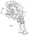
- the roller 17b is arranged on the side of the rocker arm 17c. This asymmetrical design, which can be seen particularly clearly from FIG. 9, results in an extremely space-saving design.
- the roller 17b is also mounted on one Axle that is attached on the one hand to the rocker arm 17c and on the other hand to a further secondary arm 17e. This secondary arm 17e also leads from the rocker arm bearing 17a to the receptacle 17d.
Landscapes
- Engineering & Computer Science (AREA)
- Mechanical Engineering (AREA)
- General Engineering & Computer Science (AREA)
- Valve Device For Special Equipments (AREA)
- Valve-Gear Or Valve Arrangements (AREA)
Applications Claiming Priority (2)
| Application Number | Priority Date | Filing Date | Title |
|---|---|---|---|
| DE4326331 | 1993-08-05 | ||
| DE19934326331 DE4326331A1 (de) | 1992-07-15 | 1993-08-05 | Ventiltrieb einer Brennkraftmaschine |
Publications (1)
| Publication Number | Publication Date |
|---|---|
| EP0638706A1 true EP0638706A1 (fr) | 1995-02-15 |
Family
ID=6494543
Family Applications (1)
| Application Number | Title | Priority Date | Filing Date |
|---|---|---|---|
| EP93119520A Withdrawn EP0638706A1 (fr) | 1993-08-05 | 1993-12-03 | Dispositif de commande d'actionnement des soupapes d'un moteur à combustion interne |
Country Status (3)
| Country | Link |
|---|---|
| US (1) | US5373818A (fr) |
| EP (1) | EP0638706A1 (fr) |
| JP (1) | JP3245492B2 (fr) |
Cited By (17)
| Publication number | Priority date | Publication date | Assignee | Title |
|---|---|---|---|---|
| EP0780547A1 (fr) | 1995-12-22 | 1997-06-25 | Siemens Aktiengesellschaft | Dispositif permettant de varier la loi de leveé d'une soupape de moteur à combustion interne |
| WO1998003778A1 (fr) | 1996-07-20 | 1998-01-29 | Dieter Reitz | Mecanisme de distribution et culasse de moteur a combustion interne |
| WO1999009303A1 (fr) | 1997-08-14 | 1999-02-25 | Siemens Aktiengesellschaft | Procede d'ajustement de la levee d'une soupape |
| DE19810369C1 (de) * | 1998-03-10 | 1999-08-12 | Siemens Ag | Vorrichtung zur Messung des Ventilhubes |
| DE19920512A1 (de) * | 1999-05-05 | 2000-11-09 | Opel Adam Ag | Vorrichtung zur Betätigung eines Ventiles mit variablem Hub an Brennkraftmaschinen |
| US6164254A (en) * | 1997-08-14 | 2000-12-26 | Siemens Aktiengesellschaft | Method for setting valve lift |
| DE19942934A1 (de) * | 1999-09-08 | 2001-03-15 | Siemens Ag | Verfahren zum Messen des maximalen Ventilhubes |
| EP1143118A3 (fr) * | 2000-04-07 | 2002-11-13 | Bayerische Motoren Werke Aktiengesellschaft | Dispositif pour varier la levée d'une soupape dans la culasse d'un moteur à combustion interne |
| WO2004057160A1 (fr) * | 2002-12-21 | 2004-07-08 | Ina-Schaeffler Kg | Levier intermediaire d'un mecanisme de commande variable de soupape d'un moteur a combustion interne |
| DE10251007B4 (de) * | 2001-11-15 | 2007-09-06 | Avl List Gmbh | Mit fremdzündbaren Kraftstoff betriebene Brennkraftmaschine |
| DE102006018512A1 (de) * | 2006-04-21 | 2007-10-25 | Schaeffler Kg | Rollenelement für ein schwenkbewegliches Maschinenteil |
| EP1666714A3 (fr) * | 2004-10-14 | 2010-08-11 | Bayerische Motoren Werke Aktiengesellschaft | Carter pour moteur à combustion |
| DE102010048709A1 (de) | 2010-10-19 | 2012-04-19 | Kolbenschmidt Pierburg Innovations Gmbh | Mechanisch steuerbarer Ventiltrieb sowie mechanisch steuerbare Ventiltriebanordnung |
| WO2012126648A1 (fr) | 2011-03-22 | 2012-09-27 | Kolbenschmidt Pierburg Innovations Gmbh | Entraînement de soupapes à commande mécanique et système d'entraînement de soupapes à commande mécanique |
| DE102013113815A1 (de) | 2013-12-11 | 2015-06-11 | Pierburg Gmbh | Übertragungsanordnung für einen mechanisch steuerbaren Ventiltrieb |
| DE102014114396A1 (de) | 2014-10-02 | 2016-04-07 | Pierburg Gmbh | Mechanisch steuerbarer Ventiltrieb sowie mechanisch steuerbare Ventiltriebanordnung |
| EP3073072A2 (fr) | 2015-03-26 | 2016-09-28 | Pierburg GmbH | Commande de soupape à commande mécanique et système de commande de soupape pouvant être commandé |
Families Citing this family (83)
| Publication number | Priority date | Publication date | Assignee | Title |
|---|---|---|---|---|
| DE19509604A1 (de) * | 1995-03-16 | 1996-09-19 | Bayerische Motoren Werke Ag | Ventiltrieb einer Brennkraftmaschine |
| IT1285853B1 (it) * | 1996-04-24 | 1998-06-24 | Fiat Ricerche | Motore a combustione interna con valvole ad azionamento variabile. |
| AU4815000A (en) * | 1999-05-10 | 2000-11-21 | Armer & Frank Motors, Llc | Valve system having improved opening and breathing characteristics for internal combustion engines |
| JP2001164911A (ja) * | 1999-12-10 | 2001-06-19 | Yamaha Motor Co Ltd | 4サイクルエンジンの動弁機構 |
| DE10016103A1 (de) | 2000-03-31 | 2001-10-04 | Audi Ag | Variable Ventilsteuerung |
| DE10052811A1 (de) * | 2000-10-25 | 2002-05-08 | Ina Schaeffler Kg | Variabler Ventiltrieb zur Laststeuerung einer fremdgezündeten Brennkraftmaschine |
| WO2002081872A1 (fr) | 2001-04-05 | 2002-10-17 | Stephen William Mitchell | Systeme de distribution a programme variable |
| GR20010100295A (el) | 2001-06-18 | 2003-02-27 | Εμμανουηλ Παττακος | Μεταβλητο συστημα βαλβιδων |
| DE10136612A1 (de) * | 2001-07-17 | 2003-02-06 | Herbert Naumann | Variable Hubventilsteuerungen |
| DE10206465A1 (de) * | 2002-02-16 | 2003-08-28 | Mahle Ventiltrieb Gmbh | Steuereinrichtung für Gaswechselventile eines Verbrennungsmotors |
| DE10211999A1 (de) * | 2002-03-18 | 2003-10-02 | Ina Schaeffler Kg | Verfahren und Vorrichtung zum Steuern der Zylinderladung eines fremdgezündeten Verbrennungsmotors |
| AU2003242323A1 (en) * | 2002-05-17 | 2003-12-02 | Koichi Hatamura | Engine valve driver |
| WO2003098013A1 (fr) | 2002-05-17 | 2003-11-27 | Yamaha Hatsudoki Kabushiki Kaisha | Dispositif d'entrainement de soupape de moteur |
| US6659053B1 (en) | 2002-06-07 | 2003-12-09 | Eaton Corporation | Fully variable valve train |
| DE10228022B4 (de) * | 2002-06-20 | 2009-04-23 | Entec Consulting Gmbh | Ventilhubvorrichtung zur Hubverstellung der Gaswechselventile einer Verbrennungskraftmaschine |
| DE10261304B4 (de) * | 2002-12-27 | 2009-01-22 | BÖSL-FLIERL, Gerlinde | Ventilhubvorrichtung zur variablen Ventilsteuerung der Gaswechselventile einer Verbrennungskraftmaschine |
| US7107949B2 (en) * | 2003-02-19 | 2006-09-19 | Iav Gmbh Ingenieurgesellschaft Auto Und Verkeh | Device for variable activation of valves for internal combustion engines |
| CA2518949A1 (fr) | 2003-03-11 | 2004-09-23 | Yamaha Hatsudoki Kabushiki Kaisha | Mecanisme de soupape variable pour moteur a combustion interne |
| US7007649B2 (en) * | 2003-03-18 | 2006-03-07 | General Motors Corporation | Engine valve actuator assembly |
| US6688267B1 (en) | 2003-03-19 | 2004-02-10 | General Motors Corporation | Engine valve actuator assembly |
| DE10314683B4 (de) * | 2003-03-29 | 2009-05-07 | Entec Consulting Gmbh | Variable Ventilhubsteuerung für einen Verbrennungsmotor mit untenliegender Nockenwelle |
| EP1618293B1 (fr) * | 2003-03-29 | 2008-09-24 | Hydraulik-Ring Gmbh | Dispositif de poussoir a soupape variable utilise pour ajuster les soupapes d'echange de gaz dans un moteur a combustion interne |
| US6883474B2 (en) * | 2003-04-02 | 2005-04-26 | General Motors Corporation | Electrohydraulic engine valve actuator assembly |
| US6837196B2 (en) * | 2003-04-02 | 2005-01-04 | General Motors Corporation | Engine valve actuator assembly with automatic regulation |
| US6918360B2 (en) * | 2003-04-02 | 2005-07-19 | General Motors Corporation | Engine valve actuator assembly with hydraulic feedback |
| US6886510B2 (en) | 2003-04-02 | 2005-05-03 | General Motors Corporation | Engine valve actuator assembly with dual hydraulic feedback |
| JP4248343B2 (ja) | 2003-05-01 | 2009-04-02 | ヤマハ発動機株式会社 | エンジンの動弁装置 |
| JP4248344B2 (ja) * | 2003-05-01 | 2009-04-02 | ヤマハ発動機株式会社 | エンジンの動弁装置 |
| AU2004265498A1 (en) * | 2003-08-18 | 2005-02-24 | Emmanouel Pattakos | Variable valve gear |
| JP4247529B2 (ja) * | 2003-08-22 | 2009-04-02 | ヤマハ発動機株式会社 | 内燃機関の動弁機構 |
| JP2005069014A (ja) * | 2003-08-25 | 2005-03-17 | Yamaha Motor Co Ltd | 内燃機関の動弁機構 |
| JP4237643B2 (ja) | 2003-08-25 | 2009-03-11 | ヤマハ発動機株式会社 | 内燃機関の動弁機構 |
| JP4039383B2 (ja) * | 2003-10-21 | 2008-01-30 | トヨタ自動車株式会社 | 水素利用内燃機関 |
| US6945204B2 (en) * | 2003-11-12 | 2005-09-20 | General Motors Corporation | Engine valve actuator assembly |
| DE602004006649T2 (de) * | 2003-12-18 | 2008-01-31 | Toyota Jidosha Kabushiki Kaisha, Toyota | Variabler ventilmechanismus |
| JP4225321B2 (ja) | 2003-12-18 | 2009-02-18 | トヨタ自動車株式会社 | 可変動弁機構 |
| RU2330164C2 (ru) * | 2004-01-16 | 2008-07-27 | Хонда Мотор Ко., Лтд. | Система привода клапанов двигателя |
| JP4238203B2 (ja) * | 2004-01-30 | 2009-03-18 | 本田技研工業株式会社 | エンジン |
| JP4381188B2 (ja) * | 2004-03-19 | 2009-12-09 | 三菱ふそうトラック・バス株式会社 | 内燃機関の可変動弁装置 |
| WO2005090758A1 (fr) | 2004-03-23 | 2005-09-29 | Mitsubishi Fuso Truck And Bus Corporation | Commande de soupapes variable de moteur a combustion interne |
| JP4221327B2 (ja) * | 2004-04-13 | 2009-02-12 | 三菱ふそうトラック・バス株式会社 | 内燃機関の可変動弁装置 |
| KR100621961B1 (ko) | 2004-04-13 | 2006-09-19 | 미쯔비시 지도샤 고교 가부시끼가이샤 | 내연 기관의 가변식 구동 밸브 장치 |
| JP4327645B2 (ja) * | 2004-04-13 | 2009-09-09 | 三菱ふそうトラック・バス株式会社 | V型エンジンの可変動弁装置 |
| JP4343021B2 (ja) | 2004-04-28 | 2009-10-14 | 本田技研工業株式会社 | 内燃機関の動弁装置 |
| JP4342372B2 (ja) | 2004-04-28 | 2009-10-14 | 本田技研工業株式会社 | 内燃機関の動弁装置 |
| JP4412190B2 (ja) | 2004-04-28 | 2010-02-10 | トヨタ自動車株式会社 | 可変動弁機構 |
| JP4103872B2 (ja) | 2004-08-31 | 2008-06-18 | トヨタ自動車株式会社 | 可変動弁装置 |
| EP1785598B1 (fr) | 2004-08-31 | 2010-12-15 | Toyota Jidosha Kabushiki Kaisha | Commande de soupapes variable |
| JP4278590B2 (ja) | 2004-08-31 | 2009-06-17 | 株式会社日立製作所 | 内燃機関の可変動弁装置 |
| JP4103871B2 (ja) | 2004-08-31 | 2008-06-18 | トヨタ自動車株式会社 | 可変動弁装置 |
| JP4026634B2 (ja) | 2004-08-31 | 2007-12-26 | トヨタ自動車株式会社 | 可変動弁装置 |
| US6932035B1 (en) * | 2005-01-28 | 2005-08-23 | Ford Global Technologies, Llc | Cylinder valve operating system for internal combustion engine |
| JP2006307765A (ja) | 2005-04-28 | 2006-11-09 | Honda Motor Co Ltd | 内燃機関のリフト可変動弁装置 |
| JP2006329084A (ja) | 2005-05-26 | 2006-12-07 | Yamaha Motor Co Ltd | エンジンの動弁装置 |
| JP2006329164A (ja) | 2005-05-30 | 2006-12-07 | Yamaha Motor Co Ltd | 複数気筒エンジン |
| JP4507997B2 (ja) * | 2005-06-15 | 2010-07-21 | 三菱自動車工業株式会社 | 内燃機関の可変動弁装置 |
| JP4546427B2 (ja) * | 2006-07-19 | 2010-09-15 | 本田技研工業株式会社 | 内燃機関の可変動弁機構 |
| DE102005040959A1 (de) * | 2005-08-30 | 2007-03-08 | Bayerische Motoren Werke Ag | Hubvariabler Ventiltrieb für eine Brennkraftmaschine |
| JP2007077940A (ja) * | 2005-09-15 | 2007-03-29 | Otics Corp | 可変動弁機構 |
| JP2007127117A (ja) * | 2005-10-04 | 2007-05-24 | Masaaki Yoshikawa | 4ストローク内燃機関の動弁系装置 |
| JP4518010B2 (ja) * | 2005-12-01 | 2010-08-04 | 三菱自動車工業株式会社 | 内燃機関の可変動弁装置 |
| JP2007198363A (ja) * | 2005-12-26 | 2007-08-09 | Otics Corp | 可変動弁機構 |
| US7162983B1 (en) | 2006-02-22 | 2007-01-16 | Gm Global Technology Operations, Inc. | Valve actuator assembly for variable displacement of an engine valve |
| JP4697011B2 (ja) * | 2006-04-03 | 2011-06-08 | トヨタ自動車株式会社 | 可変動弁機構 |
| JP4519104B2 (ja) * | 2006-06-01 | 2010-08-04 | 日立オートモティブシステムズ株式会社 | 内燃機関の可変動弁装置 |
| JP4726775B2 (ja) | 2006-12-20 | 2011-07-20 | ヤマハ発動機株式会社 | エンジンの連続可変式動弁装置 |
| US7404386B1 (en) | 2007-02-13 | 2008-07-29 | Gm Global Technology Operations, Inc. | Multi-step valve actuation system |
| JP4440293B2 (ja) | 2007-10-05 | 2010-03-24 | 本田技研工業株式会社 | 開弁特性可変型内燃機関 |
| JP2009091943A (ja) * | 2007-10-05 | 2009-04-30 | Honda Motor Co Ltd | 開弁特性可変型内燃機関 |
| JP5137595B2 (ja) * | 2008-01-18 | 2013-02-06 | ダイハツ工業株式会社 | 内燃機関のバルブリフト可変式動弁装置 |
| KR100986355B1 (ko) * | 2008-07-23 | 2010-10-08 | 현대자동차주식회사 | 슬라이드형 연속 가변 밸브 리프트 장치 |
| EP2157292A1 (fr) | 2008-08-20 | 2010-02-24 | Delphi Technologies, Inc. | Ensemble de soupape d'échappement pour moteur à combustion interne |
| US8602002B2 (en) | 2010-08-05 | 2013-12-10 | GM Global Technology Operations LLC | System and method for controlling engine knock using electro-hydraulic valve actuation |
| DE102010048708A1 (de) * | 2010-10-19 | 2012-04-19 | Kolbenschmidt Pierburg Innovations Gmbh | Mechanisch steuerbarer Ventiltrieb |
| US8839750B2 (en) | 2010-10-22 | 2014-09-23 | GM Global Technology Operations LLC | System and method for controlling hydraulic pressure in electro-hydraulic valve actuation systems |
| US8781713B2 (en) | 2011-09-23 | 2014-07-15 | GM Global Technology Operations LLC | System and method for controlling a valve of a cylinder in an engine based on fuel delivery to the cylinder |
| US9169787B2 (en) | 2012-05-22 | 2015-10-27 | GM Global Technology Operations LLC | Valve control systems and methods for cylinder deactivation and activation transitions |
| US9567928B2 (en) | 2012-08-07 | 2017-02-14 | GM Global Technology Operations LLC | System and method for controlling a variable valve actuation system to reduce delay associated with reactivating a cylinder |
| CN103244230B (zh) * | 2013-05-23 | 2015-07-01 | 长城汽车股份有限公司 | 车辆、发动机及其可变气门升程装置 |
| EP3296531A1 (fr) * | 2016-09-14 | 2018-03-21 | Mechadyne International Limited | Système de soupape de moteur |
| CN108561231B (zh) * | 2017-06-09 | 2020-09-04 | 长城汽车股份有限公司 | 连续可变气门升程机构的控制策略 |
| JP2020033872A (ja) * | 2018-08-27 | 2020-03-05 | 株式会社オティックス | 内燃機関の可変動弁機構 |
| CN112282959A (zh) * | 2020-10-28 | 2021-01-29 | 哈尔滨工程大学 | 一种二冲程船用低速机四排气阀结构 |
Citations (7)
| Publication number | Priority date | Publication date | Assignee | Title |
|---|---|---|---|---|
| FR2506834A1 (fr) * | 1981-05-27 | 1982-12-03 | Honda Motor Co Ltd | Dispositif de calage variable de soupape d'un moteur a combustion interne |
| WO1983002301A1 (fr) * | 1981-12-31 | 1983-07-07 | BAGUÉNA, Michel | Distribution variable pour moteur a quatre temps |
| DE3621080A1 (de) * | 1985-06-24 | 1987-01-02 | Nissan Motor | Ventilzeitsteuerungsvorrichtung fuer verbrennungsmotoren mit mehreren einlassventilen pro zylinder |
| DE3730001A1 (de) * | 1987-09-08 | 1989-03-30 | Gerhard Werner Kappelmeier | Ventilbetaetigungsmechanismus fuer eine verbrennungskraftmaschine |
| EP0319956A1 (fr) * | 1987-12-08 | 1989-06-14 | Nissan Motor Co., Ltd. | Dispositif de commande de soupape |
| EP0462853A1 (fr) * | 1990-06-21 | 1991-12-27 | Automobiles Peugeot | Dispositif à amplitude variable pour la levée d'au moins une soupape de moteur à combustion interne |
| US5189998A (en) * | 1991-07-23 | 1993-03-02 | Atsugi Unisia Corporation | Valve mechanism of internal combustion engine |
Family Cites Families (8)
| Publication number | Priority date | Publication date | Assignee | Title |
|---|---|---|---|---|
| US3413965A (en) * | 1967-07-13 | 1968-12-03 | Ford Motor Co | Mechanism for varying the operation of a reciprocating member |
| US4138973A (en) * | 1974-06-14 | 1979-02-13 | David Luria | Piston-type internal combustion engine |
| US4526142A (en) * | 1981-06-24 | 1985-07-02 | Nissan Motor Company, Limited | Variable valve timing arrangement for an internal combustion engine or the like |
| JPH036801Y2 (fr) * | 1986-11-18 | 1991-02-20 | ||
| DE3833540A1 (de) * | 1988-10-01 | 1990-04-12 | Peter Prof Dr Ing Kuhn | Vorrichtung zur betaetigung der ventile an verbrennungsmotoren mit veraenderlicher ventilerhebungskurve |
| JP2700692B2 (ja) * | 1989-06-30 | 1998-01-21 | スズキ株式会社 | 4サイクルエンジンの動弁装置 |
| EP0452671B1 (fr) * | 1990-03-14 | 1995-06-14 | Suzuki Kabushiki Kaisha | Dispositif de commande de soupape pour moteur à quatre temps |
| US5025761A (en) * | 1990-06-13 | 1991-06-25 | Chen Kuang Tong | Variable valve-timing device |
-
1993
- 1993-12-03 EP EP93119520A patent/EP0638706A1/fr not_active Withdrawn
- 1993-12-24 JP JP32807293A patent/JP3245492B2/ja not_active Expired - Fee Related
- 1993-12-30 US US08/176,280 patent/US5373818A/en not_active Expired - Lifetime
Patent Citations (7)
| Publication number | Priority date | Publication date | Assignee | Title |
|---|---|---|---|---|
| FR2506834A1 (fr) * | 1981-05-27 | 1982-12-03 | Honda Motor Co Ltd | Dispositif de calage variable de soupape d'un moteur a combustion interne |
| WO1983002301A1 (fr) * | 1981-12-31 | 1983-07-07 | BAGUÉNA, Michel | Distribution variable pour moteur a quatre temps |
| DE3621080A1 (de) * | 1985-06-24 | 1987-01-02 | Nissan Motor | Ventilzeitsteuerungsvorrichtung fuer verbrennungsmotoren mit mehreren einlassventilen pro zylinder |
| DE3730001A1 (de) * | 1987-09-08 | 1989-03-30 | Gerhard Werner Kappelmeier | Ventilbetaetigungsmechanismus fuer eine verbrennungskraftmaschine |
| EP0319956A1 (fr) * | 1987-12-08 | 1989-06-14 | Nissan Motor Co., Ltd. | Dispositif de commande de soupape |
| EP0462853A1 (fr) * | 1990-06-21 | 1991-12-27 | Automobiles Peugeot | Dispositif à amplitude variable pour la levée d'au moins une soupape de moteur à combustion interne |
| US5189998A (en) * | 1991-07-23 | 1993-03-02 | Atsugi Unisia Corporation | Valve mechanism of internal combustion engine |
Cited By (29)
| Publication number | Priority date | Publication date | Assignee | Title |
|---|---|---|---|---|
| EP0780547A1 (fr) | 1995-12-22 | 1997-06-25 | Siemens Aktiengesellschaft | Dispositif permettant de varier la loi de leveé d'une soupape de moteur à combustion interne |
| DE19548389A1 (de) * | 1995-12-22 | 1997-06-26 | Siemens Ag | Verstellvorrichtung für den Hubverlauf eines Gaswechselventils einer Brennkraftmaschine |
| WO1998003778A1 (fr) | 1996-07-20 | 1998-01-29 | Dieter Reitz | Mecanisme de distribution et culasse de moteur a combustion interne |
| US6164254A (en) * | 1997-08-14 | 2000-12-26 | Siemens Aktiengesellschaft | Method for setting valve lift |
| WO1999009303A1 (fr) | 1997-08-14 | 1999-02-25 | Siemens Aktiengesellschaft | Procede d'ajustement de la levee d'une soupape |
| DE19810369C1 (de) * | 1998-03-10 | 1999-08-12 | Siemens Ag | Vorrichtung zur Messung des Ventilhubes |
| DE19920512A1 (de) * | 1999-05-05 | 2000-11-09 | Opel Adam Ag | Vorrichtung zur Betätigung eines Ventiles mit variablem Hub an Brennkraftmaschinen |
| DE19942934A1 (de) * | 1999-09-08 | 2001-03-15 | Siemens Ag | Verfahren zum Messen des maximalen Ventilhubes |
| DE19942934B4 (de) * | 1999-09-08 | 2005-08-04 | Siemens Ag | Verfahren zum Verwenden des Wertes des maximalen Ventilhubes eines Gaswechselventils |
| EP1143118A3 (fr) * | 2000-04-07 | 2002-11-13 | Bayerische Motoren Werke Aktiengesellschaft | Dispositif pour varier la levée d'une soupape dans la culasse d'un moteur à combustion interne |
| DE10251007B4 (de) * | 2001-11-15 | 2007-09-06 | Avl List Gmbh | Mit fremdzündbaren Kraftstoff betriebene Brennkraftmaschine |
| WO2004057160A1 (fr) * | 2002-12-21 | 2004-07-08 | Ina-Schaeffler Kg | Levier intermediaire d'un mecanisme de commande variable de soupape d'un moteur a combustion interne |
| US7055478B2 (en) | 2002-12-21 | 2006-06-06 | Ina-Schaeffler Kg | Intermediate lever for a variable valve train of an internal combustion engine |
| EP1666714A3 (fr) * | 2004-10-14 | 2010-08-11 | Bayerische Motoren Werke Aktiengesellschaft | Carter pour moteur à combustion |
| DE102006018512A1 (de) * | 2006-04-21 | 2007-10-25 | Schaeffler Kg | Rollenelement für ein schwenkbewegliches Maschinenteil |
| DE102010048709B4 (de) * | 2010-10-19 | 2013-01-03 | Kolbenschmidt Pierburg Innovations Gmbh | Mechanisch steuerbarer Ventiltrieb sowie mechanisch steuerbare Ventiltriebanordnung |
| DE102010048709A1 (de) | 2010-10-19 | 2012-04-19 | Kolbenschmidt Pierburg Innovations Gmbh | Mechanisch steuerbarer Ventiltrieb sowie mechanisch steuerbare Ventiltriebanordnung |
| WO2012052216A1 (fr) | 2010-10-19 | 2012-04-26 | Kolbenschmidt Pierburg Innovations Gmbh | Distribution à commande mécanique et ensemble de distribution à commande mécanique |
| US8807104B2 (en) | 2010-10-19 | 2014-08-19 | Kolbenschmidt Pierburg Innovations Gmbh | Mechanically controllable valve operating mechanism, and mechanically controllable valve operating mechanism arrangement |
| WO2012126648A1 (fr) | 2011-03-22 | 2012-09-27 | Kolbenschmidt Pierburg Innovations Gmbh | Entraînement de soupapes à commande mécanique et système d'entraînement de soupapes à commande mécanique |
| DE102011014744A1 (de) | 2011-03-22 | 2012-09-27 | Kolbenschmidt Pierburg Innovations Gmbh | Mechanisch steuerbarer Ventiltrieb sowie mechanisch steuerbare Ventiltriebanordnung |
| US9133737B2 (en) | 2011-03-22 | 2015-09-15 | Kolbenschmidt Pierburg Innovations Gmbh | Mechanically controllable valve drive and mechanically controllable valve drive arrangement |
| DE102013113815A1 (de) | 2013-12-11 | 2015-06-11 | Pierburg Gmbh | Übertragungsanordnung für einen mechanisch steuerbaren Ventiltrieb |
| EP2905437A2 (fr) | 2013-12-11 | 2015-08-12 | Pierburg GmbH | Système de transmission pour une commande de soupape pouvant être commandée mécaniquement |
| US9464540B2 (en) | 2013-12-11 | 2016-10-11 | Pierburg Gmbh | Transfer assembly for a mechanically controllable valve train |
| DE102014114396A1 (de) | 2014-10-02 | 2016-04-07 | Pierburg Gmbh | Mechanisch steuerbarer Ventiltrieb sowie mechanisch steuerbare Ventiltriebanordnung |
| EP3006684A1 (fr) | 2014-10-02 | 2016-04-13 | Pierburg GmbH | Commande de soupape a commande mecanique et systeme de commande de soupape pouvant etre commande |
| EP3073072A2 (fr) | 2015-03-26 | 2016-09-28 | Pierburg GmbH | Commande de soupape à commande mécanique et système de commande de soupape pouvant être commandé |
| DE102015104633A1 (de) | 2015-03-26 | 2016-09-29 | Pierburg Gmbh | Mechanisch steuerbarer Ventiltrieb sowie mechanisch steuerbare Ventiltriebanordnung |
Also Published As
| Publication number | Publication date |
|---|---|
| JP3245492B2 (ja) | 2002-01-15 |
| JPH0763023A (ja) | 1995-03-07 |
| US5373818A (en) | 1994-12-20 |
Similar Documents
| Publication | Publication Date | Title |
|---|---|---|
| EP0638706A1 (fr) | Dispositif de commande d'actionnement des soupapes d'un moteur à combustion interne | |
| DE102017101792B4 (de) | Variabler Ventiltrieb eines Verbrennungskolbenmotors | |
| AT408127B (de) | Brennkraftmaschine mit mindestens einer durch eine verstellvorrichtung axial verschiebbaren nockenwelle | |
| DE60304621T2 (de) | Kipphebel zur zweistufigen Nockenbetätigung | |
| DE102011052912A1 (de) | Brennkraftmaschine und Ventiltrieb für eine Brennkraftmaschine | |
| DE102008028513A1 (de) | Ventilbetrieb für Gaswechselventile einer Brennkraftmaschine mit doppelt abgestützten Nockenträgern | |
| DE4326331A1 (de) | Ventiltrieb einer Brennkraftmaschine | |
| EP0712462B1 (fr) | Ensemble culbuteur a bras reliables | |
| DE19509604A1 (de) | Ventiltrieb einer Brennkraftmaschine | |
| WO2019007453A1 (fr) | Commande de soupape variable d'un moteur à combustion interne à piston | |
| DE102016212480A1 (de) | Variabler Ventiltrieb eines Verbrennungskolbenmotors | |
| DE4223173A1 (de) | Ventiltrieb einer Brennkraftmaschine | |
| DE102012012150B4 (de) | Schlepphebelanordnung und Verbrennungsmotor | |
| EP1205643A1 (fr) | Dispositif d'actionnement de soupapes de moteur à combustion interne | |
| EP3173593B1 (fr) | Commande de soupape variable comprenant un culbuteur | |
| DE102017129424A1 (de) | Variabler Ventiltrieb eines Verbrennungskolbenmotors | |
| EP0352580B1 (fr) | Dispositif d'actionnement de soupapes d'un moteur à combustion interne | |
| DE102004008389A1 (de) | Hubvariabler Ventiltrieb für eine Brennkraftmaschine | |
| DE4124305C2 (de) | Ventiltrieb für eine Brennkraftmaschine | |
| DE102005010182B4 (de) | Variabel mechanische Ventilsteuerung einer Brennkraftmaschine | |
| DE10312959A1 (de) | Vorrichtung zur variablen Betätigung der Gaswechselventile von Verbrennungsmotoren und Verfahren zum Betreiben einer derartigen Vorrichtung | |
| DE102018128796A1 (de) | Variabler Ventiltrieb einer Brennkraftmaschine | |
| DE102016222046A1 (de) | Ventiltrieb für eine Brennkraftmaschine | |
| EP1608852A1 (fr) | Dispositif d'actionnement variable des soupapes d'echange des gaz de moteurs a combustion interne et procede permettant de faire fonctionner un dispositif de ce type | |
| EP3073072A2 (fr) | Commande de soupape à commande mécanique et système de commande de soupape pouvant être commandé |
Legal Events
| Date | Code | Title | Description |
|---|---|---|---|
| PUAI | Public reference made under article 153(3) epc to a published international application that has entered the european phase |
Free format text: ORIGINAL CODE: 0009012 |
|
| AK | Designated contracting states |
Kind code of ref document: A1 Designated state(s): ES FR GB IT SE |
|
| STAA | Information on the status of an ep patent application or granted ep patent |
Free format text: STATUS: THE APPLICATION IS DEEMED TO BE WITHDRAWN |
|
| 18D | Application deemed to be withdrawn |
Effective date: 19950816 |