EP0638885A1 - Appareil de détection d'incendie - Google Patents
Appareil de détection d'incendie Download PDFInfo
- Publication number
- EP0638885A1 EP0638885A1 EP94111614A EP94111614A EP0638885A1 EP 0638885 A1 EP0638885 A1 EP 0638885A1 EP 94111614 A EP94111614 A EP 94111614A EP 94111614 A EP94111614 A EP 94111614A EP 0638885 A1 EP0638885 A1 EP 0638885A1
- Authority
- EP
- European Patent Office
- Prior art keywords
- dust
- fire detecting
- recovering
- air
- fire
- Prior art date
- Legal status (The legal status is an assumption and is not a legal conclusion. Google has not performed a legal analysis and makes no representation as to the accuracy of the status listed.)
- Granted
Links
Images


Classifications
-
- B—PERFORMING OPERATIONS; TRANSPORTING
- B01—PHYSICAL OR CHEMICAL PROCESSES OR APPARATUS IN GENERAL
- B01D—SEPARATION
- B01D45/00—Separating dispersed particles from gases or vapours by gravity, inertia, or centrifugal forces
- B01D45/04—Separating dispersed particles from gases or vapours by gravity, inertia, or centrifugal forces by utilising inertia
- B01D45/06—Separating dispersed particles from gases or vapours by gravity, inertia, or centrifugal forces by utilising inertia by reversal of direction of flow
-
- B—PERFORMING OPERATIONS; TRANSPORTING
- B01—PHYSICAL OR CHEMICAL PROCESSES OR APPARATUS IN GENERAL
- B01D—SEPARATION
- B01D50/00—Combinations of methods or devices for separating particles from gases or vapours
- B01D50/20—Combinations of devices covered by groups B01D45/00 and B01D46/00
-
- G—PHYSICS
- G08—SIGNALLING
- G08B—SIGNALLING SYSTEMS, e.g. PERSONAL CALLING SYSTEMS; ORDER TELEGRAPHS; ALARM SYSTEMS
- G08B17/00—Fire alarms; Alarms responsive to explosion
- G08B17/10—Actuation by presence of smoke or gases, e.g. automatic alarm devices for analysing flowing fluid materials by the use of optical means
- G08B17/117—Actuation by presence of smoke or gases, e.g. automatic alarm devices for analysing flowing fluid materials by the use of optical means by using a detection device for specific gases, e.g. combustion products, produced by the fire
Definitions
- the present invention relates to a fire detecting apparatus comprising a fire detecting part for detecting the presence of a fire by detecting smoke in the air introduced from a supervision area into the fire detecting part through an inlet passage within which dust protection means are arranged.
- a fire detecting part of the fire detecting apparatus of this type such as ionization type, light scattering type, or light obscuration type.
- a fire detecting part detects smoke in the air introduced from a supervision area so as to detect the presence of a fire according to the density of the smoke.
- Fig. 6 is a schematic view of the construction of one example of a conventional fire detecting apparatus of light scattering type (photoelectric type).
- an air inlet 2 is arranged to face a supervision area 1 and a filter 3 is provided for the air inlet 2.
- a detecting part case 4 is connected to the air inlet 2.
- a light-emitting device 5 is mounted on an inner wall of the detecting part case 4.
- a light-receiving device 7 is mounted on a preamplifier 6 arranged within the detecting part case 4.
- a plurality of light-screening plates 8 protrude from the inner walls of the detecting part case 4.
- the fire detecting part 9 comprises the above-noted detecting part case 4, the light-emitting device 5, the preamplifier 6, the light-receiving device 7 and the light-screening plates 8.
- a suction fan 10 is connected to the outside of the detecting part case 4.
- a fire determining part 11 is electrically connected to the preamplifier 6.
- the suction fan 10 is driven so as to allow the air in the supervision area 1 to be introduced into the detecting part case 4 from the air inlet 2 through the filter 3 and to be discharged from the suction fan 10.
- the light-emitting device 5 emits light, which is normally screened by the light-screening plates 8, thereby preventing the light from being received by the light-receiving device 7.
- the conventional fire detecting apparatus constructed as described above presents the following problems.
- the dust floating in the supervision area 1, together with the air is introduced into the fire detecting part 9, it scatters the light emitted from the light-emitting device 5 as smoke does.
- the fire determining part 11 determines the presence of a fire due to the dust, thus resulting in an erroneous operation.
- fire detecting apparatuses used in clean rooms and computer rooms determine the presence of a fire with a considerably lower density of smoke, as stated above, they are significantly influenced by dust. Further, in the apparatus shown in Fig.
- the filter 3 is provided for the air inlet 2 in order to decrease dust which will flow into the fire detecting part 9.
- it is necessary to some degree to form a filter with small meshes, and accordingly, the filter is likely to be clogged with relatively large dust particles, waste, and the like.
- an object of the present invention is to provide a fire detecting apparatus which is able to more reliably avoid erroneous operations caused by dust in the air and to improve reliability.
- a fire detecting apparatus comprising: a fire detecting part for detecting the presence of a fire by detecting smoke in the air introduced from a supervision area; a first dust recovering part arranged at a midpoint in an inlet passage of the air into the fire detecting part so as to deflect the air flow, thereby causing dust to drop to separate from the air flow and to be recovered by the recovering part; and a second dust recovering part arranged downstream from the first dust recovering part in the inlet passage and having a filter for recovering dust in the air which has passed through the first dust recovering part.
- a fire detecting apparatus comprising: a fire detecting part for detecting the presence of a fire by detecting smoke in the air introduced from a supervision area; and a dust recovering part arranged at a midpoint in an inlet passage of the air into the fire detecting part and having a plurality of filters placed from upstream in the order from larger to smaller meshes so as to recover dust in the air.
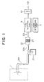
- Fig. 1 is a schematic view of the construction of a fire detecting apparatus according to a first embodiment of the present invention.
- a first dust recovering part 21 is connected to a supervision area 1 via piping 20a.
- the first dust recovering part 21 is adapted to deflect the air flow in a U-shape form therein so as to cause the dust to drop to separate from the air flow and then to be recovered by the recovering part 21.
- a second dust recovering part 22 is connected downstream of the first dust recovering part 21 via piping 20b.
- the second dust recovering part 22 has a filter 23 for recovering the dust in the air which has passed through the first dust recovering part 21.
- the filter 23 is formed of a porous material, such as sponge, or the like.
- a fire detecting part 9 of light scattering type, light obscuration type, ionization type, or the like, and a suction fan 10 are connected downstream of the second dust recovering part 22 via piping 20c.
- a fire determining part 11 is electrically connected to the fire detecting part 9.
- the suction fan 10 is driven so as to allow the air within the supervision area 1 to be introduced into the first dust recovering part 21 through the piping 20a.
- the air flow is deflected in a U-shape form in the first dust recovering part 21 so as to cause waste, such as relatively large and heavy dust particles, insects, or the like, to drop to separate from the air flow and then to be recovered by the recovering part 21.
- waste such as relatively large and heavy dust particles, insects, or the like
- Such first and second dust recovering parts 21 and 22 remove the dust in the air before it is introduced into the fire detecting part 9.
- the fire detecting part 9 is not influenced by the dust which would be brought from the supervision area 1, and accordingly, it is able to detect smoke density with higher precision, thus preventing erroneous operations and improving its reliability as a fire detecting apparatus.
- the filter 3 is used in the foregoing conventional apparatus, it is likely to be clogged with relatively large waste particles, or the like.
- the air flow passes through the filter 23, which is therefore unlikely to be clogged even though it is to some extent made with small meshes.
- the single filter 23 may be modified to be a plurality of filters placed from upstream in the order from larger to smaller meshes.
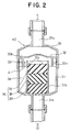
- Fig. 2 is a partially sectional view of a fire detecting apparatus according to a second embodiment of the present invention.
- an air outlet 31a is arranged at the bottom of a case 31.
- a cylindrical portion 31b extending upward from the air outlet 31a is formed in the case 31.
- a partitioning plate 32 is bonded onto the case 31 via packing 33.
- the partitioning plate 32 is provided with a ring-like wall 32 protruding downward to surround one end of the cylindrical portion 31b.
- a plurality of ventilating openings 32b are arranged outside the ring-like wall 32a of the partitioning plate 32.
- a first dust recovering part 34 is formed outside the cylindrical portion 31b within the case 31 and the partitioning plate 32.
- the air flow is deflected in a U-shape form indicated by the arrow A in Fig. 2 on the first dust recovering part 34 so as to cause the dust to drop to separate from the air flow to the outside of the cylindrical portion 31b in the case 31 and then to be recovered by the recovering part 34.
- a cover 35 is screwed to the top ends of the case 31 and the partitioning plate 32.
- An air inlet 35a is further formed on the top end of the cover 35.
- a second dust recovering part 36 is arranged in the cylindrical portion 31b. It comprises first, second and third filters 37, 38 and 39 stacked with each other from upstream in the order of larger to smaller meshes, such filters 37, 38 and 39 being formed of a porous material, such as sponge, or the like. Also, a plurality of projections 31c for holding the second dust recovering part 36 are arranged on an inner wall of the cylindrical portion 31b.
- a dust recovering unit generally denoted by 40 comprises the case 31, the partitioning plate 32, the packing 33, the cover 35 and the second dust recovering part 36. Such a unit 40 is detachably placed between the supervision area 1 and the fire detecting part 9, which are similar to those shown in Fig. 1.
- the air which has had dust removed after passing through the first and second dust recovering parts 34 and 36 is fed into the fire detecting part 9 in which the smoke density can be detected with higher precision, such detection not being influenced by dust in the air which would be brought from the supervision area 1.
- the fire detecting part 9 in which the smoke density can be detected with higher precision, such detection not being influenced by dust in the air which would be brought from the supervision area 1.
- the second dust recovering part 36 is formed of three-stage filters 37, 38 and 39, thereby preventing the filters 37, 38 and 39 from being clogged.
- the filter 39 with finer meshes than those of conventional filters can be placed farthest downstream so that it can recover smaller dust particles, thereby more reliably avoiding erroneous operations caused by dust.
- the first and second dust recovering parts 34 and 36 are integrated to form the dust recovering unit 40, which is detachable from the air inlet passage, thereby permitting easy removing of the recovered dust particles by detaching and dissembling it and the easy replacement of the filters 37 - 39.
- Fig. 3 is a partially sectional view of a fire detecting apparatus according to a third embodiment of the present invention.
- the ring-like wall 32a is removed from the partitioning plate 32 illustrated in Fig. 2.
- the first dust recovering part 34 can be constructed such that the air flow is deflected as indicated by the arrow B, and accordingly, advantages similar to those in the above second embodiment can be obtained.
- the first dust recovering part 34 may be modified in any form as long as it is constructed to deflect the air flow so as to cause heavy dust particles, waste, and the like, to drop to separate from such flow, in which case, the deflecting angle is not particularly restricted.
- Fig. 4 is a partially sectional view of a fire detecting apparatus according to a fourth embodiment of the present invention.
- a dark chamber 42 is formed as a smoke detection space in a cylindrical or rectangular-column casing 41.
- Fixed to the outside of the casing 41 are a light-emitting device 43 which emits light to the dark chamber 42, such as a light-emitting diode, and a light-receiving device 43 which receives light from the dark chamber 42, such as a solar cell and a photo diode.
- a lens 44 is arranged in front of the light-emitting device 43 to transform the light from the light-emitting device 43 into the circular-cylindrical light beam.
- Another lens 46 is arranged in front of the light-receiving device 45 to form a light-receiving range of the light-receiving device 45 in a circular-cylindrical shape.
- An intermediate plate 47 is provided for the casing 41 to partition the dark chamber 42 and also to be used as a filter holder.
- the intermediate plate 47 is provided with a plurality of ventilation holes (smoke inlet openings) 47a which are placed in, for example, a ring-like shape.
- a filter accommodating chamber 48 used as a unit case is inserted into any portion in the casing 41 other than the dark chamber 42 so as to serve the function of a lid plate for one end of the casing 41.
- a plurality of ventilation openings 48a are provided for the outer periphery of one end of the filter accommodating chamber 48.
- the first to fourth filters 49 - 52 formed of a porous material, such as sponge, or the like, are accommodated within the filter accommodating chamber 48. Such filters 49 - 52 are stacked from upstream (on the left-hand side of Fig. 4) in the order from larger to smaller meshes.
- a dust recovering part 53 comprises the first to fourth filters 49 - 52.
- An air inlet 54 for introducing the air into the casing 41 from the supervision area 1, which is similar to that shown in Fig. 1, is attached at the outer periphery of one end to the casing 41, facing the ventilation openings 48a.
- An air outlet 55 is attached at the other end to the casing 41 so as also to be used as a lid for its other end.
- a suction fan 10 is connected downstream of the air outlet 55 in a manner similar to the first embodiment shown in Fig. 1.
- the fire detecting part 9 of the fourth embodiment comprises the dark chamber 42, the light-emitting device 43, the lens 44, the light-receiving device 45 and the other lens 46, and the like.
- the light-emitting device 43 is controlled by a light-emitting control circuit (not shown) to emit pulse light intermittently (for example, every three seconds).
- the light from the light-emitting device 43 is transformed into the circular-cylindrical light beam by the lens 44 so as to be applied to the dark chamber 42.
- the light from the light-emitting device 43 is not normally received by the light-receiving device 45.
- the light is irregularly reflected by the smoke particles to produce the scattering light, part of which is collected by the lens 46 so as to be applied to the light-receiving device 45.
- the light-receiving device 45 thus generates the received light output, the signal of which is input into the smoke detection circuit of the fire determining part 11 (Fig. 1).
- the smoke detection circuit determines whether or not the smoke is detectable and, if so, the amount of the smoke detected according to the received light output in synchronism with the light emitted from the device 43. As a result, whether or not a fire has occurred is determined.
- the respective filters 49 - 52 are accommodated in the filter accommodating chamber 48 in such a way that they are stacked with each other, and also, the filter accommodating chamber 48 is detachably attached to the casing 41, thus enhancing easy cleaning and replacement of the filters 49 - 52.
- the filter accommodating chamber 48 is detachably attached to the casing 41, thus enhancing easy cleaning and replacement of the filters 49 - 52.
- the dust recovering part 53 and the fire detecting part 9 are built into a single casing 41, the entire apparatus can be downsized.
- Fig. 5 is a partially sectional view of a fire detecting apparatus according to a fifth embodiment of the present invention.
- an opening 61 is provided for the casing 41 similar to that shown in Fig. 4.
- a lid plate 62 is screwed into one end of the casing 41.
- a dust recovering part cover 63 detachably attached to the casing 41 comprises a cover portion 63a for closing the opening 61 and a partitioning plate 63b for partitioning the casing 41.
- a ventilation hole 63c is further provided with the partitioning plate 63b.
- a first dust recovering part 64 is formed farther upstream (on the left-hand side of the Fig. 5) than the partitioning plate 63b in the casing 41. Such a first dust recovering part 64 is constructed to deflect the air flow as indicated by the arrow C in Fig. 5 so as to cause the dust particles, and the like, to drop to separate from the air flow and then to be recovered by the recovering part 64.
- a second dust recovering part 65 is arranged between the partitioning plate 63b and the intermediate plate 47 within the casing 41.
- Such a second dust recovering part 65 comprises first, second and third filters 66, 67 and 68 stacked with each other from the upstream side (on the left-hand side of Fig. 5) in the order from larger to smaller meshes.
- filters 66, 67 and 68 are formed of a porous material, such as sponge, or the like.
- the other constructions of the apparatus are similar to those of the foregoing fourth embodiment.
- the air flow introduced from the supervision area 1 (Fig. 1) is deflected in the first dust recovering part 64 so that relatively large and heavy dust particles, waste, and the like, can drop to separate from the air and to be recovered.
- the air which has thus passed through the first dust recovering part 64 passes through the second dust recovering part 65 and further to the first, second and third filters 66, 67 and 68 in which the dust is recovered.
- the air introduced into the fire detecting part 9 hardly contains dust, thus avoiding erroneous operations caused by dust and improving the reliability of the apparatus.
- the dust recovering part cover 63 is removed from the casing 41, thereby enhancing easy cleaning of the components within the first dust recovering part 64 and also easy cleaning and replacement of the filters 66, 67 and 68.
- the filters are formed of a porous material, such as sponge, or the like, they are not limited to such materials and may instead be any other materials as long as they are capable of recovering dust.
- the dust recovering parts shown in the above respective embodiments are particularly effective for the use in a fire detecting apparatus which detects the presence of a fire with low smoke density, needless to say, however, that they may also be applicable to a usual apparatus which is operable at a smoke density of approximately 10%.
- the dust recovering parts, the fire detecting part, the fire determining part and the suction fan may be integrated into a single unit, or alternatively, they may be separated and connected to each other via piping, or the like. Besides, when a plurality of filters are used, they may be placed apart from each other. It is also possible to arrange the first dust recovering part in a plurality of stages.
Landscapes
- Chemical & Material Sciences (AREA)
- Chemical Kinetics & Catalysis (AREA)
- Analytical Chemistry (AREA)
- Business, Economics & Management (AREA)
- Emergency Management (AREA)
- Physics & Mathematics (AREA)
- General Physics & Mathematics (AREA)
- Fire-Detection Mechanisms (AREA)
- Investigating Or Analysing Materials By Optical Means (AREA)
Applications Claiming Priority (2)
| Application Number | Priority Date | Filing Date | Title |
|---|---|---|---|
| JP5193320A JPH0744783A (ja) | 1993-08-04 | 1993-08-04 | 火災感知装置 |
| JP193320/93 | 1993-08-04 |
Publications (2)
| Publication Number | Publication Date |
|---|---|
| EP0638885A1 true EP0638885A1 (fr) | 1995-02-15 |
| EP0638885B1 EP0638885B1 (fr) | 1999-01-13 |
Family
ID=16305948
Family Applications (1)
| Application Number | Title | Priority Date | Filing Date |
|---|---|---|---|
| EP94111614A Expired - Lifetime EP0638885B1 (fr) | 1993-08-04 | 1994-07-26 | Appareil de détection d'incendie |
Country Status (4)
| Country | Link |
|---|---|
| US (1) | US5610592A (fr) |
| EP (1) | EP0638885B1 (fr) |
| JP (1) | JPH0744783A (fr) |
| DE (1) | DE69415890T2 (fr) |
Cited By (11)
| Publication number | Priority date | Publication date | Assignee | Title |
|---|---|---|---|---|
| EP0838795A1 (fr) * | 1996-10-24 | 1998-04-29 | Pittway Corporation | Détecteur de condition ambiante |
| GB2354071A (en) * | 1999-09-13 | 2001-03-14 | Apollo Fire Detectors Ltd | Gas detector |
| WO2002032546A1 (fr) * | 2000-10-17 | 2002-04-25 | Robert Bosch Gmbh | Dispositif pour separer les particules solides/liquides d"un gaz a partir d"un melange gas-particules solides/liquides circulant dans une conduite et procede de separation |
| EP1547662A1 (fr) * | 2003-12-22 | 2005-06-29 | Elotec AS | Filtre à particules et à vapeur d'eau |
| DE19781749B4 (de) * | 1996-05-06 | 2008-10-16 | Vfs Technologies Ltd. | System zur Überwachung der Funktionsfähigkeit eines Filters |
| US7656302B2 (en) | 2006-11-20 | 2010-02-02 | Honeywell International Inc. | Sensing chamber with enhanced ambient atmospheric flow |
| EP2112639A3 (fr) * | 2003-10-23 | 2010-05-05 | Siemens Schweiz AG | Amélioration(s) relative(s) aux détecteurs de particules |
| US7777633B2 (en) | 2003-07-18 | 2010-08-17 | Vision Fire & Security Pty Ltd | Method and system for determining particle transmittance of a filter in particle detection system |
| AU2004258231B2 (en) * | 2003-07-18 | 2010-09-02 | Garrett Thermal Systems Limited | Method and system for a filter |
| WO2018024984A1 (fr) | 2016-08-02 | 2018-02-08 | Finsecur | Détecteur de fumée, de gaz ou de particules, système et procédé de détection de fumée, de gaz ou de particules |
| FR3054915A1 (fr) * | 2016-08-02 | 2018-02-09 | Finsecur | Detecteur de fumee, de gaz ou de particules, systeme et procede de detection de fumee, de gaz ou de particules |
Families Citing this family (17)
| Publication number | Priority date | Publication date | Assignee | Title |
|---|---|---|---|---|
| AUPN965996A0 (en) * | 1996-05-03 | 1996-05-30 | Vision Products Pty Ltd | The detection of airborne pollutants |
| RU2236889C1 (ru) * | 2003-06-23 | 2004-09-27 | Государственное образовательное учреждение высшего профессионального образования "Уфимский государственный нефтяной технический университет" | Сепаратор-каплеотбойник |
| US7324004B2 (en) * | 2003-10-29 | 2008-01-29 | Honeywell International, Inc. | Cargo smoke detector and related method for reducing false detects |
| US7417553B2 (en) * | 2004-11-30 | 2008-08-26 | Young Scott G | Surface mount or low profile hazardous condition detector |
| US7504962B2 (en) * | 2005-11-22 | 2009-03-17 | Joseph Stephen Smith | Apparatus for enclosing a smoke detector |
| JP5269802B2 (ja) * | 2006-11-24 | 2013-08-21 | エックストラリス・テクノロジーズ・リミテッド | フィルタ装置 |
| JP4980101B2 (ja) * | 2007-03-08 | 2012-07-18 | 能美防災株式会社 | 煙感知器 |
| FR2914400B1 (fr) * | 2007-03-30 | 2009-06-26 | Data 4 Soc Par Actions Simplif | Systeme de climatisation d'une piece |
| US7669457B2 (en) * | 2007-07-24 | 2010-03-02 | Honeywell International Inc. | Apparatus and method of smoke detection |
| EP2542347A4 (fr) | 2010-03-05 | 2016-05-11 | Xtralis Technologies Ltd | Appareil de précipitation de particules |
| US9805570B2 (en) * | 2011-06-22 | 2017-10-31 | Garrett Thermal Systems Limited | Particle detector with dust rejection |
| KR101333939B1 (ko) * | 2012-04-19 | 2013-11-27 | 주식회사 조양테크 | 공기흡입형 화재감지기의 공기필터링 장치 |
| US9075007B2 (en) * | 2012-12-12 | 2015-07-07 | American Mine Research, Inc. | Active sampling smoke sensor for the mining industry |
| CN103366495B (zh) * | 2013-07-11 | 2015-08-05 | 合肥工业大学 | 一种吸气式高灵敏度烟颗粒探测器及其应用 |
| WO2015118954A1 (fr) * | 2014-02-05 | 2015-08-13 | 株式会社村田製作所 | Procédé de mesure pour sujets de mesure, appareil de mesure et dispositif de mesure |
| US9791354B2 (en) * | 2015-01-26 | 2017-10-17 | Honeywell International Inc. | Inline pre-filter for aspirated detectors |
| CN111467886B (zh) | 2020-03-31 | 2021-11-19 | 苏州浪潮智能科技有限公司 | 一种火灾监控系统及集装箱式数据中心系统 |
Citations (4)
| Publication number | Priority date | Publication date | Assignee | Title |
|---|---|---|---|---|
| US4478619A (en) * | 1983-05-02 | 1984-10-23 | Arends Andrew G | Compressed air filtering apparatus |
| EP0324295A2 (fr) * | 1988-01-04 | 1989-07-19 | CERBERUS GUINARD Société dite: | Dispositif de détection d'incendie |
| EP0353903A1 (fr) * | 1988-07-19 | 1990-02-07 | Pall Corporation | Procédé de séparation et filtration des systèmes gaz-liquide |
| WO1991015836A1 (fr) * | 1990-04-02 | 1991-10-17 | Gaztech Corporation | Detecteur d'incendie simple |
Family Cites Families (4)
| Publication number | Priority date | Publication date | Assignee | Title |
|---|---|---|---|---|
| CH521649A (de) * | 1970-07-31 | 1972-04-15 | Cerberus Ag | Feuermeldeeinrichtung |
| US4680576A (en) * | 1982-11-29 | 1987-07-14 | Gentex Corporation | Photoelectric smoke detector and alarm system |
| DE3731575A1 (de) * | 1987-09-19 | 1989-03-30 | Freudenberg Carl Fa | Filterpack |
| US5420440A (en) * | 1994-02-28 | 1995-05-30 | Rel-Tek Corporation | Optical obscruation smoke monitor having a shunt flow path located between two access ports |
-
1993
- 1993-08-04 JP JP5193320A patent/JPH0744783A/ja active Pending
-
1994
- 1994-07-26 EP EP94111614A patent/EP0638885B1/fr not_active Expired - Lifetime
- 1994-07-26 DE DE69415890T patent/DE69415890T2/de not_active Expired - Fee Related
- 1994-08-03 US US08/283,169 patent/US5610592A/en not_active Expired - Fee Related
Patent Citations (4)
| Publication number | Priority date | Publication date | Assignee | Title |
|---|---|---|---|---|
| US4478619A (en) * | 1983-05-02 | 1984-10-23 | Arends Andrew G | Compressed air filtering apparatus |
| EP0324295A2 (fr) * | 1988-01-04 | 1989-07-19 | CERBERUS GUINARD Société dite: | Dispositif de détection d'incendie |
| EP0353903A1 (fr) * | 1988-07-19 | 1990-02-07 | Pall Corporation | Procédé de séparation et filtration des systèmes gaz-liquide |
| WO1991015836A1 (fr) * | 1990-04-02 | 1991-10-17 | Gaztech Corporation | Detecteur d'incendie simple |
Cited By (15)
| Publication number | Priority date | Publication date | Assignee | Title |
|---|---|---|---|---|
| DE19781749B4 (de) * | 1996-05-06 | 2008-10-16 | Vfs Technologies Ltd. | System zur Überwachung der Funktionsfähigkeit eines Filters |
| US5926098A (en) * | 1996-10-24 | 1999-07-20 | Pittway Corporation | Aspirated detector |
| US6166648A (en) * | 1996-10-24 | 2000-12-26 | Pittway Corporation | Aspirated detector |
| EP0838795A1 (fr) * | 1996-10-24 | 1998-04-29 | Pittway Corporation | Détecteur de condition ambiante |
| GB2354071A (en) * | 1999-09-13 | 2001-03-14 | Apollo Fire Detectors Ltd | Gas detector |
| WO2002032546A1 (fr) * | 2000-10-17 | 2002-04-25 | Robert Bosch Gmbh | Dispositif pour separer les particules solides/liquides d"un gaz a partir d"un melange gas-particules solides/liquides circulant dans une conduite et procede de separation |
| US6797040B2 (en) | 2000-10-17 | 2004-09-28 | Robert Bosch Gmbh | Device for the separation of gas and liquid/solid particles in a mixture of gas and fluid/solid particles flowing in a line and method for the separation thereof |
| US7777633B2 (en) | 2003-07-18 | 2010-08-17 | Vision Fire & Security Pty Ltd | Method and system for determining particle transmittance of a filter in particle detection system |
| US8314710B2 (en) | 2003-07-18 | 2012-11-20 | Vision Fire & Security Pty Ltd | Method and system for a filter |
| AU2004258231B2 (en) * | 2003-07-18 | 2010-09-02 | Garrett Thermal Systems Limited | Method and system for a filter |
| EP2112639A3 (fr) * | 2003-10-23 | 2010-05-05 | Siemens Schweiz AG | Amélioration(s) relative(s) aux détecteurs de particules |
| EP1547662A1 (fr) * | 2003-12-22 | 2005-06-29 | Elotec AS | Filtre à particules et à vapeur d'eau |
| US7656302B2 (en) | 2006-11-20 | 2010-02-02 | Honeywell International Inc. | Sensing chamber with enhanced ambient atmospheric flow |
| WO2018024984A1 (fr) | 2016-08-02 | 2018-02-08 | Finsecur | Détecteur de fumée, de gaz ou de particules, système et procédé de détection de fumée, de gaz ou de particules |
| FR3054915A1 (fr) * | 2016-08-02 | 2018-02-09 | Finsecur | Detecteur de fumee, de gaz ou de particules, systeme et procede de detection de fumee, de gaz ou de particules |
Also Published As
| Publication number | Publication date |
|---|---|
| DE69415890T2 (de) | 1999-07-22 |
| DE69415890D1 (de) | 1999-02-25 |
| JPH0744783A (ja) | 1995-02-14 |
| US5610592A (en) | 1997-03-11 |
| EP0638885B1 (fr) | 1999-01-13 |
Similar Documents
| Publication | Publication Date | Title |
|---|---|---|
| EP0638885B1 (fr) | Appareil de détection d'incendie | |
| US7038189B2 (en) | Optoelectronic dust sensor and air conditioning equipment in which such optoelectronic dust sensor is installed | |
| US6285291B1 (en) | Detection of airborne pollutants | |
| US7564365B2 (en) | Smoke detector and method of detecting smoke | |
| US8152886B2 (en) | Filter arrangement | |
| EP1101210A1 (fr) | Detecteur de fumee | |
| US6437698B1 (en) | Smoke alarm device | |
| EP0717385B1 (fr) | Détecteur de fumée à lumière dispersée | |
| AU725418B2 (en) | Smoke detector | |
| TW200902950A (en) | Particle detection apparatus | |
| JPH03267108A (ja) | 空気清浄器 | |
| JP5438294B2 (ja) | 光電式煙感知器 | |
| JP6900281B2 (ja) | 煙検出装置 | |
| AU725326B2 (en) | Smoke detector | |
| CN210006175U (zh) | 烟雾报警器 | |
| KR100267833B1 (ko) | 광학식 감지장치 | |
| JPH0551426U (ja) | 光電式浮遊微粒子濃度検知器付空気清浄器 | |
| RU2809342C1 (ru) | Датчик дымовой оптико-электронный | |
| GB2343947A (en) | Filter cartridge for smoke detection system | |
| CA2113974C (fr) | Detecteur de fumee et epurateur d'air | |
| JP2524653B2 (ja) | 煙感知器 | |
| JPH04250344A (ja) | 煙感知器 | |
| CN118648041A (zh) | 烟检测装置 | |
| SU1746868A3 (ru) | Фильтрующий элемент | |
| KR20000064237A (ko) | 연기 경보 장치 |
Legal Events
| Date | Code | Title | Description |
|---|---|---|---|
| PUAI | Public reference made under article 153(3) epc to a published international application that has entered the european phase |
Free format text: ORIGINAL CODE: 0009012 |
|
| AK | Designated contracting states |
Kind code of ref document: A1 Designated state(s): CH DE FR GB LI NL |
|
| 17P | Request for examination filed |
Effective date: 19950323 |
|
| 17Q | First examination report despatched |
Effective date: 19970703 |
|
| GRAG | Despatch of communication of intention to grant |
Free format text: ORIGINAL CODE: EPIDOS AGRA |
|
| GRAG | Despatch of communication of intention to grant |
Free format text: ORIGINAL CODE: EPIDOS AGRA |
|
| GRAG | Despatch of communication of intention to grant |
Free format text: ORIGINAL CODE: EPIDOS AGRA |
|
| GRAH | Despatch of communication of intention to grant a patent |
Free format text: ORIGINAL CODE: EPIDOS IGRA |
|
| GRAH | Despatch of communication of intention to grant a patent |
Free format text: ORIGINAL CODE: EPIDOS IGRA |
|
| GRAA | (expected) grant |
Free format text: ORIGINAL CODE: 0009210 |
|
| AK | Designated contracting states |
Kind code of ref document: B1 Designated state(s): CH DE FR GB LI NL |
|
| REG | Reference to a national code |
Ref country code: CH Ref legal event code: EP |
|
| REF | Corresponds to: |
Ref document number: 69415890 Country of ref document: DE Date of ref document: 19990225 |
|
| ET | Fr: translation filed | ||
| PGFP | Annual fee paid to national office [announced via postgrant information from national office to epo] |
Ref country code: FR Payment date: 19990615 Year of fee payment: 6 |
|
| PGFP | Annual fee paid to national office [announced via postgrant information from national office to epo] |
Ref country code: CH Payment date: 19990621 Year of fee payment: 6 |
|
| PGFP | Annual fee paid to national office [announced via postgrant information from national office to epo] |
Ref country code: NL Payment date: 19990624 Year of fee payment: 6 |
|
| PLBE | No opposition filed within time limit |
Free format text: ORIGINAL CODE: 0009261 |
|
| STAA | Information on the status of an ep patent application or granted ep patent |
Free format text: STATUS: NO OPPOSITION FILED WITHIN TIME LIMIT |
|
| 26N | No opposition filed | ||
| PG25 | Lapsed in a contracting state [announced via postgrant information from national office to epo] |
Ref country code: LI Free format text: LAPSE BECAUSE OF NON-PAYMENT OF DUE FEES Effective date: 20000731 Ref country code: CH Free format text: LAPSE BECAUSE OF NON-PAYMENT OF DUE FEES Effective date: 20000731 |
|
| PG25 | Lapsed in a contracting state [announced via postgrant information from national office to epo] |
Ref country code: NL Free format text: LAPSE BECAUSE OF NON-PAYMENT OF DUE FEES Effective date: 20010201 |
|
| REG | Reference to a national code |
Ref country code: CH Ref legal event code: PL |
|
| PG25 | Lapsed in a contracting state [announced via postgrant information from national office to epo] |
Ref country code: FR Free format text: LAPSE BECAUSE OF NON-PAYMENT OF DUE FEES Effective date: 20010330 |
|
| NLV4 | Nl: lapsed or anulled due to non-payment of the annual fee |
Effective date: 20010201 |
|
| REG | Reference to a national code |
Ref country code: FR Ref legal event code: ST |
|
| PGFP | Annual fee paid to national office [announced via postgrant information from national office to epo] |
Ref country code: DE Payment date: 20010625 Year of fee payment: 8 |
|
| REG | Reference to a national code |
Ref country code: GB Ref legal event code: IF02 |
|
| PGFP | Annual fee paid to national office [announced via postgrant information from national office to epo] |
Ref country code: GB Payment date: 20020612 Year of fee payment: 9 |
|
| PG25 | Lapsed in a contracting state [announced via postgrant information from national office to epo] |
Ref country code: DE Free format text: LAPSE BECAUSE OF NON-PAYMENT OF DUE FEES Effective date: 20030201 |
|
| PG25 | Lapsed in a contracting state [announced via postgrant information from national office to epo] |
Ref country code: GB Free format text: LAPSE BECAUSE OF NON-PAYMENT OF DUE FEES Effective date: 20030726 |
|
| GBPC | Gb: european patent ceased through non-payment of renewal fee |
Effective date: 20030726 |