EP0638893A2 - Tête magnétique avec élément détecteur de flux pour enregistrer/reproduire sur une bande - Google Patents
Tête magnétique avec élément détecteur de flux pour enregistrer/reproduire sur une bande Download PDFInfo
- Publication number
- EP0638893A2 EP0638893A2 EP94112441A EP94112441A EP0638893A2 EP 0638893 A2 EP0638893 A2 EP 0638893A2 EP 94112441 A EP94112441 A EP 94112441A EP 94112441 A EP94112441 A EP 94112441A EP 0638893 A2 EP0638893 A2 EP 0638893A2
- Authority
- EP
- European Patent Office
- Prior art keywords
- magnetic
- read
- flux sensing
- magnetic head
- sections
- Prior art date
- Legal status (The legal status is an assumption and is not a legal conclusion. Google has not performed a legal analysis and makes no representation as to the accuracy of the status listed.)
- Withdrawn
Links
Images
Classifications
-
- G—PHYSICS
- G11—INFORMATION STORAGE
- G11B—INFORMATION STORAGE BASED ON RELATIVE MOVEMENT BETWEEN RECORD CARRIER AND TRANSDUCER
- G11B5/00—Recording by magnetisation or demagnetisation of a record carrier; Reproducing by magnetic means; Record carriers therefor
- G11B5/127—Structure or manufacture of heads, e.g. inductive
- G11B5/33—Structure or manufacture of flux-sensitive heads, i.e. for reproduction only; Combination of such heads with means for recording or erasing only
- G11B5/39—Structure or manufacture of flux-sensitive heads, i.e. for reproduction only; Combination of such heads with means for recording or erasing only using magneto-resistive devices or effects
- G11B5/3903—Structure or manufacture of flux-sensitive heads, i.e. for reproduction only; Combination of such heads with means for recording or erasing only using magneto-resistive devices or effects using magnetic thin film layers or their effects, the films being part of integrated structures
- G11B5/3967—Composite structural arrangements of transducers, e.g. inductive write and magnetoresistive read
-
- G—PHYSICS
- G11—INFORMATION STORAGE
- G11B—INFORMATION STORAGE BASED ON RELATIVE MOVEMENT BETWEEN RECORD CARRIER AND TRANSDUCER
- G11B5/00—Recording by magnetisation or demagnetisation of a record carrier; Reproducing by magnetic means; Record carriers therefor
- G11B5/127—Structure or manufacture of heads, e.g. inductive
- G11B5/187—Structure or manufacture of the surface of the head in physical contact with, or immediately adjacent to the recording medium; Pole pieces; Gap features
- G11B5/245—Structure or manufacture of the surface of the head in physical contact with, or immediately adjacent to the recording medium; Pole pieces; Gap features comprising means for controlling the reluctance of the magnetic circuit in a head with single gap, for co-operation with one track
- G11B5/2452—Structure or manufacture of the surface of the head in physical contact with, or immediately adjacent to the recording medium; Pole pieces; Gap features comprising means for controlling the reluctance of the magnetic circuit in a head with single gap, for co-operation with one track where the dimensions of the effective gap are controlled
-
- G—PHYSICS
- G11—INFORMATION STORAGE
- G11B—INFORMATION STORAGE BASED ON RELATIVE MOVEMENT BETWEEN RECORD CARRIER AND TRANSDUCER
- G11B5/00—Recording by magnetisation or demagnetisation of a record carrier; Reproducing by magnetic means; Record carriers therefor
- G11B5/127—Structure or manufacture of heads, e.g. inductive
- G11B5/33—Structure or manufacture of flux-sensitive heads, i.e. for reproduction only; Combination of such heads with means for recording or erasing only
- G11B5/332—Structure or manufacture of flux-sensitive heads, i.e. for reproduction only; Combination of such heads with means for recording or erasing only using thin films
-
- G—PHYSICS
- G11—INFORMATION STORAGE
- G11B—INFORMATION STORAGE BASED ON RELATIVE MOVEMENT BETWEEN RECORD CARRIER AND TRANSDUCER
- G11B5/00—Recording by magnetisation or demagnetisation of a record carrier; Reproducing by magnetic means; Record carriers therefor
- G11B5/127—Structure or manufacture of heads, e.g. inductive
- G11B5/33—Structure or manufacture of flux-sensitive heads, i.e. for reproduction only; Combination of such heads with means for recording or erasing only
- G11B5/37—Structure or manufacture of flux-sensitive heads, i.e. for reproduction only; Combination of such heads with means for recording or erasing only using galvano-magnetic devices, e.g. Hall-effect devices using Hall or Hall-related effect, e.g. planar-Hall effect or pseudo-Hall effect
- G11B5/372—Structure or manufacture of flux-sensitive heads, i.e. for reproduction only; Combination of such heads with means for recording or erasing only using galvano-magnetic devices, e.g. Hall-effect devices using Hall or Hall-related effect, e.g. planar-Hall effect or pseudo-Hall effect in magnetic thin films
- G11B5/374—Integrated structures
-
- G—PHYSICS
- G11—INFORMATION STORAGE
- G11B—INFORMATION STORAGE BASED ON RELATIVE MOVEMENT BETWEEN RECORD CARRIER AND TRANSDUCER
- G11B5/00—Recording by magnetisation or demagnetisation of a record carrier; Reproducing by magnetic means; Record carriers therefor
- G11B5/127—Structure or manufacture of heads, e.g. inductive
- G11B5/31—Structure or manufacture of heads, e.g. inductive using thin films
- G11B5/3109—Details
- G11B5/313—Disposition of layers
Definitions
- This invention relates to a thin film magnetic head useful in tape storage apparatus and in particular to a magnetic head assembly incorporating an inductive write head and a flux sensing read element.
- Thin film magnetic heads or transducers typically employ inductive elements for recording and reading data.
- thin film magnetic heads comprise a first magnetic layer, designated as P1, and a second magnetic layer, designated as P2, both preferably made of Permalloy.
- the P1 and P2 layers make contact at a back closure to form a magnetic yoke having a continuous magnetic path with a transducing gap between the P1 and P2 layers.
- electrical signals representative of data are directed to the transducer and are recorded as magnetic flux signals on an associated surface of a magnetic disk or tape.
- the recorded magnetic flux signals are sensed and transduced by the transducer to produce electrical signals which are read out as data for further utilization.
- magnetoresistive (MR) and Hall effect devices may be used as flux sensing elements to implement the readout function.
- Flux sensing elements can be used in disk drives or with tape storage apparatus.
- MR read transducer the write and read sections of the head must be carefully aligned with each other to effectuate proper track following for writing and reading data.
- the lateral region of sensitivity (which is the read width) is determined by the length of the MR transducer. This transducer length must be approximately equal to the width of the data track to be read.
- the MR element is positioned in a space between portions of the P2 layer.
- Magnetic heads are used extensively in disk drives with rigid or flexible disks and in tape storage apparatus having flexible tape.
- Flexible tape tends to wobble or deviate from a precise straight linear motion as the tape is transported from the supply reel to the takeup reel in a tape apparatus.
- Magnetic tape also is subject to stretch due to thermal and mechanical effects.
- it has been proposed to write wide data tracks and to read a relatively narrow portion of the recorded data tracks to obtain an accurate readout signal.
- To implement the write wide, read narrow functions separate write heads and read heads with different size transducing gaps are typically used. With such an arrangement, proper alignment of the write and read heads is required, and thus production cost is increased. In addition, separate heads require more space.
- An object of this invention is to provide a read-write thin film magnetic head for use with a magnetic tape apparatus having an inductive write section and a flux sensing read element which does not require alignment of the write section and read element.
- Another object of this invention is to provide a read-write thin film magnetic head which enables writing wide data tracks and reading narrow portions along the recorded tracks.
- Another object is to provide a read-write thin film magnetic head for use with a magnetic tape apparatus having an inductive write section and a flux sensing read element which is fabricated as an integral body.
- a further object is to provide a read-write thin film magnetic head for use with a magnetic tape apparatus having an inductive write section and a flux sensing read element which allows a reduction in manufacturing tolerance problems.
- a still further object is to provide a read-write thin film magnetic head for use with a magnetic tape apparatus having an inductive write section and a flux sensing read element that realizes a savings in space.
- a read-write thin film magnetic head useful in a tape storage apparatus comprises a thin film inductive write transducer comprising P1 and P2 magnetic layers forming a magnetic yoke, a flux sensing read element and a valve conductor.
- the magnetic yoke of the write transducer is patterned with a major central section and two auxiliary side sections closely spaced from the central section. The two side sections are preferably mirror images of each other. Accordingly, the transducing gap consists of a central section and two side sections, each gap section being formed by the corresponding yoke section.
- the flux sensing read element which preferably is an MR element, is located within an interspace between two portions of the central section of the P1 or P2 layer.
- the valve conductor is disposed in a shunt path coupled to the primary magnetic circuit of the head.
- the data track is written wide and is substantially of the same width as the total width of the transducing gap.
- the data track is divided into three closely spaced portions corresponding in width dimensions to the widths of the three closely spaced sections of the transducing gap.
- the valve conductor is not energized and the flux sensing element is shunted, so that the magnetic flux bypasses the MR element and the head functions as a conventional thin film head.
- the read mode current is passed through the valve conductor to saturate the magnetic material surrounding the valve conductor. As a result, flux entering the central yoke of the head is sensed by the MR element whereby data signals are read out.
- the width of the narrow portion of the recorded track that is read is approximately the width of the central section of the transducing gap formed between the P1 and P2 layers.
- the write wide, read narrow tape apparatus affords an improved readout signal with a higher output than that previously obtained with prior art tape apparatus.
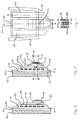
- a thin film magnetic head for use with a tape apparatus includes Permalloy magnetic layers P1 and P2 which form a magnetic yoke with a transducing gap G therebetween.
- the P1 and P2 layers are deposited over a ceramic substrate 40.
- a via or through hole 28 is provided to allow the P1 and P2 layers to make contact and form a back closure 29, thereby forming a continuous magnetic path interrupted by the nonmagnetic transducing gap.
- a conductive coil or winding 10, made of copper turns, is embedded in an insulating material 12 which is deposited between the P1 and P2 layers.
- an MR sensor 19 having a defined easy axis of magnetization is provided along the magnetic circuit path in an interspace or well between portions P2A and P2B of the central section of the P2 layer.
- the length of the MR sensor can be made longer than the width of the recorded tracks since the lateral sensitivity is determined by the width of the pole tips and not by the length of the MR transducer.
- a valve conductor 18 is formed between Permalloy layers 14 and 16 which are deposited above the insulating layer 21 and the P2 layer.
- the Permalloy layers 14 and 16 are in contact with the P2 layer thereby forming a continuous flux path for completing the write magnetic circuit.
- the valve conductor 18 is formed from one or more copper turns with insulation provided between them and the Permalloy layers 14 and 16.
- the valve conductor 18 and the magnetic layers 14 and 16 form a magnetic valve capable of opening and closing the magnetic shunt path provided by layers 14 and 16.
- the pattern of each of the P1 and P2 Permalloy layers includes a central section 24 bounded by closely spaced side yoke sections 22 and 26, which are substantially mirror images of each other.
- the sections 24, 22 and 26 of the P2 layer are in substantial vertical alignment with the respective sections of the P1 layer.
- the pole tip region of the P1 and P2 layers is narrowed to define the width of the transducing gap.
- Each of the side sections 22 and 26 is separated but closely spaced from the central section 24 by about 1-4 micrometers (microns), by way of example.
- the outer side sections 22 and 26 act as shields during the read mode thereby improving off-track performance of the tape apparatus.
- the width of the central yoke section 24 can range from about 15 to 60 microns and the widths of the side yoke sections 22, 26 can range from about 5-60 microns.
- a write track 30 having a width W w substantially equal to the total width of the transducing gap G is recorded.
- the track 30 may be recorded longitudinally, helically, transversely or by perpendicular or vertical recording techniques.
- the width of the write track 30 that is registersd during the write mode is defined by closely spaced track portions 30L, 30C, 30R that are recorded and have a width corresponding to the total width of the transducing gap formed by yoke sections 22, 24, 26 at the air bearing surface, i.e., at the transducing gap.
- the valve conductor 18 is not energized and is inactive so that the signals representing data to be recorded bypass the MR element 19 and are directed through the Permalloy branches 14 and 16 that surround the valve conductor 18.
- the write data signals are transduced at the nonmagnetic gap G and recorded on a storage medium, such as a magnetic tape.
- a current of about 25 milliampere turns, for example, is applied to the valve conductor 18 to saturate the magnetic material of the Permalloy layers 14 and 16.
- the magnetic layers 14 and 16 together have substantially the same thickness as the P2 layer, which may be about 2 to 3 microns by way of example.
- the MR element needs to be energized with a DC current.
- MR element 19 and valve conductor 18 can be dimensioned in such a way so that they are connected in series. This does not significantly affect the read efficiency, since the MR element 19 has a much higher resistance than valve conductor 18.
- a DC bias field may be generated at MR element 19, making any other biasing means unnecessary.
- Auxiliary bias of the MR element if needed, can be provided by soft bias, permanent magnet bias or shunt bias means, as is known in the art. Additionally, longitudinal bias can also be provided by antiferromagnetic or permanent magnet bias means.
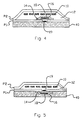
- the MR sensor 19 is located in a hiatus or interspace in the P1 layer, instead of the P2 layer as in the embodiment depicted in Fig. 2. Accordingly, in the implementation of Fig. 4, the valve conductor structure, which includes elements 14, 16 and 18, is located above the MR sensor 19 and below the coil 10.
- the MR sensor 19 is also located in the interspace in the P1 layer, but the valve conductor assembly, including elements 14, 16 and 18, is inverted and disposed in a recess formed in the substrate 40.
- wiring and vias are used to make the necessary electrical connections, including connection to external circuitry, but are not completely shown for convenience and clarity of illustration of the drawing.
- the invention disclosed herein solves several problems that have been encountered with read-write magnetic heads using flux sensors for the read function, whereby manufacturing tolerance problems are alleviated.
- the write wide, read narrow thin film head affords proper track following and improved off-track performance.
- the problem of alignment of the MR read element and the write transducer is obviated by virtue of the novel configuration. Also, thermal noise spikes and Barkhausen noise are eliminated or minimized.
- the read signal output is significantly improved with an enhanced signal-to-noise ratio.
- the device disclosed herein affords a higher spatial resolution than a conventional MR read head because the gap length can be made smaller than that of a conventional MR head.
- the MR element can be placed sufficiently far away from the pole tips to experience only negligible temperature excursions during contact with asperities of the magnetic medium surface.
Landscapes
- Engineering & Computer Science (AREA)
- Manufacturing & Machinery (AREA)
- Magnetic Heads (AREA)
Applications Claiming Priority (2)
| Application Number | Priority Date | Filing Date | Title |
|---|---|---|---|
| US10366993A | 1993-08-10 | 1993-08-10 | |
| US103669 | 1993-08-10 |
Publications (2)
| Publication Number | Publication Date |
|---|---|
| EP0638893A2 true EP0638893A2 (fr) | 1995-02-15 |
| EP0638893A3 EP0638893A3 (fr) | 1996-05-15 |
Family
ID=22296415
Family Applications (1)
| Application Number | Title | Priority Date | Filing Date |
|---|---|---|---|
| EP94112441A Withdrawn EP0638893A3 (fr) | 1993-08-10 | 1994-08-09 | Tête magnétique avec élément détecteur de flux pour enregistrer/reproduire sur une bande. |
Country Status (2)
| Country | Link |
|---|---|
| EP (1) | EP0638893A3 (fr) |
| JP (1) | JPH07153023A (fr) |
Cited By (1)
| Publication number | Priority date | Publication date | Assignee | Title |
|---|---|---|---|---|
| EP0675486A3 (fr) * | 1994-03-31 | 1997-02-26 | Read Rite Corp | Transducteur magnétorésistif à culasse intégrée et dérivation magnétique. |
Families Citing this family (1)
| Publication number | Priority date | Publication date | Assignee | Title |
|---|---|---|---|---|
| JP2006252620A (ja) * | 2005-03-09 | 2006-09-21 | Hitachi Global Storage Technologies Netherlands Bv | 磁気ヘッド及びその製造方法 |
Family Cites Families (5)
| Publication number | Priority date | Publication date | Assignee | Title |
|---|---|---|---|---|
| US3921217A (en) * | 1971-12-27 | 1975-11-18 | Ibm | Three-legged magnetic recording head using a magnetorestive element |
| US4150408A (en) * | 1975-07-17 | 1979-04-17 | U.S. Philips Corporation | Thin-film magnetic head for reading and writing information |
| US5097372A (en) * | 1989-08-04 | 1992-03-17 | Matsushita Electric Industrial Co., Ltd. | Thin film magnetic head with wide recording area and narrow reproducing area |
| JPH0383213A (ja) * | 1989-08-24 | 1991-04-09 | Matsushita Electric Ind Co Ltd | 薄膜磁気ヘッド |
| US5255141A (en) * | 1991-12-16 | 1993-10-19 | Read-Rite Corp. | Read-write magnetic head with flux sensing read element |
-
1994
- 1994-08-09 EP EP94112441A patent/EP0638893A3/fr not_active Withdrawn
- 1994-08-10 JP JP18854794A patent/JPH07153023A/ja active Pending
Cited By (1)
| Publication number | Priority date | Publication date | Assignee | Title |
|---|---|---|---|---|
| EP0675486A3 (fr) * | 1994-03-31 | 1997-02-26 | Read Rite Corp | Transducteur magnétorésistif à culasse intégrée et dérivation magnétique. |
Also Published As
| Publication number | Publication date |
|---|---|
| EP0638893A3 (fr) | 1996-05-15 |
| JPH07153023A (ja) | 1995-06-16 |
Similar Documents
| Publication | Publication Date | Title |
|---|---|---|
| US6078479A (en) | Magnetic tape head with flux sensing element | |
| US5255141A (en) | Read-write magnetic head with flux sensing read element | |
| US4663685A (en) | Magnetoresistive read transducer having patterned longitudinal bias | |
| US5822153A (en) | Hard disk drive having contact write and recessed magnetorestive read head | |
| US5446613A (en) | Magnetic head assembly with MR sensor | |
| EP0911810B1 (fr) | Dispositifs à jonction tunnel magnétique | |
| US5111352A (en) | Three-pole magnetic head with reduced flux leakage | |
| US5434733A (en) | Planar head having separate read and write gaps | |
| KR100331413B1 (ko) | 자기저항효과형재생헤드및그재생헤드를탑재한자기디스크장치 | |
| US4255772A (en) | Read/write magnetic head assembly with magnetoresistive sensor | |
| US5436779A (en) | Integrated yoke magnetoresistive transducer with magnetic shunt | |
| JP3551099B2 (ja) | 磁気テープ装置用薄膜磁気ヘッド | |
| EP0111755B1 (fr) | Transducteur magnétique à double élément | |
| US5949624A (en) | Horizontal shared-pole magnetic read/write head having polarization conductor disabling write pole | |
| US20060152851A1 (en) | Planar servo format verifier head | |
| JPH0773416A (ja) | Mr形読出しトランスジューサおよびその読出し方法 | |
| US6369992B1 (en) | Yoke-type head with magneto-resistance effect film recessed from medium facing surface and extending across magnetic gap | |
| KR0145034B1 (ko) | 자기 트랜스듀서와, 자기 트랜스듀서를 포함하는 매체 드라이브 | |
| JPH064832A (ja) | 複合型薄膜磁気ヘッド | |
| JP2002133615A (ja) | 磁気抵抗効果型磁気ヘッド | |
| JPS61120318A (ja) | 一体化薄膜磁気ヘツド | |
| JP4081937B2 (ja) | 回転型磁気ヘッド装置の製造方法 | |
| US6529352B1 (en) | Magnetoresistive sensing element and magnetic head using the magnetoresistive sensing element | |
| JP2001517309A (ja) | 磁気抵抗を用いた磁場センサ | |
| US6333840B1 (en) | Magnetic recording apparatus |
Legal Events
| Date | Code | Title | Description |
|---|---|---|---|
| PUAI | Public reference made under article 153(3) epc to a published international application that has entered the european phase |
Free format text: ORIGINAL CODE: 0009012 |
|
| AK | Designated contracting states |
Kind code of ref document: A2 Designated state(s): DE FR GB NL |
|
| PUAL | Search report despatched |
Free format text: ORIGINAL CODE: 0009013 |
|
| AK | Designated contracting states |
Kind code of ref document: A3 Designated state(s): DE FR GB NL |
|
| STAA | Information on the status of an ep patent application or granted ep patent |
Free format text: STATUS: THE APPLICATION IS DEEMED TO BE WITHDRAWN |
|
| 18D | Application deemed to be withdrawn |
Effective date: 19961116 |