EP0638965A2 - Assemblage de connecteur de traversée circulaire - Google Patents
Assemblage de connecteur de traversée circulaire Download PDFInfo
- Publication number
- EP0638965A2 EP0638965A2 EP94112587A EP94112587A EP0638965A2 EP 0638965 A2 EP0638965 A2 EP 0638965A2 EP 94112587 A EP94112587 A EP 94112587A EP 94112587 A EP94112587 A EP 94112587A EP 0638965 A2 EP0638965 A2 EP 0638965A2
- Authority
- EP
- European Patent Office
- Prior art keywords
- housing
- panel
- connector
- locking ring
- assembly
- Prior art date
- Legal status (The legal status is an assumption and is not a legal conclusion. Google has not performed a legal analysis and makes no representation as to the accuracy of the status listed.)
- Granted
Links
- 238000007789 sealing Methods 0.000 claims abstract description 42
- 230000013011 mating Effects 0.000 claims description 28
- 230000014759 maintenance of location Effects 0.000 claims description 5
- 230000008878 coupling Effects 0.000 claims description 2
- 238000010168 coupling process Methods 0.000 claims description 2
- 238000005859 coupling reaction Methods 0.000 claims description 2
- 230000003287 optical effect Effects 0.000 description 4
- 230000004048 modification Effects 0.000 description 3
- 238000012986 modification Methods 0.000 description 3
- 230000008901 benefit Effects 0.000 description 2
- LDVVMCZRFWMZSG-UHFFFAOYSA-N captan Chemical compound C1C=CCC2C(=O)N(SC(Cl)(Cl)Cl)C(=O)C21 LDVVMCZRFWMZSG-UHFFFAOYSA-N 0.000 description 2
- 230000007246 mechanism Effects 0.000 description 2
- 238000000034 method Methods 0.000 description 2
- 230000000717 retained effect Effects 0.000 description 2
- 230000006835 compression Effects 0.000 description 1
- 238000007906 compression Methods 0.000 description 1
- 239000000428 dust Substances 0.000 description 1
- 230000005489 elastic deformation Effects 0.000 description 1
- 239000007788 liquid Substances 0.000 description 1
- 239000002184 metal Substances 0.000 description 1
Images


Classifications
-
- H—ELECTRICITY
- H01—ELECTRIC ELEMENTS
- H01R—ELECTRICALLY-CONDUCTIVE CONNECTIONS; STRUCTURAL ASSOCIATIONS OF A PLURALITY OF MUTUALLY-INSULATED ELECTRICAL CONNECTING ELEMENTS; COUPLING DEVICES; CURRENT COLLECTORS
- H01R13/00—Details of coupling devices of the kinds covered by groups H01R12/70 or H01R24/00 - H01R33/00
- H01R13/64—Means for preventing incorrect coupling
- H01R13/645—Means for preventing incorrect coupling by exchangeable elements on case or base
- H01R13/6456—Means for preventing incorrect coupling by exchangeable elements on case or base comprising keying elements at different positions along the periphery of the connector
-
- H—ELECTRICITY
- H01—ELECTRIC ELEMENTS
- H01R—ELECTRICALLY-CONDUCTIVE CONNECTIONS; STRUCTURAL ASSOCIATIONS OF A PLURALITY OF MUTUALLY-INSULATED ELECTRICAL CONNECTING ELEMENTS; COUPLING DEVICES; CURRENT COLLECTORS
- H01R13/00—Details of coupling devices of the kinds covered by groups H01R12/70 or H01R24/00 - H01R33/00
- H01R13/46—Bases; Cases
- H01R13/52—Dustproof, splashproof, drip-proof, waterproof, or flameproof cases
- H01R13/5202—Sealing means between parts of housing or between housing part and a wall, e.g. sealing rings
-
- H—ELECTRICITY
- H01—ELECTRIC ELEMENTS
- H01R—ELECTRICALLY-CONDUCTIVE CONNECTIONS; STRUCTURAL ASSOCIATIONS OF A PLURALITY OF MUTUALLY-INSULATED ELECTRICAL CONNECTING ELEMENTS; COUPLING DEVICES; CURRENT COLLECTORS
- H01R13/00—Details of coupling devices of the kinds covered by groups H01R12/70 or H01R24/00 - H01R33/00
- H01R13/73—Means for mounting coupling parts to apparatus or structures, e.g. to a wall
- H01R13/74—Means for mounting coupling parts in openings of a panel
-
- H—ELECTRICITY
- H01—ELECTRIC ELEMENTS
- H01R—ELECTRICALLY-CONDUCTIVE CONNECTIONS; STRUCTURAL ASSOCIATIONS OF A PLURALITY OF MUTUALLY-INSULATED ELECTRICAL CONNECTING ELEMENTS; COUPLING DEVICES; CURRENT COLLECTORS
- H01R13/00—Details of coupling devices of the kinds covered by groups H01R12/70 or H01R24/00 - H01R33/00
- H01R13/62—Means for facilitating engagement or disengagement of coupling parts or for holding them in engagement
- H01R13/623—Casing or ring with helicoidal groove
Definitions
- This invention relates to a circular connector mountable to a bulkhead or panel and comprising sealing means.
- the circular bulkhead connectors commonly comprise sealing means such as a flexible rubber boot that is mounted around the connector and cables on the engine compartment side. Examples of such bulkhead connectors are shown in German patent application P 4306806.5 and Great Britain patent application 9204894.1.
- one of the connector parts is usually mountable to the bulkhead and the other connector part can be mated therewith at an ulterior stage in the assembly procedure.
- connection mechanisms for coupling circular connectors is a bayonet type of mechanism, whereby one connector part is rotated relative to the other as the mating terminals are pushed together.
- the panel mounted connector part is usually the part found on the passenger compartment side, which doesn't require any sealing means.
- the other connector part comprising the rubber boot and sealing means is then connected thereto.
- a panel mount connector comprising a first connector part mountable to a panel and a second connector part matable to the first part characterized in that the connector comprises a sealing ring mountable to the first connector part from one side of the panel when the first connector part is inserted to a hole in the panel from the other side thereof, whereby the sealing ring provisionally holds the first connector part to the panel prior to mating with the second connector part, and whereby the sealing ring acts as a seal between one side and the other side of the panel when the first and second connector parts are mated together.
- the second connector part comprises a housing for receiving electrical, optical, or pneumatic terminals and a rotatable locking ring for securing the second to the first connector part
- the housing comprising rubber boot fixing means around the periphery thereof proximate a terminal receiving end
- the locking ring comprising a shroud whereby the locking ring is slidable from a first position away from the rubber boot fixing means to a second position proximate the means such that the shroud extends at least partially thereover for preventing removal of the rubber boot therefrom.
- Yet another object of this invention has been achieved by providing a panel mount connector whereby the first connector part comprises compartments for slidably receiving distinct modules having terminals mounted therein, the terminal modules securely fixable within the compartments.
- a circular bulkhead connector 2 comprises a panel mount connector 4 mounted to a panel 6, and a movable connector 8.
- the panel mount connector 4 comprises a sealing and provisional mounting ring 10, a terminal module receiving housing 12 and a terminal module retention cap 14.
- the movable connector 8 comprises a terminal receiving housing 16, a locking ring 18 rotatably mounted thereon and a rubber boot 20.
- the terminal module receiving housing 12 comprising a plurality of distinct terminal module receiving cavities 22, encompassed by an inner shell 24 and an outer shell 26 spaced therefrom by a mating connector shroud receiving cavity 28.
- the housing 12 further comprises a flange 30 proximate a mating end 32, the flange 30 having a polarizing gap 31, and extending therefrom towards the mating side 32 is a shroud 34 having three helicoidal grooves 36 for receiving the mounting and sealing ring 10.
- the grooves 36 have slots 38 on a mating side 32 thereof for enabling tabs of the ring 10 to enter thereinto, and separating the entry slots 38 and the ends of the helicoidal grooves 36 is a wall 39.
- the end cap 14 comprises an end wall 54 having terminal module receiving holes 56, housing latch receiving holes 58 cooperable with the latches 46, and a locking protrusion 60 attached on a resilient arm 62.
- Extending from the periphery of the end wall 54 is a serrated cylindrical wall 64 having a tab portion 66 extending further therefrom towards the mating side for ensuring the locked position of the end cap to the component housing 12 before mounting to the panel 6.
- On the inner side of the cylindrical wall 64 is a longitudinal protrusion 68 engageable between the protrusions 50, 52 of the housing component 12, and contiguous therewith is a longitudinal trough 69 that is wide enough to span the protrusions 50, 52.
- a terminal module generally shown at 70 comprises a housing 72 having a plurality of terminal receiving cavities 74 therein, into which terminals can be inserted and securely retained as commonly found in the prior art.
- the terminal module 70 also comprises a polarizing projection 76.
- a plurality of distinct terminal modules 70 with any possible combination of terminals or types of terminals (e.g. electrical, optical) are provided for assembly into the housing component 12.
- a circular cavity 77 is also shown, the cavity 77 for receiving a vacuum pipe terminal (pneumatic pipe) which is used, for example, in the central locking system of an automobile.
- the mating pipe terminals (not shown) comprise a smaller diameter and a larger diameter pipe secured respectively to the panel and movable connectors 4, 8, whereby elastomeric "O"-ring seals provide sealing between the smaller pipe inserted into the larger pipe during connection therebetween.
- the end cap 14 is first assembled to the housing 12 by inserting it over the terminal receiving face 44 thereof until the latches 48, 46 of the housing 12 engage with the cavities 58 of the end cap for secure retention thereof. During the latter, the end cap is orientated such that the holes 56 are aligned with the corresponding terminal module receiving cavities 22 and whereby the longitudinal trough 69 in the inside of the end cap wall 64 is positioned over the longitudinal protrusions 50, 52 of the housing outer wall 26.
- the terminal modules 70 can then be inserted into their corresponding cavities 56 whereby the polarizing protrusion 76 cooperate with polarizing grooves 57 in order to correctly orientate the terminal modules with respect thereto.
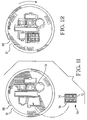
- the end cap 14 can then be rotated by a few degrees as shown in Figure 12 such that the holes 56 and cavities 22 are misaligned.
- the longitudinal projection 68 on the inside of the end cap cylindrical wall 64 resiliently biases over the longitudinal projection 50 of the housing 12 and seats itself between the projections 50, 52 when the end cap is in the fully rotated end position.
- the projection 60 ( Figure 10) engages in a corresponding cavity 79 ( Figure 2) on the terminal receiving side of the housing 12 which serves to further retain the end cap in it's fully rotated and locked position.
- the forwardly extending tab 66 of the end cap partially overlaps the panel tab mounting gap 31 as shown in Figure 11.
- the tab 66 is rotated out of it's overlapping position with the panel tab receiving gap 31 such that the panel mount connector 4 can be mounted to the panel 6.
- the movable component housing 16 comprises a terminal receiving portion 78 and a mating portion 80 having a shroud 82 extending from the terminal receiving portion 78, the shroud 82 insertable into the gap 28 ( Figure 4) of the panel mount housing 12.
- the terminal receiving portion 78 comprises a plurality of terminal receiving cavities 84.
- a tapered rubber boot mounting flange 86 proximate a terminal receiving end 88, and spaced therefrom towards a mating side 90, is a radial flange 92 and further spaced therefrom towards the mating side 90 is a cylindrical seal mounting surface 94 for receiving an elastomeric seal 96 ( Figure 25).
- the shroud 82 comprises locking ring mounting latches 98 spaced therearound. Within the shroud 82, are keying projections 100 extending from the mating face 90 longitudinally along the inside of the shroud 82.
- the sealing and provisional mounting ring 10 will be described in detail (see also Figure 1).
- the ring 10 comprises an inner ridged mounting ring 102 and mounted thereon an outer elastomeric sealing ring 104.
- the mounting ring 102 comprises a plurality of equally spaced apart tabs 106 projecting radially inwards on one side of the mounting ring 102 and another set of similar tabs 108 attached to the other side of the mounting ring whereby the tabs 106 are offset rotationally by a small angle A to the tabs 108.
- the locking ring 18 comprises a housing 110 having a cylindrical cavity 112 therethrough substantially closely mountable over the shroud 82 of the movable connector housing 16, a radially outwardly extending flange 114 having a forwards sealing surface 116 pressable against the seal 104, and adjacent the flange 114 on the other side to the sealing face 116 is a crowned ring shroud 118 for receiving a tool for rotating the locking ring 18.
- a thin walled ring portion 120 comprising a plurality of spiraling grooves 119 (bayonet type) for receiving the cylindrical studs 40 ( Figure 3) of the panel mount connector 12, the groove 119 having a stud entry passage 121 at a forward end thereof.
- the ring portion 120 also comprises a plurality of rectangular cavities 122 therearound for receiving the latches 98 ( Figure 13) of the movable housing components 16, and a forward edge 123 also engageable with the latches 98.
- a conical cavity section 124 Extending from the cavity 112 and radially below the crowned ring 118.
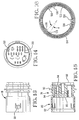
- the panel 6 is shown comprising a cutout 124 for receiving the panel mount connector housing 12, and bent perpendicularly therefrom, a tab 126 projecting towards the panel housing 12 and engageable in the gap 31 thereof.
- the panel mount component 4 comprises, prior to assembly to the panel 6, terminals mounted in the terminal modules 70 fully assembled to the housing 12 and locked therein with the end cap 14, whereby the terminals are connected to electrical conducting cables, optical cables or pneumatic pipes (not shown for simplicity).
- the assembled panel mount component 4 can then be assembled to the panel 6 by aligning it with the panel hole 124 whereby the panel tab 126 is aligned with the flange gap 31 of the housing 12.
- the mounting and sealing ring 10 can then be assembled thereto by aligning the tabs 106 thereof with the gaps 38 at the entry of the spiral grooves 36 of the housing 12 ( Figure 5), and then inserting the tabs thereinto and rotating the ring 10 such that the tabs 106 travel along their corresponding grooves 36. Whilst the tabs 106 travel along the grooves 36, the other set of tabs 108 on the other side of the mounting ring 102 remain outside of the grooves 36 along the outer edge 37.
- the tabs 106 When the ring 10 is fully rotated, the tabs 106 abut the end wall 39 of the grooves 36 whereby the tabs 106 and 108 are angularly misaligned such that the tabs 108 become aligned with the gaps 38. In the latter position as the tabs 106 are within the grooves 36, the ring 10 provisionally holds the panel mount component to the panel 6.
- the purpose of the tabs 108 aligned with the grooves 38 in the fully rotated position, is to allow axial movement of the ring 10 towards the panel 6, whereby during this axial movement the tabs 108 enter into the gaps 38 such that the tabs 108 prevent the ring 10 from rotating open by abutting the end wall 39 on the other side thereof than the tabs 106.
- the purpose of the latter is to stop rotation of the ring 10 during disconnection of the movable connector 8 in order to ensure that the ring 10 continues to hold the panel mount component 4 to the panel 6 during this operation.
- the further purpose of allowing axial movement of the ring 10 is to enable axial movement thereof during compression of the seal 104 when the connector parts 8 and 4 are mated together. If the tabs 108 did not engage in the gap 38 when fully rotated to the housing 12, rotation of the locking ring 18 during unmating of the connector part 8 from the connector part 4 might cause the ring 10 to rotate also due to the frictional forces, such that the tabs 106 travel back along the grooves 36 and out of the gaps 38. This in turn would probably cause the housing 12 to fall away from the panel 6 which is obviously undesirable.
- the sealing ring 10 can be mounted from either side thereof, which is advantageous as it eliminates the possibility of error and the need to orientate the ring 10 during assembly.
- the locking ring 18 is first mounted to the housing 16 by sliding it over the shroud 82 thereof until the latches 98 engage in the windows 122 of the locking ring.
- the latter defines a preassembled position whereby the cooperation of the latches 98 and windows 122 provisionally hold the locking ring 18 to the housing 16 yet allow assembly of terminals into the receiving cavities 84 prior to mounting of the rubber boot 20.
- the moveable connector 8 can not be mated with the panel mount connector 4 because the locking ring 18 can not rotate relative to the housing 16.
- Terminals (not shown) can then be mounted and securely locked into the terminal receiving cavities 84, whereby around the terminals is loosely positioned the rubber boot 20 which is then pulled over the rubber boot mounting flange 86.
- the tapered leading edge of the mounting flange 86 facilitates pulling of a forwards mounting portion 120 of the rubber boot thereover by elastic deformation thereof.
- the mounting portion 120 then seats itself behind a shoulder of the flange 86.
- the rubber boot is also stopped from sliding further forwards by the flange 92. In the position as shown in Figure 26, the rubber boot can be removed from around the flange 86 by exerting sufficient force, either accidentally during handling thereof, or purposefully if access is required to the terminals.
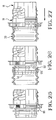
- the locking ring 18 is pulled towards the rubber boot such that the housing latches 98 are resiliently biased inwards as the locking ring windows 122 slide therepast, whereby the latches 98 then engage and abut the forward edge 123 of the locking ring to secure the locking ring in the most rearward position.
- the inner conical surface 124 of the crowned ring 118 is inserted partially over the mounting portion 120 of the rubber boot. In this position the rubber boot 20 can no longer be pulled off the mounting flange 86 of the connector housing 16.
- the rubber boot mounting portion 120 As the rubber boot mounting portion 120 is resiliently biased outwards, it abuts the conical surface 124 and prevents further resilient biasing outwards thereof thus remaining captured behind the shoulder of the flange 86.
- the flange 92 of the housing 16 prevents further rearward sliding of the locking ring 18 which is however free to rotate.
- the elastomeric seal 96 is compressed between the cylindrical inner surface of the locking ring and the cylindrical seal mounting surface 94 of the housing 16 for sealing therebetween.
- the movable connector part 8 is rotatably orientated until the keying projections 100 align with the keying slots 41 of the panel mount housing 12, whereby the movable housing 16 can then be partially inserted into the housing 12 until the forward end 123 of the locking ring 18 abuts the panel housing studs 40.
- the locking ring can then be freely rotated until the studs 40 engage into the bayonet type spirals 119, 121 of the locking ring which is then rotated by hand or using a tool engaging the serrations of the crowned ring shroud 118 thereby approaching the connector parts 8 and 4 until the studs 40 abut with the end of the spirals 119.
- the sealing surface 116 of the locking ring flange 114 compresses the sealing ring 104 against the panel 6 thereby sealing therebetween. Also simultaneously to the latter, is the mating of the terminals of the movable connector 8 to the panel connector 4.
- the connector parts 8 and 4 are thus fully mated together and the movable connector side 8 sealed off from the panel mount connector side 4.
- the panel mount connector 4 can be easily and rapidly mounted and dismounted to the panel 6 by use of the sealing and provisional mounting means 10.
- the panel mount connector 4 is also advantageous in that terminals are first mounted into distinct modules 70 which can then be rapidly inserted into corresponding cavities 22 of the panel connector housing 12; and then securely retained therein by mere rotation of the end cap whereby the end cap has tab means 66 which prevent mounting of the panel connector 4 to the panel 6 if the terminal modules are not securely locked therein.
- the use of terminal modules 70 allows cable harnesses stemming from different locations to be mounted into the panel mount connector 4, which reduces the number of harnesses and holes that would have to made into the panel 6 as opposed to each terminal module 70 fed and mated individually.
- a new panel mount connector 4 can be produced without changing exterior dimensions and thus remain mountable to the same panel hole 124. This is an important aspect especially in the automobile industry where changing, or adding a panel hole 124 requires modification to the stamping and forming die which is very costly.
- Advantages of the movable connector part is the retractable locking ring 18 in order to protect the rubber boot from being pulled off. A further advantage is also the shroud 82 which entirely surrounds and protect the terminals that project from the mating face 90 of the movable connector housing 16.
Landscapes
- Connector Housings Or Holding Contact Members (AREA)
Priority Applications (1)
| Application Number | Priority Date | Filing Date | Title |
|---|---|---|---|
| EP98108779A EP0863579B1 (fr) | 1993-08-13 | 1994-08-11 | Assemblage de connecteur de traversée circulaire |
Applications Claiming Priority (2)
| Application Number | Priority Date | Filing Date | Title |
|---|---|---|---|
| GB9316838 | 1993-08-13 | ||
| GB939316838A GB9316838D0 (en) | 1993-08-13 | 1993-08-13 | Circular bulkhead connector assembly |
Related Child Applications (1)
| Application Number | Title | Priority Date | Filing Date |
|---|---|---|---|
| EP98108779A Division EP0863579B1 (fr) | 1993-08-13 | 1994-08-11 | Assemblage de connecteur de traversée circulaire |
Publications (3)
| Publication Number | Publication Date |
|---|---|
| EP0638965A2 true EP0638965A2 (fr) | 1995-02-15 |
| EP0638965A3 EP0638965A3 (fr) | 1995-11-22 |
| EP0638965B1 EP0638965B1 (fr) | 1998-12-09 |
Family
ID=10740438
Family Applications (2)
| Application Number | Title | Priority Date | Filing Date |
|---|---|---|---|
| EP94112587A Expired - Lifetime EP0638965B1 (fr) | 1993-08-13 | 1994-08-11 | Assemblage de connecteur de traversée circulaire |
| EP98108779A Expired - Lifetime EP0863579B1 (fr) | 1993-08-13 | 1994-08-11 | Assemblage de connecteur de traversée circulaire |
Family Applications After (1)
| Application Number | Title | Priority Date | Filing Date |
|---|---|---|---|
| EP98108779A Expired - Lifetime EP0863579B1 (fr) | 1993-08-13 | 1994-08-11 | Assemblage de connecteur de traversée circulaire |
Country Status (8)
| Country | Link |
|---|---|
| US (1) | US5618204A (fr) |
| EP (2) | EP0638965B1 (fr) |
| JP (1) | JP3492773B2 (fr) |
| CN (1) | CN1084062C (fr) |
| BR (1) | BR9403243A (fr) |
| DE (2) | DE69424694T2 (fr) |
| ES (1) | ES2126681T3 (fr) |
| GB (1) | GB9316838D0 (fr) |
Cited By (8)
| Publication number | Priority date | Publication date | Assignee | Title |
|---|---|---|---|---|
| EP0893852A3 (fr) * | 1997-07-25 | 1999-11-10 | Itt Manufacturing Enterprises, Inc. | Connecteur avec bride de montage amovible |
| EP0982814A3 (fr) * | 1998-08-28 | 2002-05-22 | Itt Manufacturing Enterprises, Inc. | Connecteur d'appareil |
| DE10138120A1 (de) * | 2001-08-03 | 2003-02-27 | Bosch Gmbh Robert | Flanschgehäuse für einen Stecker |
| WO2008015128A1 (fr) * | 2006-08-02 | 2008-02-07 | Tyco Electronics Amp Gmbh | Connecteur de type fiche, dispositif ayant un connecteur de type fiche et procédé d'assemblage |
| EP2337164A1 (fr) * | 2009-12-17 | 2011-06-22 | Canford Audio Plc | Dispositif de fixation pour le montage d'un connecteur sur un panneau |
| CN105071109A (zh) * | 2015-08-23 | 2015-11-18 | 深圳市凯旺电子有限公司 | 一种摄像头防水连接装置及其使用方法 |
| WO2021259417A1 (fr) * | 2020-06-22 | 2021-12-30 | Harting Electric Gmbh & Co. Kg | Système de connecteurs mâles haute puissance |
| WO2025011701A1 (fr) * | 2023-07-13 | 2025-01-16 | Schaeffler Technologies AG & Co. KG | Unité de couplage électrique pour la traversée de boîtier d'un courant de puissance ht, et machine d'entraînement électrique |
Families Citing this family (30)
| Publication number | Priority date | Publication date | Assignee | Title |
|---|---|---|---|---|
| DE29721908U1 (de) * | 1997-12-11 | 1998-02-12 | Leopold Kostal GmbH & Co KG, 58507 Lüdenscheid | Anordnung betreffend eine elektrische und/oder elektronische Bauelemente tragende Elektrikplatte mit einem elektrischen Steckverbinder und einer Abdeckung |
| DE19848725B4 (de) * | 1998-10-22 | 2006-08-31 | Zf Friedrichshafen Ag | Elektrische Steckverbindung |
| US6475009B2 (en) | 2000-06-02 | 2002-11-05 | The Siemon Company | Industrial telecommunications connector |
| US6358063B1 (en) | 2000-06-28 | 2002-03-19 | Intercon Systems, Inc. | Sealed interposer assembly |
| JP4348879B2 (ja) * | 2001-07-17 | 2009-10-21 | 住友電装株式会社 | 機器用コネクタ装置 |
| US6666701B1 (en) | 2002-07-22 | 2003-12-23 | Signet Scientific Company | Bayonet-type electrical connector assembly |
| US20050064752A1 (en) * | 2003-02-28 | 2005-03-24 | Alden Products Company | Ruggedized ethernet connector assembly |
| US6913402B2 (en) * | 2003-08-07 | 2005-07-05 | Stratos International, Inc. | Bulkhead mountable optoelectronic device |
| US7018226B2 (en) | 2004-01-09 | 2006-03-28 | Hubbell Incorporated | Electrical connector having a spring to facilitate mounting |
| WO2006083787A1 (fr) * | 2005-01-31 | 2006-08-10 | Panduit Corp. | Orientation de broche de connecteur ethernet |
| US7128616B1 (en) | 2005-08-15 | 2006-10-31 | Woven Electronics Corporation | High speed data transmission cable connector system |
| US20070177366A1 (en) * | 2006-01-27 | 2007-08-02 | Stewart William P | Alignment and coupling of electronics housings to electric machines |
| WO2007134634A1 (fr) * | 2006-05-18 | 2007-11-29 | Auto Kabel Managementgesellschaft Mbh | Profilé électrique pour traversées de câbles |
| GB201002996D0 (en) | 2010-02-23 | 2010-04-07 | Airbus Operations Ltd | Electrical connector |
| JP5806523B2 (ja) * | 2011-06-24 | 2015-11-10 | 矢崎総業株式会社 | グロメット付きコネクタ |
| US8425244B2 (en) * | 2011-07-26 | 2013-04-23 | Motorola Solutions, Inc. | Connector with a locking sleeve for locking to a socket having a circular band |
| JP5818358B2 (ja) * | 2012-01-30 | 2015-11-18 | 本多通信工業株式会社 | 太陽光発電システム用コネクタ構造 |
| CN103219618B (zh) * | 2013-04-03 | 2016-03-23 | 中航光电科技股份有限公司 | 一种插座以及使用该插座的电连接器组件 |
| US10404048B2 (en) * | 2013-11-26 | 2019-09-03 | Commscope Technologies Llc | Adapter for sealing cover for electrical interconnections |
| CN104617441B (zh) * | 2014-12-23 | 2018-05-29 | 杭州航天电子技术有限公司 | 一种可游动的电连接器插头 |
| JP6620938B2 (ja) * | 2016-04-11 | 2019-12-18 | 住友電装株式会社 | コネクタ |
| DE102017201033A1 (de) * | 2017-01-23 | 2018-07-26 | Brose Fahrzeugteile GmbH & Co. Kommanditgesellschaft, Würzburg | Dichtungseinrichtung und Antriebseinheit mit 2-Komponenten-Dichtungseinrichtung |
| CN109119786B (zh) * | 2017-06-23 | 2020-11-06 | 上海电巴新能源科技有限公司 | 低压极柱及包含其的电连接器 |
| US10090615B1 (en) * | 2017-09-22 | 2018-10-02 | Te Connectivity Corporation | Panel mount electrical connector with moisture resistant mating face |
| JP6901365B2 (ja) * | 2017-09-29 | 2021-07-14 | プライムアースEvエナジー株式会社 | コネクタカバー及びコネクタアッシー |
| WO2021002876A1 (fr) * | 2019-07-04 | 2021-01-07 | Hewlett-Packard Development Company, L.P. | Connecteur |
| US11658436B2 (en) * | 2020-07-01 | 2023-05-23 | Commscope Technologies Llc | Power cable connectors and assemblies |
| JP7256155B2 (ja) * | 2020-09-30 | 2023-04-11 | 矢崎総業株式会社 | コネクタ |
| US20240113363A1 (en) * | 2022-09-30 | 2024-04-04 | Ford Global Technologies, Llc | Systems and methods for attaching peripheral components to traction battery packs |
| CN116169516A (zh) * | 2022-11-11 | 2023-05-26 | 华勤技术股份有限公司 | 连接结构及连接装置 |
Family Cites Families (21)
| Publication number | Priority date | Publication date | Assignee | Title |
|---|---|---|---|---|
| US2666804A (en) * | 1950-08-15 | 1954-01-19 | Rohr Aircraft Corp | Lead-in terminal |
| US2666805A (en) * | 1951-02-03 | 1954-01-19 | Rohr Aircraft Corp | Lead-in terminal |
| US2672500A (en) * | 1951-09-19 | 1954-03-16 | Lewis A Bondon | Pressurized multiconductor bulkhead connector assembly |
| GB881956A (en) * | 1958-06-05 | 1961-11-08 | Bush And Rank Cintel Ltd | Improvements in or relating to demountable electrical connections |
| GB878221A (en) * | 1958-09-08 | 1961-09-27 | Ass Elect Ind | Improvements relating to apparatus for securing a first body within an aperture in asecond body |
| FR1333168A (fr) * | 1962-06-13 | 1963-07-26 | F Chaume Soc | Prise coaxiale notamment pour antenne d'automobile |
| US3818420A (en) * | 1970-12-07 | 1974-06-18 | Itt | Low insertion force electrical connector |
| US3719918A (en) * | 1971-11-04 | 1973-03-06 | Schlumberger Technology Corp | Electrical connector |
| US3850495A (en) * | 1973-06-06 | 1974-11-26 | Amp Inc | Multi-pin shielded high voltage connector |
| US4179179A (en) * | 1978-05-17 | 1979-12-18 | Whitaker Cable Corporation | Electrical connector having multiple terminal receptacle receiving different plugs |
| US4405196A (en) * | 1981-01-12 | 1983-09-20 | Fulton Robert W | Electrical connector for high fidelity audio equipment |
| US4483579A (en) * | 1983-03-29 | 1984-11-20 | Amp Incorporated | Electrical connector having improved coupling ring |
| US4573757A (en) * | 1983-12-14 | 1986-03-04 | Kuhlman Corporation | Transformer bushing |
| DE3507525C1 (de) * | 1985-03-04 | 1986-09-25 | Schulte-Elektrotechnik GmbH & Co KG, 5880 Lüdenscheid | Elektrischer Geraetestecker |
| US4676575A (en) * | 1986-06-19 | 1987-06-30 | Amp Incorporated | Sealing member for bulkhead connector |
| US4702710A (en) * | 1986-06-20 | 1987-10-27 | Georgia Tech Research Corporation | Waterproof seal assembly for electrical connector |
| US4773871A (en) * | 1987-06-29 | 1988-09-27 | Alden Research Foundation | High voltage bulkhead coupling |
| GB8717486D0 (en) * | 1987-07-23 | 1987-08-26 | Hamblin B D | Earth connection |
| JP2506070Y2 (ja) * | 1989-03-23 | 1996-08-07 | 株式会社東海理化電機製作所 | 自動車用電動式リモコンミラ―のコネクタ保持装置 |
| DE8911625U1 (de) * | 1989-09-29 | 1989-12-28 | Erich Jaeger GmbH & Co KG, 6380 Bad Homburg | Einrichtung zum elektrischen Anschließen der Steckdose einer mehrpoligen Steckvorrichtung |
| DE9003016U1 (de) * | 1990-03-12 | 1991-07-11 | Grote & Hartmann Gmbh & Co Kg, 5600 Wuppertal | Steckerkupplung für eine elektrische Steckerverbindung zur Durchkontaktierung einer Wand, insbesondere einer Karosseriewand eines Kraftfahrzeugs |
-
1993
- 1993-08-13 GB GB939316838A patent/GB9316838D0/en active Pending
-
1994
- 1994-06-13 US US08/258,648 patent/US5618204A/en not_active Expired - Fee Related
- 1994-07-29 JP JP19763094A patent/JP3492773B2/ja not_active Expired - Fee Related
- 1994-08-11 ES ES94112587T patent/ES2126681T3/es not_active Expired - Lifetime
- 1994-08-11 DE DE69424694T patent/DE69424694T2/de not_active Expired - Lifetime
- 1994-08-11 EP EP94112587A patent/EP0638965B1/fr not_active Expired - Lifetime
- 1994-08-11 DE DE69415101T patent/DE69415101T2/de not_active Expired - Lifetime
- 1994-08-11 EP EP98108779A patent/EP0863579B1/fr not_active Expired - Lifetime
- 1994-08-12 CN CN94109431A patent/CN1084062C/zh not_active Expired - Fee Related
- 1994-08-12 BR BR9403243A patent/BR9403243A/pt not_active IP Right Cessation
Cited By (9)
| Publication number | Priority date | Publication date | Assignee | Title |
|---|---|---|---|---|
| EP0893852A3 (fr) * | 1997-07-25 | 1999-11-10 | Itt Manufacturing Enterprises, Inc. | Connecteur avec bride de montage amovible |
| EP0982814A3 (fr) * | 1998-08-28 | 2002-05-22 | Itt Manufacturing Enterprises, Inc. | Connecteur d'appareil |
| DE10138120A1 (de) * | 2001-08-03 | 2003-02-27 | Bosch Gmbh Robert | Flanschgehäuse für einen Stecker |
| DE10138120B4 (de) * | 2001-08-03 | 2004-09-30 | Robert Bosch Gmbh | Flanschgehäuse für einen Stecker mit Verdrehschutz |
| WO2008015128A1 (fr) * | 2006-08-02 | 2008-02-07 | Tyco Electronics Amp Gmbh | Connecteur de type fiche, dispositif ayant un connecteur de type fiche et procédé d'assemblage |
| EP2337164A1 (fr) * | 2009-12-17 | 2011-06-22 | Canford Audio Plc | Dispositif de fixation pour le montage d'un connecteur sur un panneau |
| CN105071109A (zh) * | 2015-08-23 | 2015-11-18 | 深圳市凯旺电子有限公司 | 一种摄像头防水连接装置及其使用方法 |
| WO2021259417A1 (fr) * | 2020-06-22 | 2021-12-30 | Harting Electric Gmbh & Co. Kg | Système de connecteurs mâles haute puissance |
| WO2025011701A1 (fr) * | 2023-07-13 | 2025-01-16 | Schaeffler Technologies AG & Co. KG | Unité de couplage électrique pour la traversée de boîtier d'un courant de puissance ht, et machine d'entraînement électrique |
Also Published As
| Publication number | Publication date |
|---|---|
| EP0863579A3 (fr) | 1998-11-25 |
| EP0638965B1 (fr) | 1998-12-09 |
| US5618204A (en) | 1997-04-08 |
| JPH0778649A (ja) | 1995-03-20 |
| DE69415101T2 (de) | 1999-07-01 |
| DE69424694T2 (de) | 2000-11-23 |
| ES2126681T3 (es) | 1999-04-01 |
| CN1084062C (zh) | 2002-05-01 |
| EP0638965A3 (fr) | 1995-11-22 |
| GB9316838D0 (en) | 1993-09-29 |
| BR9403243A (pt) | 1995-04-11 |
| DE69415101D1 (de) | 1999-01-21 |
| JP3492773B2 (ja) | 2004-02-03 |
| EP0863579B1 (fr) | 2000-05-24 |
| EP0863579A2 (fr) | 1998-09-09 |
| DE69424694D1 (de) | 2000-06-29 |
| CN1110433A (zh) | 1995-10-18 |
Similar Documents
| Publication | Publication Date | Title |
|---|---|---|
| US5618204A (en) | Circular bulkhead connector assembly | |
| CN111641078B (zh) | 一种弹片锁紧式推拉自锁连接器 | |
| US6048229A (en) | Environmentally resistant EMI rectangular connector having modular and bayonet coupling property | |
| US6045404A (en) | Electrical connector having a terminal position assurance device | |
| US5718596A (en) | Connector engaging structure | |
| US4464001A (en) | Coupling nut having an anti-decoupling device | |
| US5338211A (en) | Connector cover structure | |
| EP0622869B1 (fr) | Dispositif de connecteur | |
| US6361348B1 (en) | Right angle, snap on coaxial electrical connector | |
| EP3680995B1 (fr) | Connecteurs de câble électrique dotés de constructions détachables et leur procédé de fonctionnement | |
| EP0977324B1 (fr) | Connecteur avec levier | |
| US5993266A (en) | Keying system for electrical connector | |
| US7407397B2 (en) | Lever-type connector and connector assembly | |
| US20250047027A1 (en) | Electrical connector assembly having floating mating interface | |
| EP4297193A1 (fr) | Ensemble connecteur électrique à éléments de verrouillage de borne flexibles et rigides | |
| KR102496203B1 (ko) | 단일조작으로 결합가능한 커넥터 어셈블리 | |
| US5551147A (en) | Tool for removing a repairable electrical connector insert | |
| US6116953A (en) | Electrical connector having a terminal position assurance device | |
| CN1218313A (zh) | 高性能连接器 | |
| CA2419352C (fr) | Ensemble de connexion electrique pour cables coaxiaux | |
| CN112310706B (zh) | 连接器以及连接器装置 | |
| EP1309045B1 (fr) | Socle pour lampe et montage | |
| EP3796479B1 (fr) | Connecteur basse tension | |
| EP4521563A1 (fr) | Presse-étoupe pour connecteur électrique et connecteur électrique | |
| EP4492587A1 (fr) | Joint de câble |
Legal Events
| Date | Code | Title | Description |
|---|---|---|---|
| PUAI | Public reference made under article 153(3) epc to a published international application that has entered the european phase |
Free format text: ORIGINAL CODE: 0009012 |
|
| AK | Designated contracting states |
Kind code of ref document: A2 Designated state(s): DE ES FR GB IT |
|
| PUAL | Search report despatched |
Free format text: ORIGINAL CODE: 0009013 |
|
| AK | Designated contracting states |
Kind code of ref document: A3 Designated state(s): DE ES FR GB IT |
|
| 17P | Request for examination filed |
Effective date: 19960311 |
|
| 17Q | First examination report despatched |
Effective date: 19970526 |
|
| GRAG | Despatch of communication of intention to grant |
Free format text: ORIGINAL CODE: EPIDOS AGRA |
|
| GRAG | Despatch of communication of intention to grant |
Free format text: ORIGINAL CODE: EPIDOS AGRA |
|
| GRAH | Despatch of communication of intention to grant a patent |
Free format text: ORIGINAL CODE: EPIDOS IGRA |
|
| GRAH | Despatch of communication of intention to grant a patent |
Free format text: ORIGINAL CODE: EPIDOS IGRA |
|
| GRAA | (expected) grant |
Free format text: ORIGINAL CODE: 0009210 |
|
| AK | Designated contracting states |
Kind code of ref document: B1 Designated state(s): DE ES FR GB IT |
|
| REF | Corresponds to: |
Ref document number: 69415101 Country of ref document: DE Date of ref document: 19990121 |
|
| ITF | It: translation for a ep patent filed | ||
| ET | Fr: translation filed | ||
| REG | Reference to a national code |
Ref country code: ES Ref legal event code: FG2A Ref document number: 2126681 Country of ref document: ES Kind code of ref document: T3 |
|
| PLBE | No opposition filed within time limit |
Free format text: ORIGINAL CODE: 0009261 |
|
| STAA | Information on the status of an ep patent application or granted ep patent |
Free format text: STATUS: NO OPPOSITION FILED WITHIN TIME LIMIT |
|
| 26N | No opposition filed | ||
| REG | Reference to a national code |
Ref country code: GB Ref legal event code: IF02 |
|
| PGFP | Annual fee paid to national office [announced via postgrant information from national office to epo] |
Ref country code: GB Payment date: 20020626 Year of fee payment: 9 |
|
| PGFP | Annual fee paid to national office [announced via postgrant information from national office to epo] |
Ref country code: FR Payment date: 20020805 Year of fee payment: 9 |
|
| PGFP | Annual fee paid to national office [announced via postgrant information from national office to epo] |
Ref country code: ES Payment date: 20020828 Year of fee payment: 9 |
|
| PG25 | Lapsed in a contracting state [announced via postgrant information from national office to epo] |
Ref country code: GB Free format text: LAPSE BECAUSE OF NON-PAYMENT OF DUE FEES Effective date: 20030811 |
|
| PG25 | Lapsed in a contracting state [announced via postgrant information from national office to epo] |
Ref country code: ES Free format text: LAPSE BECAUSE OF NON-PAYMENT OF DUE FEES Effective date: 20030812 |
|
| GBPC | Gb: european patent ceased through non-payment of renewal fee |
Effective date: 20030811 |
|
| PG25 | Lapsed in a contracting state [announced via postgrant information from national office to epo] |
Ref country code: FR Free format text: LAPSE BECAUSE OF NON-PAYMENT OF DUE FEES Effective date: 20040430 |
|
| REG | Reference to a national code |
Ref country code: FR Ref legal event code: ST |
|
| REG | Reference to a national code |
Ref country code: ES Ref legal event code: FD2A Effective date: 20030812 |
|
| PG25 | Lapsed in a contracting state [announced via postgrant information from national office to epo] |
Ref country code: IT Free format text: LAPSE BECAUSE OF NON-PAYMENT OF DUE FEES Effective date: 20050811 |
|
| PGFP | Annual fee paid to national office [announced via postgrant information from national office to epo] |
Ref country code: DE Payment date: 20130828 Year of fee payment: 20 |
|
| REG | Reference to a national code |
Ref country code: DE Ref legal event code: R071 Ref document number: 69415101 Country of ref document: DE |
|
| PG25 | Lapsed in a contracting state [announced via postgrant information from national office to epo] |
Ref country code: DE Free format text: LAPSE BECAUSE OF EXPIRATION OF PROTECTION Effective date: 20140812 |