EP0638988A2 - Selbsteinstellender Folgeregler für Permanentmagnetsynchronmotoren - Google Patents
Selbsteinstellender Folgeregler für Permanentmagnetsynchronmotoren Download PDFInfo
- Publication number
- EP0638988A2 EP0638988A2 EP94202299A EP94202299A EP0638988A2 EP 0638988 A2 EP0638988 A2 EP 0638988A2 EP 94202299 A EP94202299 A EP 94202299A EP 94202299 A EP94202299 A EP 94202299A EP 0638988 A2 EP0638988 A2 EP 0638988A2
- Authority
- EP
- European Patent Office
- Prior art keywords
- motor
- velocity
- rotor
- mathematical model
- parameter estimates
- Prior art date
- Legal status (The legal status is an assumption and is not a legal conclusion. Google has not performed a legal analysis and makes no representation as to the accuracy of the status listed.)
- Withdrawn
Links
Images


Classifications
-
- H—ELECTRICITY
- H02—GENERATION; CONVERSION OR DISTRIBUTION OF ELECTRIC POWER
- H02P—CONTROL OR REGULATION OF ELECTRIC MOTORS, ELECTRIC GENERATORS OR DYNAMO-ELECTRIC CONVERTERS; CONTROLLING TRANSFORMERS, REACTORS OR CHOKE COILS
- H02P6/00—Arrangements for controlling synchronous motors or other dynamo-electric motors using electronic commutation dependent on the rotor position; Electronic commutators therefor
- H02P6/20—Arrangements for starting
-
- H—ELECTRICITY
- H02—GENERATION; CONVERSION OR DISTRIBUTION OF ELECTRIC POWER
- H02P—CONTROL OR REGULATION OF ELECTRIC MOTORS, ELECTRIC GENERATORS OR DYNAMO-ELECTRIC CONVERTERS; CONTROLLING TRANSFORMERS, REACTORS OR CHOKE COILS
- H02P6/00—Arrangements for controlling synchronous motors or other dynamo-electric motors using electronic commutation dependent on the rotor position; Electronic commutators therefor
- H02P6/34—Modelling or simulation for control purposes
Definitions
- This invention relates generally to adaptive control of motors and more specifically to self-tuning control of permanent-magnet synchronous motors.
- Electric motors convert electrical energy into mechanical energy and come in a variety of forms and sizes depending on the specific application for which the motor is used.
- Electric motors use a magnetic field to form an energy link between an electrical system and a mechanical system.
- the magnetic field of a motor contributes to the production of mechanical output torque and induces voltages (counter emf) in coils of wire in the motor.
- the magnetic field is produced in part by permanent magnets mounted on a rotor (the rotating part of the motor).
- the stator (the stationary part of the motor) is typically wound so as to provide three sets of poles out of phase by (separated by) 120°.
- Permanent-magnet motors constructed in this fashion are generally referred to as synchronous if, when powered by three-phase alternating current, the motor operates in synchronism with the excitation frequency.
- Permanent-magnet synchronous motors are particularly appropriate for motion control applications because of their potentially very high torque-to-weight ratios, cheaper production costs, and superior thermal properties. Accordingly, permanent-magnet synchronous motors have found ready application in a wide range of environments from small computer disc drives to medium sized direct-drive robots.
- motion control systems include a controller, a motor, a load, and sensors.
- Traditional closed-loop control techniques compare a feedback signal representing the measured or sensed motor output to an input command (representing the desired motor output), then adjust the excitation applied to the motor to minimize the difference between the input command and the feedback signal.
- modem control techniques preferably should be able to adapt to the changing operating environment of the motor. For example, the electromagnetic characteristics of the motor may deviate substantially from nominal, bearings may become worn, the amount of fiction may change, the load may vary and electronics drift may occur. When such changes to the motor and its environment occur, the control system implementing traditional control techniques can no longer provide the same accuracy initially provided and required for the particular application, despite the use of feedback. In order to correct these problems, prior art techniques generally have required manual retuning. This can be a very costly and time consuming process.
- the mathematical model uses an equivalent two-phase representation of the motor in which the equations are expressed in terms of the reference fame of the rotor.
- the goal of the controller presented in this paper is to achieve invariant velocity control in the face of varying mechanical parameters.
- An inner control loop comprising the motor, its inverter, its current and velocity controllers, and a state filter, is assumed to evolve in a time scale which is faster than the time scale of an outer control loop comprising a parameter estimator and a redesign algorithm for the velocity controller.
- the controller presented suffers from the inability of the control algorithm developed to be implemented on a standard low-cost microprocessor due to the high computational burden placed on the microprocessor by the inner loop controller.
- controller presented by Sepe and Lang has limited applicability in that it is generally only applicable to permanent-magnet synchronous motors with perfectly known sinusoidal torque-angle characteristics and in which all other electrical parameters are assumed to be known and are constant. Furthermore, the controller presented by Sepe and Lang is limited to velocity control. Thus, a need yet exists for a controller for permanent-magnet synchronous motors which is applicable to permanent-magnet synchronous motors regardless of their torque-angle characteristics and in which all the electrical and mechanical parameters of the motor are unknown or vary over time. Moreover, a need still exists for a self-tuning controller for permanent-magnet synchronous motors which may be implemented with a standard, low-cost microprocessor without placing an excessive computational burden thereon.
- the present invention is directed to an inexpensive self-tuning controller for permanent-magnet synchronous motors.
- the method according to the invention comprises the steps of applying a voltage to the stator windings so as to command the motor to follow a desired position or velocity trajectory using initial estimates of the electrical and mechanical parameters of the motor in a simplified mathematical model of the motor including piecewise-linear (or piecewise-polynomial) approximations for the torque-angle characteristic functions of the motor and, optionally, a piecewise approximation for the motor load.
- Afier selecting the initial estimates of the electrical and mechanical parameters of the motor voltage is applied to the stator windings, and rotor position, velocity, and currents in the stator windings are measured.
- the measured rotor position and velocity are compared to a specified (desired) velocity or position trajectory for the motor and error signals for position and velocity are obtained. These error signals are used to develop updated parameter estimates, yielding an updated simplified mathematical model of the motor.
- Self-tuning control is obtained by subsequently applying a voltage to the stator windings so as to command the motor to follow the specified or desired position or velocity trajectory using the updated simplified mathematical model of the motor.
- the simplified model of the motor is a discrete-time, reduced-order model.
- the new piecewise-linear parameterization of the motor torque-angle characteristic functions allows for identification of higher order harmonics with a degree of accuracy which is selectable by the end user of the controller without requiring more computations than with known one-term sinusoidal representations (e.g., a one-term Fourier series) of the motor torque-angle characteristic functions.
- Excellent motor performance thereby is achieved due to computationally efficient self-tuning, even when the electrical and mechanical parameters of the motor are unknown prior to beginning operation.
- a further object of the present invention is to provide a method of controlling permanent-magnet synchronous motors which experiences minimal error in following a specified position or velocity trajectory.
- Fig. 1A is a graphical representation of a motor control arrangement which has been used to demonstrate the present invention.
- Fig. 1B is a graphical representation of a preferred, low-cost implementation of the present invention.
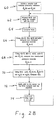
- Fig. 2A is a schematic block diagram of primary steps of the control scheme according to the present invention.
- Fig. 2B is a flow diagram illustrating the program implemented by the self-tuning method of the present invention.
- Fig. 3 is an illustration of a piecewise-linear approximation of a sinusoidal torque-angle characteristic function.
- Fig. 4 is an illustration of shape functions which can be used to describe, mathematically, the function shown in Fig. 3.
- Fig. 5 is a block diagram representation of a control system according to the present invention.
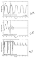
- Fig. 6 is a waveform diagram illustrating measured torque-angle characteristic functions and cogging for a permanent-magnet synchronous motor.
- Fig. 7 is a waveform diagram illustrating initial (poorly) estimated torque-angle characteristic functions for the motor of Fig. 6.
- Fig. 8A is a graphical illustration of self-tuning velocity trajectory tracking control of the permanent-magnet synchronous motor of Fig. 6 using the present invention.
- Fig. 8B is a graphical illustration of tracking error attained by the present invention in following the velocity trajectory of Fig. 8A.
- Fig. 8C is a graphical illustration of the instantaneous power supplied to the motor of Fig. 6 in following the velocity trajectory of Fig. 8A.
- Fig. 9A is a graphical illustration of self-tuning position trajectory tracking control of the permanent-magnet synchronous motor of Fig. 6 using the present invention.
- Fig. 9B is a graphical illustration of tracking error attained by the present invention in following the position trajectory of Fig. 9A.
- Fig. 9C is a graphical illustration of the instantaneous power supplied to the motor of Fig. 6 in following the position trajectory of Fig. 9A.
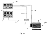
- FIG. 1A illustrates a prototype apparatus which has been constructed to demonstrate the efficacy of the self-tuning method of the present invention.
- Fig. 1A illustrates a prototype apparatus which has been constructed to demonstrate the efficacy of the self-tuning method of the present invention.
- Fig. 1A includes a computer 10 for controlling motor 30 and its load at shaft 28 via amplifier 22, based on the rotor position and velocity as sensed by encoder 26.
- computer 10 is an Intel 80486-based personal computer with a floating point digital signal processor (DSP) card 12, part number 600-01011 from Spectrum Signal Processing, Inc. of Vancouver British Columbia, Canada.
- DSP floating point digital signal processor
- the self-tuning method of the present invention is implemented by the 32 bit floating point DSP processor board 12 which is connected to analog input board 14 and the 1000 line encoder 26.
- Analog input board 14 is a 32-channel board from Spectrum Signal Processing, Inc., part number 600-00257.
- Analog input board 14 is connected to processor board 12 via DSP link 18, a high-speed parallel bus.
- Analog output board 16 is a 16 channel board from Spectrum Signal Processing, Inc., part number 600-00428.
- Fig. 1A Also shown in Fig. 1A is permanent-magnet synchronous motor 30 which may be used to move a load connected to shaft 28 in accordance with a desired position or velocity trajectory.
- Encoder 26 is attached to the back of motor 30 so that the position and velocity of the rotor of motor 30 (connected to shaft 28) may be determined by conventional techniques and supplied to processor board 12 over line 34.
- Power is supplied to motor 30 by a three-phase, power op-amp based linear amplifier 22, with the stator currents of motor 30 being obtained by measuring a voltage drop across current sensors 24, which are generic 1 ohm, 20 watt power resistors connected in series with the stator windings of motor 30.
- Amplifier 22 drives motor 30 over line 42 based on command signals received from analog output board 16 over line 40 and current feedback signals received from current sensors 24 over line 36.
- Fig. 1B illustrates a preferred, low-cost implementation for the self-tuning method of the present invention.
- This arrangement includes a low-cost controller board 43 controlling the motor 30 and its load at shaft 28 via a low-cost pulse-width modulation (PWM) amplifier 44, based on the rotor position and velocity measured with encoder 26.
- the controller board 43 is based on a low-cost, fixed point 16 bit microprocessor, such as the MC68HC16 microcontroller from Motorola.
- Controller board 43 also includes encoder interface circuitry for converting the quadrature encoder signals of line 48, analog to digital conversion circuitry for measurement of the stator current signals of line 47, and digital to analog conversion circuitry for commanding the amplifier 44 over line 45. Based on stator current measurements from current sensors 24 and rotor position and velocity measurements derived from encoder 26, the microprocessor of controller board 43 applies excitation to the motor 30 via the PWM amplifier 44 using lines 45 and 46.
- the amplifier 44 is a low-cost, 3 phase PWM type switching amplifier, based on either a standard inverter configuration or a unipolar H-bridge configuration. Based on input from the controller board 43 via line 45, and measurements of the stator currents from the current sensors 24 via line 47, the amplifier 44 commands the stator voltages of the motor 30 via line 46.
- the motor 30 is a permanent-magnet synchronous motor, which drives the load via shaft 28. Attached to shaft 28 is also encoder 26, which provides for quadrature signals 48 which may be used to measure the position and velocity of shaft 28.
- the current sensors 24 may be generic power resistors, connected in series with the stator windings of the motor 30, or they may be Hall-effect current sensors, or they may be SenseFet-based current sensors.
- Block 51 depicts the initial step of initializing the system wherein the encoder 26 is initialized as well as the parameter estimates for the motor. These initial estimates of the motor's characteristics needn't be particularly accurate because of the self-tuning (self-correcting) nature of the invention. These initial estimates of the motor's characteristics are used in a mathematical model, described in more detail below, to calculate an initial excitation to be applied to the motor to urge the motor toward a desired position and/or velocity trajectory. The initial excitation is then applied to the motor, as per block 52. The response of the motor to the initial excitation is detected by determining the new rotor position, rotor velocity, and the stator currents (block 53).
- This information about how the motor performed in response to the excitation is then used to calculate an updated model of the motor (block 54).
- the updated motor model is used, along with the rotor position and rotor velocity information, to calculate a new excitation to be applied to the motor.
- this new excitation is then applied to the motor and the cycle of observing the motor's performance, updating the motor model, calculating a new excitation, and applying the new excitation repeats over and over (blocks 53 - 56).
- Step 60 begins in step 60 with the initialization of the unknown parameters to some nominal value such as those which may be supplied by manufacturers' data sheets.
- Step 60 also includes the initialization of encoder 26 either using a hardware zero reference or by performing an initialization sequence on the motor. It should be noted that the performance of an initialization sequence on the motor is not required if an absolute position sensor is used as encoder 26.
- the repetitive part of the self-tuning method of the present invention i.e., steps 62, 64, 66, 68, 70, 72, and 74 is entered.
- the first step in this loop involves measuring rotor position, ⁇ [n], via encoder 26 and measuring the stator currents, i[n], via current sensors 24.
- Step 62 may be carried out by any conventional measuring techniques with any necessary conversion so that appropriate measurement units are obtained.
- rotor velocity, ⁇ [n] is computed using, for example, any appropriate numerical differentiator operating on the measured ⁇ [n] from step 62.
- This step typically includes using a low pass filter which attenuates any noise which may result from the numerical differentiation.
- step 66 the known last input u[n-1] the measured i[n] and ⁇ [n] from step 62, and the computed ⁇ [n] from step 64 are used to compute updated electrical parameter estimates, ⁇ e [n+1].
- One of the electrical parameter estimates computed in step 66 is the torque-angle characteristic function.
- a new piecewise-linear (or piecewise-polynomial) approximation of the torque-angle characteristic function of motor 30 is used in accordance with the teachings of the present invention as is more fully discussed below.
- a piecewise approximation for the motor load may be used.
- updated mechanical parameter estimates, ⁇ m [n+1] are computed using the known last input, u[n-1], the measured rotor position, ⁇ [n-1], the computed rotor velocities, ⁇ [n] and ⁇ [n-1], and the estimated electrical parameters, ⁇ e [n].
- step 70 the measured position, ⁇ [n], the computed velocity, ⁇ [n], and the estimated electrical and mechanical parameters, ⁇ e [n+1] and ⁇ m [n+1], respectively, as well as the desired rotor position or velocity, ⁇ d [n] or ⁇ d [n], respectively, are used to compute the new control input, u[n].
- Control is implemented using an error-driven normalized gradient parameter update law based on a discrete-time, reduced-order mathematical model of a permanent-magnet synchronous motor which evolves in the mechanical time-scale which is substantially slower than the electrical time-scale of the motor. This feature of the present invention is also discussed in further detail below.
- step 72 the new control input, u[n], is applied to motor 30 via a digital to analog converter in controller board 43 and amplifier 44.
- ⁇ and ⁇ respectively are the angular rotor position and velocity
- i is an M vector of stator phase currents
- J is the rotor moment of inertia
- ⁇ L ( ⁇ , ⁇ , t ) is the load torque
- K ( ⁇ ) is a vector of torque-angle characteristic functions
- L is a diagonal matrix of stator phase self-inductances
- R is a diagonal matrix of stator phase resistances
- v is a vector of phase input voltages
- the ' denotes algebraic transposition.
- K amp is a diagonal gain matrix and u is an M vector of digital inputs
- K ( ⁇ ) Prior to parameterizing the system, it is first necessary to approximate K ( ⁇ ) with a function that depends on only a finite number of fixed (with respect to ⁇ ) parameters.
- a known prior method for accomplishing this is to approximate K ( ⁇ ) with a truncated Fourier series, with the parameters being the Fourier coefficients.
- This method suffers from several disadvantages.
- some torque-angle characteristics require many terms from the Fourier series for an accurate approximation, leading to a large number of unknown parameters and a high parameter update computational burden.
- Fourier expansions require transcendental function evaluations, which require significant computation.
- any periodic function (with a bounded first derivative) may be approximated to any desired degree of accuracy using the piecewise-linear approximation by simply choosing N s to be large enough. Note that the intervals over which the function is assumed to be affine need not all be of the same length. For simplicity, however, equal length intervals are chosen as shown in Fig. 3.
- Equation 16 the definition in Equation 16 appears computationally complex, the graphical description in Fig. 4 shows that the functions are conceptually simple. It should be further noted that evaluation of a shape function requires only one modulo and one multiply operation (despite the definition in Equation 16, and in contrast to a sin( ⁇ ) call).
- the piecewise-linear approximation of the j th element of K ( ⁇ ) can be written as the linear-in-parameter description where Note that the shape functions basically provide a means of writing K ( ⁇ ) over each interval as a convex combination of the interval endpoint values.
- Equation 17 may require more parameters than a Fourier truncation approximation of similar accuracy. In this case, why would one choose the piecewise-linear formulation over the truncated Fourier series? Besides the aforementioned advantage of not requiring transcendental function calls, there is another significant advantage to the piecewise-linear parameterization which is not readily evident from Equations 17-19.
- Equation 22 the piecewise-linear approximation j ( ⁇ ) may be more simply written as where The simplified formulation of Equation 23 reveals that evaluation of the approximate j ( ⁇ ) requires only 4 multiplies and 2 modulos. It should be noted, however, that the parameter vector is not complete, in the sense that it does not contain all of the parameters necessary to approximate K j ( ⁇ ) for all values of ⁇ . Finally note that because it requires more parameters, the piecewise-linear parameterization will usually require more computer memory than a comparably accurate truncated Fourier series (at least for functions with small higher order harmonics). However, one would expect that accurate piecewise-linear parameterizations would require at most a few hundred parameters, and the memory costs under this assumption are inconsequential.
- Equations 9-11 may now be written as a linear expression of the unknown parameters. It is assumed that the parameters of the piecewise-linear approximation ( ⁇ ), the effective resistances R e , the rotor inertia J and any parameters associated with the load torque ⁇ L ( ⁇ [ n ], ⁇ [ n ], nT ) are all unknown.
- the load torque can be linearly parameterized as where the regressor w ⁇ [ n ] is a function of only the known quantities ⁇ [ n ], ⁇ [ n ] and nT .
- the linear-in-parameter outer-loop output equation is written as where The dependence of y m on the electrical parameters ⁇ will require a nested identifier structure.
- the self-tuning controller may be formulated on the basis of Equations 9-11, 27-29 and 32-35.
- Fig. 5 depicts the permanent-magnet synchronous motor self-tuning controller of the present invention in block diagram form.
- Blocks 80, 82, and 84, marked F m , F ⁇ and F ⁇ , respectively, constitute the digital controller.
- the "Inner Loop Identifier" block 86 takes the current measurement i [ n ], the amplifier input u [ n - 1], and the rotor position and velocity ⁇ [ n ] and ⁇ [ n ] and computes the next electrical parameter estimate ⁇ e [ n + 1] per Equation 47, listed below.
- the "Outer Loop Identifier” block 88 takes the amplifier input u [ n - 1], the rotor position and velocity ⁇ [ n ] and ⁇ [ n ], and the electrical parameter estimate ⁇ e [ n + 1] and computes the next mechanical parameter estimate ⁇ m [ n + 1] per Equation 49, listed below.
- the F m block 80 takes the rotor position and velocity ⁇ [ n ] and ⁇ [ n ], and the desired position ⁇ d [ n ] (for position control) or desired velocity ⁇ d [ n ] (for velocity control), and computes the desired acceleration signal ⁇ d [ n ] per Equations 43-44, listed below.
- the F ⁇ block 82 takes the desired acceleration ⁇ d [ n ], the rotor position and velocity ⁇ [ n ] and ⁇ [ n ] and the mechanical parameter estimate ⁇ m [ n + 1] and computes the desired torque ⁇ d [ n ] per Equations 39-40, listed below (where ⁇ replaced by ⁇ m [ n + 1]).
- the F ⁇ block 84 takes the desired torque ⁇ d [ n ], the rotor position and velocity ⁇ [ n ] and ⁇ [ n ] and the electrical parameter estimate ⁇ e [ n + 1], and computes the amplifier input command u [ n ] per Equations 36-37, listed below (where ⁇ is replaced by ⁇ e [ n + 1]).
- the K amp block 90 which is internal to the power amplifier, takes the analog current measurement i ( t ) and the amplifier input u [ n ], and outputs the voltage u [ n ] - K amp i ( t ).
- the motion tracking controller that determines the ⁇ d [ n ] necessary to achieve either velocity or position trajectory tracking may now be formulated.
- the position trajectory may be arbitrarily specified.
- the choice of ⁇ d [ n ] given by Equation 43 gives mechanical dynamics Choosing K ⁇ ⁇ 0 and T 2 K ⁇ - 1 ⁇ K ⁇ ⁇ TK ⁇ + 1, if ⁇ d [ n ] is appropriately bounded and if for n ⁇ 0, then the position tracking error decays to an O ( L + T 2) neighborhood of zero.
- Equation 47 requires only about 15 flops/phase, regardless of the number of segments N s . This means that the piecewise-linear parameterization requires less computation than a two parameter (magnitude and phase) Fourier truncation. Thus, for any torque-angle characteristic which has even a single harmonic, the new technique consistently gives greater accuracy than the truncated Fourier series of comparable update computational complexity.
- Equation 32 Using the robust normalized gradient update law with the outer-loop output equation, Equation 32, gives the mechanical parameter estimate update law where ⁇ m is a diagonal matrix of design gains, ⁇ m and ⁇ m are design parameters and the dead-zone on the error term is again used for improved robustness.
- the nominal parameter values for the motor 30 (unloaded) are given below.
- the actual torque-angle characteristic functions, along with the actual cogging, are shown in Fig. 6. These plots were determined by measurements with a standard torque sensor. Note that the torque-angle characteristics are not close to sinusoidal, and as such, cannot be accurately approximated with a truncated Fourier series unless several terms are included. Thus, the motor chosen for the purpose of demonstrating the present invention highlights the advantages of the new piecewise-linear approximation.
- the assumed initial torque-angle characteristic functions are as shown in Fig. 7. Note that not only are the amplitude and "shape" of the initial estimates in error, but more importantly, the fundamental components of the assumed torque-angle curves are out of phase (by 0.225 rad) with their actual counterparts of Fig. 6. Such phase errors may be the consequence of a misalignment between the position sensor and the torque-angle characteristic functions. This means that the linearizing control will have large errors, resulting in very poor performance in the absence of adaptation (self-tuning).
- the identifier gains used are given below: Parameter Value ⁇ e diag ⁇ 0.025,0.005,0.005 ⁇ ⁇ e 0.2 ⁇ e 1.0 ⁇ m diag ⁇ 0.02,0.02,1.0,1.0 ⁇ ⁇ m 0.01 ⁇ m 0.0005 These values were determined by tuning the controller over several runs. It is emphasized, however, that the performance of the scheme is not unreasonably sensitive to these values, so one can expect performance similar to that described below using a wide range of gains.
Landscapes
- Engineering & Computer Science (AREA)
- Power Engineering (AREA)
- Control Of Motors That Do Not Use Commutators (AREA)
- Control Of Ac Motors In General (AREA)
Applications Claiming Priority (2)
| Application Number | Priority Date | Filing Date | Title |
|---|---|---|---|
| US10500393A | 1993-08-11 | 1993-08-11 | |
| US105003 | 1993-08-11 |
Publications (2)
| Publication Number | Publication Date |
|---|---|
| EP0638988A2 true EP0638988A2 (de) | 1995-02-15 |
| EP0638988A3 EP0638988A3 (de) | 1995-03-08 |
Family
ID=22303546
Family Applications (1)
| Application Number | Title | Priority Date | Filing Date |
|---|---|---|---|
| EP94202299A Withdrawn EP0638988A3 (de) | 1993-08-11 | 1994-08-10 | Selbsteinstellender Folgeregler für Permanentmagnetsynchronmotoren |
Country Status (4)
| Country | Link |
|---|---|
| US (1) | US5834918A (de) |
| EP (1) | EP0638988A3 (de) |
| JP (1) | JPH07177782A (de) |
| CA (1) | CA2129761A1 (de) |
Cited By (7)
| Publication number | Priority date | Publication date | Assignee | Title |
|---|---|---|---|---|
| EP0748038A3 (de) * | 1995-06-05 | 1998-04-22 | Kollmorgen Corporation | System und Verfahren zur Steuerung von bürstenlosen Permanentmagnetmotoren |
| WO1998047806A3 (en) * | 1997-04-04 | 1999-01-21 | Kone Corp | Procedure for determining the parameters for an electric drive controlling a synchronous elevator motor with permanent magnets |
| DE19735581A1 (de) * | 1997-08-16 | 1999-02-18 | Schlafhorst & Co W | Spultrommelantrieb einer Kreuzspulen herstellenden Textilmaschine |
| WO1999028229A3 (en) * | 1997-11-13 | 1999-07-22 | Kone Corp | Elevator control system for synchronous motor |
| EP1034459A4 (de) * | 1997-11-26 | 2000-11-08 | Voyan Technology | Signalverarbeitungs- und regelungssystem auf mehreren ebenen |
| WO2003011731A1 (en) * | 2001-08-01 | 2003-02-13 | Kone Corporation | Method for correcting speed feedback in a permanent-magnet motor |
| WO2004066482A3 (en) * | 2003-01-14 | 2005-03-24 | Christopher P Cullen | Electric motor controller |
Families Citing this family (33)
| Publication number | Priority date | Publication date | Assignee | Title |
|---|---|---|---|---|
| US6017143A (en) * | 1996-03-28 | 2000-01-25 | Rosemount Inc. | Device in a process system for detecting events |
| DE19703248B4 (de) * | 1997-01-29 | 2006-01-26 | Siemens Ag | Verfahren und Vorrichtung zur Bestimmung einer Rotorwinkelgeschwindigkeit einer geberlosen, feldorientiert betriebenen Drehfeldmaschine |
| US6064170A (en) * | 1998-08-31 | 2000-05-16 | Eastman Kodak Company | Method of controlling a printhead movement based on a screw pitch to minimize swath-to-swath error in an image processing apparatus |
| US7076340B1 (en) * | 1999-05-28 | 2006-07-11 | Kabushiki Kaisha Yaskawa Denki | Method of controlling speed of synchronous motor, and method of identifying constant of synchronous motor |
| AU2001249563A1 (en) * | 2000-03-29 | 2001-10-08 | Suresh Gopalakrishnan | System and method for inductance based position encoding for sensorless srm drives |
| US7003380B2 (en) * | 2001-02-27 | 2006-02-21 | Sikorsky Aircraft Corporation | System for computationally efficient adaptation of active control of sound or vibration |
| GB0109643D0 (en) * | 2001-04-19 | 2001-06-13 | Isis Innovation | System and method for monitoring and control |
| DE10392179B4 (de) * | 2002-01-14 | 2009-10-15 | Siemens Vdo Automotive Corp., Auburn Hills | Reifendrucküberwachungssystem mit einer Adaption beim Wechsel vom stehenden zum fahrenden Zustand des Fahrzeugs |
| US6756757B2 (en) * | 2002-05-21 | 2004-06-29 | Emerson Electric Company | Control system and method for a rotating electromagnetic machine |
| US6727668B1 (en) * | 2002-06-19 | 2004-04-27 | Wavecrest Laboratories, Llc | Precision brushless motor control utilizing independent phase parameters |
| US6794839B1 (en) * | 2002-11-08 | 2004-09-21 | Wavecrest Laboratories, Llc | Precision motor control with selective current waveform profiles in separate stator core segments |
| US6919700B2 (en) * | 2003-01-29 | 2005-07-19 | Wavecrest Laboratories, Llc | Adaptive control of motor stator current waveform profiles |
| US6940242B1 (en) * | 2003-01-29 | 2005-09-06 | Wavecrest Laboratories, Llc | Motor control system for dynamically changing motor energization current waveform profiles |
| US7135830B2 (en) * | 2003-09-30 | 2006-11-14 | Reliance Electric Technologies, Llc | System and method for identifying operational parameters of a motor |
| US7184902B2 (en) * | 2003-09-30 | 2007-02-27 | Reliance Electric Technologies, Llc | Motor parameter estimation method and apparatus |
| WO2005067137A1 (ja) * | 2004-01-07 | 2005-07-21 | Mitsubishi Denki Kabushiki Kaisha | モータ制御装置 |
| TWI302233B (en) * | 2005-08-19 | 2008-10-21 | Delta Electronics Inc | Method for estimating load inertia and a system for controlling motor speed by using inverse model |
| DE102006055917B4 (de) * | 2006-11-27 | 2014-11-27 | Kuka Roboter Gmbh | Industrieroboter und Verfahren zum Erkennen eines ungenau parametrierten Robotermodells |
| TWI384748B (zh) * | 2009-04-03 | 2013-02-01 | Anpec Electronics Corp | 用於一馬達之驅動方法及其相關驅動裝置 |
| KR101470025B1 (ko) * | 2009-07-06 | 2014-12-15 | 현대자동차주식회사 | 비상 운전용 고효율 영구자석 동기모터의 각도위치 센서리스 제어 방법 |
| US8214063B2 (en) * | 2009-09-29 | 2012-07-03 | Kollmorgen Corporation | Auto-tune of a control system based on frequency response |
| TWI404942B (zh) * | 2009-12-10 | 2013-08-11 | Ind Tech Res Inst | 扭轉共振頻率測量裝置及方法 |
| US20110257768A1 (en) * | 2010-03-26 | 2011-10-20 | International Business Machines Corporation | Control of a dynamic system cross reference to related application |
| US8941342B2 (en) * | 2011-08-26 | 2015-01-27 | Mitsubishi Electric Corp. | Integrated servo system |
| WO2013111968A1 (ko) * | 2012-01-25 | 2013-08-01 | Park In Gyu | 다상 전 브리지 전압원 인버터의 전류 제어 펄스 폭 변조 방법 |
| US10234165B2 (en) * | 2012-07-21 | 2019-03-19 | Zhongshan Broad-Ocean Motor Co., Ltd. | HVAC control system for household central air conditioning |
| JP6867503B2 (ja) * | 2017-09-26 | 2021-04-28 | 株式会社日立製作所 | 機器制御システム |
| CN109391200B (zh) * | 2018-10-15 | 2020-08-11 | 贵州航天林泉电机有限公司 | 一种同步电机参数自辨识整定方法 |
| CN109143869B (zh) * | 2018-10-16 | 2021-07-06 | 沈阳工业大学 | 一种h型平台的递归小波神经网络补偿器的同步控制系统 |
| CN115208248B (zh) * | 2022-07-27 | 2025-02-18 | 山东交通学院 | 基于数据驱动二阶积分终端滑模的直流有刷电机控制方法 |
| CN117653895A (zh) * | 2024-01-15 | 2024-03-08 | 微创外科医疗科技(上海)有限公司 | 转子悬浮控制方法、磁悬浮心室辅助系统和可读存储介质 |
| CN118551150B (zh) * | 2024-07-29 | 2024-11-05 | 深圳市百思泰科技有限公司 | 基于扭力测试的扭力补偿方法、装置、设备及存储介质 |
| CN121055814B (zh) * | 2025-11-05 | 2026-02-17 | 南京工程学院 | 大尺寸超薄光伏硅片多线切割机四主轴速度控制方法及系统 |
Family Cites Families (15)
| Publication number | Priority date | Publication date | Assignee | Title |
|---|---|---|---|---|
| US4025837A (en) * | 1975-06-30 | 1977-05-24 | International Business Machines Corporation | Adaptive control circuit for a stepping motor |
| US4129813A (en) * | 1977-07-26 | 1978-12-12 | The Singer Company | Method and apparatus for adaptive control of a stepper motor |
| US4369400A (en) * | 1980-09-02 | 1983-01-18 | The Singer Company | Servo control system |
| US4481457A (en) * | 1981-03-06 | 1984-11-06 | General Electric Company | Method for providing adaptive control of variable speed AC motor drives |
| US4670698A (en) * | 1983-12-02 | 1987-06-02 | Imec Corporation | Adaptive induction motor controller |
| US4701839A (en) * | 1984-11-09 | 1987-10-20 | International Cybernetic Corporation | Sampled data servo control system with field orientation |
| US4609855A (en) * | 1984-11-09 | 1986-09-02 | Motorola, Inc. | Adaptive servomotor control |
| US4733149A (en) * | 1985-05-31 | 1988-03-22 | Kollmorgen Technologies Corporation | Adaptive control system |
| JPH0729252B2 (ja) * | 1986-01-17 | 1995-04-05 | 東芝機械株式会社 | 主軸位置決め装置 |
| JPS6447290A (en) * | 1987-08-18 | 1989-02-21 | Toshiba Corp | Motor speed controller |
| US5038090A (en) * | 1988-10-05 | 1991-08-06 | Toyota Jidosha Kabushiki Kaisha | Servo motor control apparatus |
| US4862054A (en) * | 1988-10-31 | 1989-08-29 | Westinghouse Electric Corp. | Tacho-less vector control adaptive system for motor drive |
| US5124625A (en) * | 1990-05-11 | 1992-06-23 | Matsushita Electric Industrial Co., Ltd. | Position control system |
| JP3063121B2 (ja) * | 1990-07-19 | 2000-07-12 | 株式会社安川電機 | トルクリップルの低減方法 |
| US5089757A (en) * | 1991-03-15 | 1992-02-18 | Maxtor Corporation | Synchronous digital detection of position error signal |
-
1994
- 1994-08-09 CA CA002129761A patent/CA2129761A1/en not_active Abandoned
- 1994-08-10 EP EP94202299A patent/EP0638988A3/de not_active Withdrawn
- 1994-08-11 JP JP6189632A patent/JPH07177782A/ja active Pending
-
1996
- 1996-04-01 US US08/627,910 patent/US5834918A/en not_active Expired - Fee Related
Cited By (12)
| Publication number | Priority date | Publication date | Assignee | Title |
|---|---|---|---|---|
| EP0748038A3 (de) * | 1995-06-05 | 1998-04-22 | Kollmorgen Corporation | System und Verfahren zur Steuerung von bürstenlosen Permanentmagnetmotoren |
| WO1998047806A3 (en) * | 1997-04-04 | 1999-01-21 | Kone Corp | Procedure for determining the parameters for an electric drive controlling a synchronous elevator motor with permanent magnets |
| US6285961B1 (en) | 1997-04-04 | 2001-09-04 | Kone Corporation | Procedure for determining the parameters for an electric drive controlling a synchronous elevator motor with permanent magnets |
| DE19735581A1 (de) * | 1997-08-16 | 1999-02-18 | Schlafhorst & Co W | Spultrommelantrieb einer Kreuzspulen herstellenden Textilmaschine |
| US6002230A (en) * | 1997-08-16 | 1999-12-14 | W Schlafhorst Ag & Co. | Winding drum drive of a cheese-producing textile machine |
| WO1999028229A3 (en) * | 1997-11-13 | 1999-07-22 | Kone Corp | Elevator control system for synchronous motor |
| EP1034459A4 (de) * | 1997-11-26 | 2000-11-08 | Voyan Technology | Signalverarbeitungs- und regelungssystem auf mehreren ebenen |
| WO2003011731A1 (en) * | 2001-08-01 | 2003-02-13 | Kone Corporation | Method for correcting speed feedback in a permanent-magnet motor |
| US7339343B2 (en) | 2001-08-01 | 2008-03-04 | Kone Corporation | Method for correcting speed feedback in a motor |
| WO2004066482A3 (en) * | 2003-01-14 | 2005-03-24 | Christopher P Cullen | Electric motor controller |
| US7437201B2 (en) | 2003-01-14 | 2008-10-14 | Cullen Christopher P | Electric motor controller |
| US7606624B2 (en) | 2003-01-14 | 2009-10-20 | Cullen Christopher P | Self-commissioning electronic motor controller determination |
Also Published As
| Publication number | Publication date |
|---|---|
| CA2129761A1 (en) | 1995-02-12 |
| JPH07177782A (ja) | 1995-07-14 |
| US5834918A (en) | 1998-11-10 |
| EP0638988A3 (de) | 1995-03-08 |
Similar Documents
| Publication | Publication Date | Title |
|---|---|---|
| EP0638988A2 (de) | Selbsteinstellender Folgeregler für Permanentmagnetsynchronmotoren | |
| Taylor | Nonlinear control of electric machines: An overview | |
| Apte et al. | Disturbance observer based speed control of PMSM using fractional order PI controller | |
| Mir et al. | Switched reluctance motor modeling with on-line parameter identification | |
| Jung et al. | Diminution of current-measurement error for vector-controlled AC motor drives | |
| US5296794A (en) | State observer for the permanent-magnet synchronous motor | |
| CN102326329B (zh) | 交流电机的控制装置及交流电机驱动系统 | |
| Bowes et al. | New natural observer applied to speed-sensorless DC servo and induction motors | |
| EP0535280B1 (de) | Flussrückkopplungssystem | |
| CN112271972A (zh) | 带有电流误差校正的永磁同步电机直接转矩控制方法 | |
| Hong et al. | A novel inertia identification method for speed control of electric machine | |
| CN114915226A (zh) | 一种超局部模型的永磁同步电机预测控制方法及系统 | |
| EP0104909B1 (de) | Servomotorregelverfahren und dessen Gerät | |
| Barambones Caramazana et al. | Sliding mode position control for real-time control of induction motors | |
| Aghili | Adaptive reshaping of excitation currents for accurate torque control of brushless motors | |
| Mattohti et al. | A Field-Oriented Control algorithm with Multi-Sensor Data Fusion for permanent magnet synchronous motor: Design, analysis and experiments | |
| Solodkiy et al. | Sensorless vector control of asynchronous machine based on reduced order Kalman filter | |
| CN115051601B (zh) | 变速旋转直流电机伺服系统的扰动补偿和跟踪控制方法 | |
| Salvatore et al. | LKF based robust control of electrical servodrives | |
| Seki et al. | Robust positioning control using α-β stationary frame current controller and disturbance torque hybrid observer | |
| Dell'Aquila et al. | Kalman filter estimators applied to robust control of induction motor drives | |
| Von Westerholt et al. | Extended state estimation of nonlinear modeled induction machines | |
| Romanov et al. | A comparison of hardware implementations of FOC controllers for asynchronous motor drive based on FPGA | |
| Kim et al. | Full digital controller of permanent magnet AC servo motor for industrial robot and CNC machine tool | |
| Lim et al. | Observers for sensorless control of permanent magnet synchronous motor drive |
Legal Events
| Date | Code | Title | Description |
|---|---|---|---|
| PUAI | Public reference made under article 153(3) epc to a published international application that has entered the european phase |
Free format text: ORIGINAL CODE: 0009012 |
|
| PUAL | Search report despatched |
Free format text: ORIGINAL CODE: 0009013 |
|
| AK | Designated contracting states |
Kind code of ref document: A2 Designated state(s): DE FR GB |
|
| AK | Designated contracting states |
Kind code of ref document: A3 Designated state(s): DE FR GB |
|
| RIN1 | Information on inventor provided before grant (corrected) |
Inventor name: SHOUSE,KENNETH R. Inventor name: TAYLOR, DAVID G. |
|
| 17P | Request for examination filed |
Effective date: 19950626 |
|
| 17Q | First examination report despatched |
Effective date: 19960704 |
|
| GRAG | Despatch of communication of intention to grant |
Free format text: ORIGINAL CODE: EPIDOS AGRA |
|
| GRAG | Despatch of communication of intention to grant |
Free format text: ORIGINAL CODE: EPIDOS AGRA |
|
| GRAG | Despatch of communication of intention to grant |
Free format text: ORIGINAL CODE: EPIDOS AGRA |
|
| GRAH | Despatch of communication of intention to grant a patent |
Free format text: ORIGINAL CODE: EPIDOS IGRA |
|
| STAA | Information on the status of an ep patent application or granted ep patent |
Free format text: STATUS: THE APPLICATION IS DEEMED TO BE WITHDRAWN |
|
| 18D | Application deemed to be withdrawn |
Effective date: 19971204 |