EP0639916B1 - Verfahren und System zum Verbinden von mit mehreren Protokollen versehender Endstellen - Google Patents
Verfahren und System zum Verbinden von mit mehreren Protokollen versehender Endstellen Download PDFInfo
- Publication number
- EP0639916B1 EP0639916B1 EP94480055A EP94480055A EP0639916B1 EP 0639916 B1 EP0639916 B1 EP 0639916B1 EP 94480055 A EP94480055 A EP 94480055A EP 94480055 A EP94480055 A EP 94480055A EP 0639916 B1 EP0639916 B1 EP 0639916B1
- Authority
- EP
- European Patent Office
- Prior art keywords
- network equipment
- workstation
- characteristic
- protocol type
- protocol
- Prior art date
- Legal status (The legal status is an assumption and is not a legal conclusion. Google has not performed a legal analysis and makes no representation as to the accuracy of the status listed.)
- Expired - Lifetime
Links
Images



Classifications
-
- H—ELECTRICITY
- H04—ELECTRIC COMMUNICATION TECHNIQUE
- H04L—TRANSMISSION OF DIGITAL INFORMATION, e.g. TELEGRAPHIC COMMUNICATION
- H04L9/00—Cryptographic mechanisms or cryptographic arrangements for secret or secure communications; Network security protocols
- H04L9/40—Network security protocols
Definitions
- the present invention relates to the interconnection of digital communications networks and, more particularly, to a system for automatically connecting a network workstation of a particular protocol type with network equipment of the same protocol type.
- Rapid changes in digital communications networks have generated a multiplicity of network types, many of which co-exist. For example, many times both host-centric and distributed communications networks are used within a business environment. Each type of network has a useful function necessary in many business environments.
- a host-centric communications network is one in which all information transferred between connected devices is managed by a central host processor unit.
- An example of a host-centric network is one comprising a mainframe from International Business Machines (IBM) « (such as a System/390 «) having a plurality of display terminals (such as IBM 3270 Information Display Systems) connected via a control unit (such as an IBM 3174 terminal controller).
- IBM International Business Machines
- a control unit such as an IBM 3174 terminal controller
- a distributed communications network is one in which information is transferred between devices attached to the network without the intervention of a central host processor.
- These distributed networks can be constructed from local area network technologies, such as Ethernet (as defined by the IEEE 802.3 standard) or token ring (IEEE 802.5 standard).
- a networking protocol may define the manner in which the data is framed or in which errors are checked.
- a networking protocol normally defines the physical interface, or the actual physical connectivity and medium used by the network. This physical interface definition is analogous to the physical layer of the seven-layer Open Systems Interface (OSI) reference model. Examples are the use of unshielded twisted pair, coaxial or fiber optic cabling for the transmission of bit streams across the particular physical medium.
- OSI Open Systems Interface
- Contemporary installation of wiring media utilizes a single multiprotocol cable that is electrically compatible with several network types.
- data-grade, shielded-twisted pair wiring is being used to transmit data conforming to the token ring, Ethernet 10baseT, and RS232 serial protocols.
- Such a multiprotocol medium eliminates the need to wire facilities differently for each unique network.
- such a wiring system permits a device, equipped with one of many interfaces, connected to a nearby port wired with the single multiprotocol medium to communicate with the appropriate controller, concentrator, multiplexor, or hub connected at the other end to complete the network connection.
- the use of such multiprotocol medium permits a device to be moved to another office, for instance, no matter which physical interface the device has if the office has a multiprotocol-wired port.
- the system 10 comprises a wiring closet 12 for providing a centralized location for the network wiring to terminate, and two offices, Office 14 and Office 16, each having a wall port, Wall Port 18 and Wall Port 20.
- Office 14 has a Terminal Workstation 22 connected to Wall Port 18 while Office 16 has a Token Ring Workstation 24 connected to Wall Port 20.
- a Patch Panel 26 connects Cabling 28 from Wall Port 18 and Cabling 30 from Wall Port 20 to a Terminal Controller 32 and a Token Ring Multistation Access Unit (MAU) 34 via Cabling 36 and Cabling 38, respectively.
- Terminal Controller 32 and Token Ring MAU 34 are respectively connected to their corresponding networks via Cabling 40 (to/from Mainframe) and Cabling 42 (to and from token ring network).
- Token Ring Workstation 24 may be moved to Office 14 and connected to Wall Port 18 as Cabling 28 supports the token ring physical protocol.
- Terminal Workstation 22 may be moved to Office 16 and connected to Wall Port 20.
- Cabling 36 and Cabling 38 must be swapped at Patch Panel 26, i.e., Cabling 36 must be disconnected from Patch Panel Port 46 and connected to Patch Panel Port 48 and vice versa with Cabling 38. This process is a manual one and requires that a technician, first, find the cable associated with the newly attached device, then disconnect the cable from its current point of attachment, and finally, reconnect it to a designated port on equipment that is compatible with the device being attached.
- IHUBS intelligent hubs
- Terminal Workstation 22 and Token Ring Workstation 24 were to exchange offices, Terminal Workstation 22 moving to Office 16 and connecting to Wall Port 20 and Token Ring Workstation 24 moving to Office 14 and connecting to Wall Port 18, Cabling 28 and Cabling 30 would have to be manually exchanged.
- the IHUB 50 is only reconfigurable using Network Manager 52 if the workstations are of the same protocol type and are connected to the same blade or different blades (if an additional bridging blade were available and installed).
- Document US 5,086.426 discloses a system that automatically connects secondary LANs with primary LANs via a plurality of bridges.
- the used protocols of the secondary LANs are detected by protocol processing on the basis of the identifier representative of the type of the secondary LANs. According to the protocol identified, the bridges establish connections between the LANs.
- a network port configurator device for automatically configuring a system having network workstations and corresponding network equipment of various physical protocols.
- the network port configurator comprises a plurality of input and output ports for receiving physical wiring to which the workstations and network equipment are attached.
- Detection circuitry attached to the input and output ports determine the physical protocol of the attached workstations and network equipment by determining a characteristic of the attached equipment. Examples of an identifying characteristic include a characteristic impedance, a characteristic voltage, and a characteristic cable identification of the workstation.
- Logic circuitry uses this information to control a circuit switching mechanism that connects the input ports to the output ports.
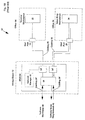
- FIG 2 illustrates a facility 50, similar to the facility shown in Figures 1A and 1B, but having the network port configurator 54 of the present invention installed therein.
- Facility 50 comprises offices 14 and 16 having Terminal Workstation 22 and Token Ring Workstation 24, respectively.
- Facility 50 further has a Wiring Closet 52 connected to Offices 14 and 16 via multiprotocol Cabling 28 and 30, respectively.
- Wiring Closet 52 has a Terminal Network Controller 32 for communicating with the Terminal Workstation 22 and a Token Ring Multistation Access Unit (MAU) 34 for communicating with the Token Ring Workstation 24.
- Terminal Network Controller 32 and Token Ring MAU 34 are connected to the Network Port Configurator 54 of the present invention via Cabling 36 and 38, respectively.
- Terminal Network Controller 32 and Token Ring MAU 34 are connected to, respectively, a mainframe and a token ring network via Cabling 40 (to/from mainframe) and Cabling 42 (to/from token ring network).
- the Network Port Configurator 54 of the present invention automatically connects a network workstation (i.e., Terminal Workstation 22 and Token Ring Workstation 24) with its corresponding network equipment (Terminal Network Controller 32 and Token Ring MAU 34) based upon physical interface protocol of the network workstation and corresponding network equipment. For instance, where Terminal Workstation 22 is disconnected from Wall Port 18 and is moved to Office 16 and connected to Wall Port 20, the Network Port Configurator 54 senses that Terminal Workstation 22 is connected at its Port 62 and automatically establishes a connection between Port 62 and Port 56. The Network Port Configurator 54 accomplishes this by detecting and determining a characteristic of the attached network workstations at Ports 60, 62.
- the Network Port Configurator is able to determine which type of workstation is attached thereto. Similarly, each type of network equipment has a unique characteristic and, therefore, can be distinguished by the Network Port Configurator 54 from other types of network equipment. It is in this manner that the Network Port Configurator of the present invention is able to automatically reconfigure itself so that the network workstations are connected to their corresponding network equipment even where the network workstation is disconnected from its original location and reconnected elsewhere. This is accomplished without any manual intervention.
- the detectable unique characteristic of the various workstations can vary, depending upon the network protocol type.
- the characteristic impedances of a token ring workstation, an Ethernet workstation and a terminal workstation are three distinct and detectable impedances.
- the Network Port Configurator may determine which type it is in order to connect it to its corresponding network equipment.
- FIG. 3A Schematic diagrams of the characteristic impedance of a token ring, a 10baseT Ethernet and a terminal workstation are shown in Figures 3A, 3B and 3C.
- the characteristic impedance of a terminal workstation such as a 3270-type workstation
- Zu the characteristic impedance of a terminal workstation
- Connector 51a uses only wires R and G.
- the impedance between these two wires is the transformer impedance of transformer T1.
- the overall characteristic impedance of the 3270-type terminal is Zu.
- Figure 3B illustrates the characteristic impedance of a token ring workstation.
- the characteristic impedance of this workstation is Zv.
- the Connector 51b of the token ring workstation uses all four wires R, G, O, and B and has transformers T2 and T3 connected therebetween.
- the token ring workstation further has a Signal Circuit 53 connected between R/O and G/B.
- the overall characteristic impedance of the token ring workstation is Zv.
- FIG 3C illustrates the characteristic impedance of an Ethernet 10baseT workstation.
- the characteristic impedance of this workstation is Zw.
- the Connector 51c of the Ethernet 10baseT workstation uses all four wires R, G, O, and B and has transformers T4 and T5 connected therebetween.
- the overall characteristic impedance of the Ethernet 10baseT workstation is Zw.
- the Network Port Configurator of the present invention merely determines the characteristic impedance of the attached device in order to determine which particular device is attached to each particular port.
- Characteristic impedance is shown as but one example of a characteristic by which workstations may be distinguished. Other examples include characteristic voltage levels and cable identifications.
- Network Port Configurator 54 comprises a plurality of Network Port Configurator (NPC) Ports 64, 66, NPC Ports 64 for being connected to I/O Ports 61 (for network equipment) and NPC Ports 66 for being connected to I/O Ports 63 (for network workstations).
- NPC Network Port Configurator
- I/O Ports 61, 63 are connected to the Network Port Configurator 54 by multiprotocol cabling 57, 59.
- a Switch 68 Connected between NPC Ports 64, 66 via cabling 65, 67, respectively, is a Switch 68.
- Switch 68 can be any type of switch which is capable of switching any of the NPC Ports 66 to any of the NPC Ports 64, such as a cross-bar switch. Switch 68 is responsive to control signals transmitted by Configuration (Config.) Logic 70 and conveyed by cabling 72. Config. Logic 70 is further connected to Detection Circuitry 74 via cabling 76. Both Config. Logic 70 and Detection Circuitry 74 are under the control of Program Control 78 via cabling 80. Detection Circuitry 74 is connected to each of the NPC Ports 66 via cabling 82.
- Configuration Configuration
- Config. Logic 70 is further connected to Detection Circuitry 74 via cabling 76. Both Config. Logic 70 and Detection Circuitry 74 are under the control of Program Control 78 via cabling 80. Detection Circuitry 74 is connected to each of the NPC Ports 66 via cabling 82.
- the Network Port Configurator 54 operates as follows. I/O Ports 63 are located in various offices throughout a facility operating a number of different network protocols, such as token ring networks, Ethernet networks, and 3270-type networks. Connected to the I/O Ports 63 are network workstations for communicating on the various networks. Examples of such network workstations are token ring workstations, Ethernet workstations and 3270 terminals. On the other side of the Network Port Configurator 54 are connected the network equipment to I/O Ports 61. Examples of network equipment are a token ring multistation access unit (MAU), an Ethernet concentrator, and a 3174 terminal controller. The network workstations are connected to the corresponding network equipment through Switch 68. Config.
- MAU token ring multistation access unit
- Ethernet concentrator an Ethernet concentrator
- 3174 terminal controller a 3174 terminal controller
- Logic 70 which consists of logic circuitry and switch drivers, generates and transmits control signals to the Switch 68 for setting the Switch in the proper configuration, i.e., so that network workstations communicate with their respective and corresponding network equipment. Config. Logic 70 generates these control signals based upon signals it receives from Detection Circuitry 74 and Program Control 78.
- Detection Circuitry 74 which is connected to each of NPC Ports 66, contains circuitry for detecting and determining the particular characteristic of the network workstations (such as characteristic impedance) connected to the I/O Ports 63. Based upon the characteristic of the respective network workstations (and further based upon the Program Control 78), the Detection Circuitry transmits signals to the Config. Logic 70 so that Switch 68 may be configured properly.
- the Detection Circuitry 74 can determine which type of network workstation is connected to the NPC Port 66. The Detection Circuitry 74 forwards this information, i.e., which type of workstation is connected to which NPC Port 66, to Config. Logic 70. Through Program Control 78, Config. Logic 70 knows which types of network equipment are connected to which NPC Ports 64. By knowing which type of network workstation is attached to which NPC Port 66, the Config. Logic 70 is able to transmit the proper control signals to Switch 68 so that the Switch 68 is properly configured, i.e., the network workstations are connected to their corresponding network equipment.
- Detection Circuitry 74 may be connected to NPC Ports 64, as shown by dashed lines 67a. (For clarity, only one dashed line 67a is shown. Not shown are the other dashed lines between the remaining NPC Ports 64 and the detection Circuit 74.) In this case, Detection Circuitry 74 is able to detect a characteristic of the attached network equipment, in addition to being able to detect a characteristic of the network workstations. Because the various types of network equipment have unique characteristics (as do the workstations), the Network Port Configurator of the present invention is able to distinguish them and automatically configure itself so that the network workstations are properly connected with their corresponding network equipment.
- the method and system of the present invention allows network workstations connected to the system to be disconnected, moved and reconnected to another port of the system and be automatically connected to its corresponding network equipment for communication. This is accomplished through the unique utilization of a detection circuit which detects a characteristic of the attached workstations, such as characteristic impedance, so that the system may determine the type of network. It is in this manner that the workstation may be automatically connected to its corresponding network equipment without manual intervention. While the invention has been particularly shown and described with reference to preferred embodiments thereof, it will be understood by those skilled in the art that various other changes in form and detail may be made without departing from the scope of the invention.
Landscapes
- Engineering & Computer Science (AREA)
- Computer Security & Cryptography (AREA)
- Computer Networks & Wireless Communication (AREA)
- Signal Processing (AREA)
- Communication Control (AREA)
- Computer And Data Communications (AREA)
Claims (17)
- Ein System zur Verwendung mit einer Vielzahl an Netzwerk- Workstations (22, 24) sowie einer Vielzahl an Netzwerkausstattungen (54), wobei jede Workstation (22, 24) und jede Netzwerkausstattung (54) einen Protokolltyp aus einem Satz mit verschiedenen Protokolltypen verwendet und das genannte System eine Workstation eines bestimmten Protokolltyps automatisch mit der Netzwerkausstattung des gleichen Protokolltyps verbindet und wobei jede Workstation eines bestimmten Protokolltyps über eine eindeutige physikalische Eigenschaft im Vergleich zu Workstations anderer Protokolltypen (3A, 3B, 3C) verfügt, wobei das System Folgendes umfasst:Eine Vielzahl an Workstation-Anschlüssen zur Verbindung mit einer oder mehreren Workstations (63),eine Vielzahl an Netzwerkausstattungsanschlüssen zum Verbinden mit einer oder mehreren Netzwerkausstattungen (64), wobei mindestens eine der genannten Netzwerkausstattungen vom gleichen Protokolltyp ist wie die genannten Workstations,ein Mittel, angeschlossen an die genannten Workstation-Anschlüsse (63) zum Erkennen des Protokolltyps jeder der Workstations, die mit den genannten Workstation-Anschlüssen (63) verbunden sind, durch Erkennen der genannten eindeutigen physikalischen Eigenschaft der genannten Workstation, wobei das genannte Mittel zum Erkennen des Protokolls (74) eine Ausgabe mit der Angabe für jeden genannten Protokolltyp (3A, 3B, 3C) generiert, undein Mittel, zwischen die genannten Workstation-Anschlüsse (63) und die genannten Netzwerkausstattungs-Anschlüsse (64) geschaltet, zum Herstellen von Verbindungen zwischen den genannten Workstation-Anschlüssen (63) und den genannten Netzwerkausstattungs-Anschlüssen (64), wobei das genannte Mittel zum Herstellen von Verbindungen auf die genannte Ausgabe des Mittels zum Bestimmen des Protokolltyps reagiert.
- Das System nach Anspruch 1, wobei es sich bei der genannten eindeutigen Eigenschaft um die Eigenschaft Impedanz handelt und das genannte Mittel zum Bestimmen des Protokolls ein Mittel zum Erkennen der Impedanz umfasst, um die Eigenschaft Impedanz der genannten Workstations zu erkennen.
- Das System nach Anspruch 1, wobei es sich bei der genannten eindeutigen physikalischen Eigenschaft um die Eigenschaft Spannung handelt und das genannte Mittel zum Bestimmen des Protokolls ein Mittel zum Erkennen der Spannung umfasst, um die Eigenschaft Spannung der genannten Workstations zu erkennen.
- Das System nach Anspruch 1, wobei es sich bei der genannten eindeutigen physikalischen Eigenschaft um die Eigenschaft Kabelidentifikation handelt und das genannte Mittel zum Bestimmen des Protokolls ein Mittel zum Erkennen der Kabelidentifikation umfasst, um die Eigenschaft Kabelidentifikation der genannten Workstations zu erkennen.
- Das System nach einem der Ansprüche 1 bis 4, weiterhin Folgendes umfassend: ein mit den genannten Netzwerkausstattungs-Anschlüssen verbundenes Mittel zum Bestimmen des Protokolltyps der genannten Netzwerkausstattung, wobei das genannte Mittel zum Erkennen des Netzwerkausstattungs-Protokolls eine Ausgabe generiert, in der das genannte Netzwerkausstattungs-Protokoll angegeben wird, sowie ein Mittel, zwischen die genannten Workstation-Anschlüsse und die genannten Netzwerkausstattungs-Anschlüsse geschaltet, zum Herstellen von Verbindungen zwischen den genannten Workstation-Anschlüssen und den genannten Netzwerkausstattungs-Anschlüssen, wobei das genannte Mittel auf die genannte Ausgabe des Mittels zum Bestimmen des Netzwerkausstattungs-Protokolls reagiert.
- Das System nach Anspruch 5, wobei es sich bei der genannten eindeutigen physikalischen Eigenschaft um die Eigenschaft Impedanz handelt und das genannte Mittel zum Bestimmen des Netzwerkausstattungs-Protokolltyps eine Erkennungsschaltlogik umfasst, um die Eigenschaft Impedanz der genannten Netzwerkausstattung zu bestimmen.
- Das System nach Anspruch 5, wobei es sich bei der genannten eindeutigen physikalischen Eigenschaft um die Eigenschaft Spannung handelt und das genannte Mittel zum Bestimmen des Netzwerkausstattungs-Protokolltyps eine Erkennungsschaltlogik umfasst, um die Eigenschaft Spannung der genannten Netzwerkausstattung zu bestimmen.
- Das System nach Anspruch 5, wobei es sich bei der genannten eindeutigen physikalischen Eigenschaft um die Eigenschaft Kabelidentifikation handelt und das genannte Mittel zum Bestimmen des Netzwerkausstattungs-Protokolltyps eine Erkennungsschaltlogik umfasst, um die Eigenschaft Kabelidentifikation der genannten Netzwerkausstattung zu bestimmen.
- Das System nach einem der Ansprüche 1 bis 8, wobei das genannte Mittel zum Herstellen von Verbindungen auf die Ausgabe des Mittels zum Bestimmen des Protokolls reagiert, so dass eine Workstation eines bestimmten Protokolltyps mit einer Netzwerkausstattung des gleichen Protokolltyps verbunden wird.
- Eine Methode zur Verwendung in einem System zum Konfigurieren von Netzwerken, wobei die genannten Netzwerke eine Vielzahl an Netzwerk-Workstations (22, 24) sowie eine Vielzahl an Netzwerkausstattungen (54) umfassen, wobei jede Workstation (22, 24) und jede Netzwerkausstattung (54) einen Protokolltyp aus einem Satz mit verschiedenen Protokolltypen (3A, 3B, 3C) verwendet und die genannte Methode eine Workstation eines bestimmten Protokolltyps automatisch mit der Netzwerkausstattung des gleichen Protokolltyps verbindet und wobei jede Workstation eines bestimmten Protokolltyps über eine eindeutige physikalische Eigenschaft im Vergleich zu Workstations anderer Protokolltypen (3A, 3B, 3C) verfügt, wobei die Methode die folgenden Schritte umfasst:Bestimmen des Protokolltyps des genannten Satzes an Protokolltypen einer ersten Workstation durch Bestimmen der genannten eindeutigen physikalischen Eigenschaft (3A, 3B, 3C) der genannten Workstation, wobei das genannte Mittel zum Bestimmen des Protokolls eine Ausgabe generiert, die den genannten Protokolltyp angibt, undHerstellen einer Verbindung, basierend auf der genannten Ausgabe, zwischen der genannten ersten Workstation (22, 24) und einer Netzwerkausstattung (54) mit dem gleichen Protokolltyp wie die genannte erste Werkstation.
- Die Methode nach Anspruch 10, wobei es sich bei der genannten eindeutigen physikalischen Eigenschaft um die Eigenschaft Impedanz handelt und der genannte Schritt zum Erkennen des Protokolltyps einen Schritt zum Erkennen der Eigenschaft Impedanz der genannten ersten Workstation umfasst.
- Die Methode nach Anspruch 10, wobei es sich bei der genannten eindeutigen physikalischen Eigenschaft um die Eigenschaft Spannung handelt und der genannte Schritt zum Erkennen des Protokolltyps einen Schritt zum Erkennen der Eigenschaft Spannung der genannten ersten Workstation umfasst.
- Die Methode nach Anspruch 10, wobei es sich bei der genannten eindeutigen physikalischen Eigenschaft um die Eigenschaft Kabelidentifikation handelt und der genannte Schritt zum Erkennen des Protokolltyps einen Schritt zum Erkennen der Eigenschaft Kabelidentifikation der genannten ersten Workstation umfasst.
- Die Methode nach einem der Ansprüche 10 bis 13, weiterhin folgende Schritte umfassend: Bestimmen des Protokolltyps der genannten Netzwerkausstattung, Generieren einer Ausgabe mit dem genannten Netzwerkausstattungs-Protokolltyp und Herstellen von Verbindungen zwischen den genannten Workstation-Anschlüssen und den genannten Netzwerkausstattungs-Anschlüssen basierend auf der genannten Ausgabe mit dem Netzwerkausstattungs-Protokolltyp.
- Die Methode nach Anspruch 14, wobei es sich bei der genannten eindeutigen physikalischen Eigenschaft um die Eigenschaft Impedanz handelt und der genannte Schritt zum Bestimmen des Netzwerkausstattungs-Protokolltyps einen Schritt zum Bestimmen der Eigenschaft Impedanz der genannten Netzwerkausstattung umfasst.
- Die Methode nach Anspruch 14, wobei es sich bei der genannten eindeutigen physikalischen Eigenschaft um die Eigenschaft Spannung handelt und der genannte Schritt zum Bestimmen des Netzwerkausstattungs-Protokolltyps einen Schritt zum Bestimmen der Eigenschaft Spannung der genannten Netzwerkausstattung umfasst.
- Die Methode nach Anspruch 14, wobei es sich bei der genannten eindeutigen physikalischen Eigenschaft um die Eigenschaft Kabelidentifikation handelt und der genannte Schritt zum Bestimmen des Netzwerkausstattungs-Protokolltyps einen Schritt zum Bestimmen der Eigenschaft Kabelidentifikation der genannten Netzwerkausstattung umfasst.
Applications Claiming Priority (2)
| Application Number | Priority Date | Filing Date | Title |
|---|---|---|---|
| US109185 | 1993-08-19 | ||
| US08/109,185 US5568525A (en) | 1993-08-19 | 1993-08-19 | System and method for connection of multiple protocol terminals |
Publications (3)
| Publication Number | Publication Date |
|---|---|
| EP0639916A2 EP0639916A2 (de) | 1995-02-22 |
| EP0639916A3 EP0639916A3 (de) | 2002-06-26 |
| EP0639916B1 true EP0639916B1 (de) | 2003-08-20 |
Family
ID=22326259
Family Applications (1)
| Application Number | Title | Priority Date | Filing Date |
|---|---|---|---|
| EP94480055A Expired - Lifetime EP0639916B1 (de) | 1993-08-19 | 1994-06-21 | Verfahren und System zum Verbinden von mit mehreren Protokollen versehender Endstellen |
Country Status (4)
| Country | Link |
|---|---|
| US (1) | US5568525A (de) |
| EP (1) | EP0639916B1 (de) |
| JP (1) | JP2510080B2 (de) |
| DE (1) | DE69433049T2 (de) |
Families Citing this family (60)
| Publication number | Priority date | Publication date | Assignee | Title |
|---|---|---|---|---|
| KR100387207B1 (ko) * | 1994-03-15 | 2003-10-04 | 디지 인터내셔날 인크. | 원격네트워크장치에의한통신시스템및통신방법 |
| GB2288954B (en) * | 1994-04-15 | 1998-10-14 | Vlsi Technology Inc | Method and apparatus for providing programmable serial communications |
| US5680397A (en) * | 1995-03-13 | 1997-10-21 | International Business Machines Corporation | Multi-port LAN switch for a token-ring network |
| JPH08314846A (ja) * | 1995-05-23 | 1996-11-29 | Kofu Nippon Denki Kk | 一実装位置に多種装置接続可能な情報処理システム |
| US5742602A (en) * | 1995-07-12 | 1998-04-21 | Compaq Computer Corporation | Adaptive repeater system |
| EP0767211B1 (de) | 1995-09-08 | 1999-04-21 | Idemitsu Petrochemical Co., Ltd. | Harzzusammensetzung auf Styrolbasis |
| FI102709B1 (fi) * | 1996-03-13 | 1999-01-29 | Nokia Technology Gmbh | Menetelmä ja järjestely usean päätelaitteen liittämiseksi yhteen puhelinverkon liittymään sekä päätelaite |
| US5894551A (en) * | 1996-06-14 | 1999-04-13 | Huggins; Frank | Single computer system having multiple security levels |
| US5923663A (en) * | 1997-03-24 | 1999-07-13 | Compaq Computer Corporation | Method and apparatus for automatically detecting media connected to a network port |
| US6067585A (en) * | 1997-06-23 | 2000-05-23 | Compaq Computer Corporation | Adaptive interface controller that can operate with segments of different protocol and transmission rates in a single integrated device |
| US6058115A (en) * | 1997-08-04 | 2000-05-02 | Motorola, Inc. | Communication method and apparatus utilizing protocol options |
| US6504851B1 (en) | 1997-11-21 | 2003-01-07 | International Business Machines Corporation | Dynamic detection of LAN network protocol |
| EP1042893A1 (de) * | 1997-12-19 | 2000-10-11 | Vivid Technology Pte. Ltd. | Mehrprotokoll rekonfigurierbare netzanpassungseinrichtung |
| US6728252B1 (en) * | 1997-12-26 | 2004-04-27 | Kabushiki Kaisha Toshiba | LSI control apparatus for communication, method for controlling the same, and distributed control net work system having communication LSI control apparatus |
| US6105068A (en) * | 1998-02-10 | 2000-08-15 | 3Com Corporation | Method and apparatus for determining a protocol type on a network connection using error detection values stored within internetworking devices |
| US6130880A (en) | 1998-03-20 | 2000-10-10 | 3Com Corporation | Method and apparatus for adaptive prioritization of multiple information types in highly congested communication devices |
| WO1999053627A1 (en) | 1998-04-10 | 1999-10-21 | Chrimar Systems, Inc. Doing Business As Cms Technologies | System for communicating with electronic equipment on a network |
| US6229538B1 (en) | 1998-09-11 | 2001-05-08 | Compaq Computer Corporation | Port-centric graphic representations of network controllers |
| US6272113B1 (en) | 1998-09-11 | 2001-08-07 | Compaq Computer Corporation | Network controller system that uses multicast heartbeat packets |
| US6381218B1 (en) | 1998-09-11 | 2002-04-30 | Compaq Computer Corporation | Network controller system that uses directed heartbeat packets |
| US6901457B1 (en) * | 1998-11-04 | 2005-05-31 | Sandisk Corporation | Multiple mode communications system |
| US6175882B1 (en) * | 1998-12-07 | 2001-01-16 | Tandem Computers Incorporated | Network system for a first module port auto configuring same mode as a second module port |
| US6363429B1 (en) | 1999-04-20 | 2002-03-26 | 3Com Corporation | Method and system for automatic determination of priority data streams on computer networks |
| US7895342B2 (en) * | 2000-03-02 | 2011-02-22 | Dearborn Group, Inc. | Multi-protocol adapter for in-vehicle and industrial communications networks |
| CA2310538A1 (en) * | 2000-06-09 | 2001-12-09 | Christopher Kirchmann | Data line interrupter switch |
| US6973077B1 (en) * | 2000-07-17 | 2005-12-06 | 3Com Corporation | Method and apparatus for auto-detection of LAN, Modem, or ISDN utilizing a common connection to a peripheral component |
| US6684347B1 (en) * | 2000-08-10 | 2004-01-27 | Adc Telecommunications, Inc. | Method and system for MDI crossover control |
| US7688745B1 (en) * | 2000-08-14 | 2010-03-30 | Nokia Siemens Networks Oy | Communication system and method providing a mode selection procedure |
| US7389358B1 (en) * | 2000-09-13 | 2008-06-17 | Fortinet, Inc. | Distributed virtual system to support managed, network-based services |
| US7181547B1 (en) * | 2001-06-28 | 2007-02-20 | Fortinet, Inc. | Identifying nodes in a ring network |
| US6816919B2 (en) * | 2001-07-16 | 2004-11-09 | Ge Fanuc Automation North America, Inc. | Method and system for configuring input/output points |
| DE10148878B4 (de) * | 2001-10-04 | 2006-03-02 | Siemens Ag | System und Verfahren zum Übertragen digitaler Daten |
| DE10160658A1 (de) * | 2001-12-11 | 2003-06-26 | Fraunhofer Ges Forschung | Vorrichtung und Verfahren zum Verbinden eines Endgerätes |
| AU2002364564A1 (en) * | 2001-12-14 | 2003-06-30 | California Institute Of Technology | Reconfigurable protocols and architectures for wireless networks |
| US7376734B2 (en) * | 2002-02-14 | 2008-05-20 | Panduit Corp. | VOIP telephone location system |
| US7656903B2 (en) * | 2002-01-30 | 2010-02-02 | Panduit Corp. | System and methods for documenting networks with electronic modules |
| US7116665B2 (en) * | 2002-06-04 | 2006-10-03 | Fortinet, Inc. | Methods and systems for a distributed provider edge |
| US20040162992A1 (en) * | 2003-02-19 | 2004-08-19 | Sami Vikash Krishna | Internet privacy protection device |
| US7627343B2 (en) * | 2003-04-25 | 2009-12-01 | Apple Inc. | Media player system |
| US20040236867A1 (en) * | 2003-05-20 | 2004-11-25 | Lanus Mark S. | Computer network having an N/2 slot switch module |
| US7380025B1 (en) * | 2003-10-07 | 2008-05-27 | Cisco Technology, Inc. | Method and apparatus providing role-based configuration of a port of a network element |
| US7441062B2 (en) * | 2004-04-27 | 2008-10-21 | Apple Inc. | Connector interface system for enabling data communication with a multi-communication device |
| US7499419B2 (en) * | 2004-09-24 | 2009-03-03 | Fortinet, Inc. | Scalable IP-services enabled multicast forwarding with efficient resource utilization |
| US7823214B2 (en) | 2005-01-07 | 2010-10-26 | Apple Inc. | Accessory authentication for electronic devices |
| US20060265539A1 (en) * | 2005-05-17 | 2006-11-23 | Wistron Corporation | Method and system for supplying electric power by PCMCIA socket |
| US7294026B1 (en) * | 2006-07-20 | 2007-11-13 | Panduit Corp. | RS-485 connector plug and housing |
| US8200082B2 (en) * | 2007-03-29 | 2012-06-12 | Verizon Patent And Licensing Inc. | Fiber connectivity for emergency response personnel |
| CN101809934B (zh) * | 2007-06-19 | 2014-07-02 | 北卡罗来纳科姆斯科普公司 | 用于使用管理端口电路的方法、系统和计算机程序产品 |
| US8462661B2 (en) * | 2007-09-21 | 2013-06-11 | Adc Dsl Systems, Inc. | Auto-discovery in a switch |
| US7788428B2 (en) * | 2008-03-27 | 2010-08-31 | Sony Ericsson Mobile Communications Ab | Multiplex mobile high-definition link (MHL) and USB 3.0 |
| US8325931B2 (en) * | 2008-05-02 | 2012-12-04 | Bose Corporation | Detecting a loudspeaker configuration |
| US8063698B2 (en) * | 2008-05-02 | 2011-11-22 | Bose Corporation | Bypassing amplification |
| EP2294493B1 (de) * | 2008-06-30 | 2017-12-20 | ViaSat, Inc. | Verfahren und vorrichtung zur identifizierung und auswahl geeigneter kabelverbindungen |
| US8275914B2 (en) * | 2008-10-16 | 2012-09-25 | Silicon Image, Inc. | Discovery of connections utilizing a control bus |
| KR100938738B1 (ko) * | 2009-08-13 | 2010-01-26 | 삼성에스디에스 주식회사 | 전자 패치 장치, 네트워크 시스템 및 네트워크 시스템에서의 동작 방법 |
| US8700764B2 (en) * | 2009-09-28 | 2014-04-15 | International Business Machines Corporation | Routing incoming messages at a blade chassis |
| WO2012047719A1 (en) * | 2010-10-04 | 2012-04-12 | Avocent | Remote access appliance with communication protocol autosensing feature |
| KR101844425B1 (ko) | 2011-09-26 | 2018-04-04 | 삼성전자주식회사 | 응용 프로그램의 프로토콜을 재구성하는 방법 및 장치 |
| EP2693650A1 (de) * | 2012-08-01 | 2014-02-05 | Siemens Aktiengesellschaft | Automatische Konfiguration einer Vorrichtung für Kommunikation |
| JP6223387B2 (ja) * | 2015-06-23 | 2017-11-01 | 三菱電機株式会社 | 空調装置、空調システム、および通信方法 |
Family Cites Families (9)
| Publication number | Priority date | Publication date | Assignee | Title |
|---|---|---|---|---|
| US4281315A (en) * | 1979-08-27 | 1981-07-28 | Bell Telephone Laboratories, Incorporated | Collection of messages from data terminals using different protocols and formats |
| NL8500571A (nl) * | 1985-03-01 | 1986-10-01 | Hollandse Signaalapparaten Bv | Locaal data-communicatienetwerk volgens het multiple-bus-systeem. |
| IT1199859B (it) * | 1985-03-06 | 1989-01-05 | Cselt Centro Studi Lab Telecom | Rete locale integrata ad alta velo-cita'riconfigurabile |
| US4803485A (en) * | 1987-03-23 | 1989-02-07 | Amp Incorporated | Lan communication system and medium adapter for use therewith |
| US5086426A (en) * | 1987-12-23 | 1992-02-04 | Hitachi, Ltd. | Communication network system having a plurality of different protocal LAN's |
| JP2826122B2 (ja) * | 1988-09-22 | 1998-11-18 | 株式会社リコー | データ端末装置およびその伝送制御方法 |
| US4955020A (en) * | 1989-06-29 | 1990-09-04 | Infotron Systems Corporation | Bus architecture for digital communications |
| US5228030A (en) * | 1989-10-31 | 1993-07-13 | At&T Bell Laboratories | Time division communication system frame changeover arrangement |
| EP0596648A1 (de) * | 1992-11-02 | 1994-05-11 | National Semiconductor Corporation | Erkennung du Fähigkeiten eines Netzendpunkts |
-
1993
- 1993-08-19 US US08/109,185 patent/US5568525A/en not_active Expired - Fee Related
-
1994
- 1994-05-24 JP JP6132496A patent/JP2510080B2/ja not_active Expired - Fee Related
- 1994-06-21 DE DE69433049T patent/DE69433049T2/de not_active Expired - Fee Related
- 1994-06-21 EP EP94480055A patent/EP0639916B1/de not_active Expired - Lifetime
Also Published As
| Publication number | Publication date |
|---|---|
| EP0639916A3 (de) | 2002-06-26 |
| DE69433049D1 (de) | 2003-09-25 |
| JP2510080B2 (ja) | 1996-06-26 |
| US5568525A (en) | 1996-10-22 |
| DE69433049T2 (de) | 2004-05-06 |
| JPH0764894A (ja) | 1995-03-10 |
| EP0639916A2 (de) | 1995-02-22 |
Similar Documents
| Publication | Publication Date | Title |
|---|---|---|
| EP0639916B1 (de) | Verfahren und System zum Verbinden von mit mehreren Protokollen versehender Endstellen | |
| EP1402684B1 (de) | Netzwerkdokumentationssystem mit elektronischen modulen | |
| US5574722A (en) | Protocol independent switch | |
| EP1119815B1 (de) | Gerät, verfahren und system zur steuerung und überwachung von einem tastatur-, video- und maus-schaltsystem | |
| US8280942B2 (en) | VOIP telephone location system | |
| KR100646591B1 (ko) | 직렬 지능셀의 근거리 통신망 | |
| US8165014B2 (en) | Methods and systems for using managed port circuitry to map connections among structured cabling apparatus and network devices | |
| US8939798B2 (en) | Local area networks for intelligent patching system controllers and related methods, controllers and communications interfaces | |
| JPS60264138A (ja) | ローカル・エリア・ネツトワーク | |
| EP0912944A1 (de) | Kaskadierter anschluss von kommunizierenden geräte | |
| JPS61219247A (ja) | ローカルエリアネットワークのためのネットワークアクセス装置 | |
| KR101990607B1 (ko) | 능동형 패치판넬을 이용한 자동선번인식 방법 및 이를 구비한 통합배선반 네트워크 시스템 | |
| CA2147948A1 (en) | Connector module for local area network | |
| EP0947076A1 (de) | Mehrprotokollverzweigerschalter-enthaltendes netzwerk | |
| WO1998028883B1 (en) | Network including multi-protocol cross-connect switch | |
| CN112260916B (zh) | 通信电路、通信网络及通信异常处理方法 | |
| CA1320256C (en) | Network topology control method and apparatus | |
| US5710893A (en) | Method and apparatus for replicating digital signals | |
| CN112737913A (zh) | 一种充电桩内部总线连接的控制系统 | |
| JPH06216923A (ja) | 通信方式 | |
| AU712358B2 (en) | System, device and method for supervision of objects | |
| KR19990073108A (ko) | 유휴전화회선을이용한소규모네트워크구성방법및장치 | |
| JPH08161604A (ja) | 自動販売機の情報収集システム | |
| JPH11195468A (ja) | ストレート/クロス切替ジャック | |
| NZ197209A (en) | Local area computer multistation linear loop network:topology and network addressing method |
Legal Events
| Date | Code | Title | Description |
|---|---|---|---|
| PUAI | Public reference made under article 153(3) epc to a published international application that has entered the european phase |
Free format text: ORIGINAL CODE: 0009012 |
|
| AK | Designated contracting states |
Kind code of ref document: A2 Designated state(s): DE FR GB |
|
| 17P | Request for examination filed |
Effective date: 19950612 |
|
| PUAL | Search report despatched |
Free format text: ORIGINAL CODE: 0009013 |
|
| RIC1 | Information provided on ipc code assigned before grant |
Free format text: 7H 04L 29/06 A, 7H 04B 1/66 B |
|
| AK | Designated contracting states |
Kind code of ref document: A3 Designated state(s): DE FR GB |
|
| 17Q | First examination report despatched |
Effective date: 20020924 |
|
| GRAH | Despatch of communication of intention to grant a patent |
Free format text: ORIGINAL CODE: EPIDOS IGRA |
|
| GRAH | Despatch of communication of intention to grant a patent |
Free format text: ORIGINAL CODE: EPIDOS IGRA |
|
| GRAA | (expected) grant |
Free format text: ORIGINAL CODE: 0009210 |
|
| AK | Designated contracting states |
Designated state(s): DE FR GB |
|
| REG | Reference to a national code |
Ref country code: GB Ref legal event code: FG4D |
|
| REF | Corresponds to: |
Ref document number: 69433049 Country of ref document: DE Date of ref document: 20030925 Kind code of ref document: P |
|
| PGFP | Annual fee paid to national office [announced via postgrant information from national office to epo] |
Ref country code: GB Payment date: 20040601 Year of fee payment: 11 |
|
| ET | Fr: translation filed | ||
| PGFP | Annual fee paid to national office [announced via postgrant information from national office to epo] |
Ref country code: DE Payment date: 20040615 Year of fee payment: 11 |
|
| PGFP | Annual fee paid to national office [announced via postgrant information from national office to epo] |
Ref country code: FR Payment date: 20040621 Year of fee payment: 11 |
|
| PLBE | No opposition filed within time limit |
Free format text: ORIGINAL CODE: 0009261 |
|
| STAA | Information on the status of an ep patent application or granted ep patent |
Free format text: STATUS: NO OPPOSITION FILED WITHIN TIME LIMIT |
|
| 26N | No opposition filed |
Effective date: 20040524 |
|
| PG25 | Lapsed in a contracting state [announced via postgrant information from national office to epo] |
Ref country code: GB Free format text: LAPSE BECAUSE OF NON-PAYMENT OF DUE FEES Effective date: 20050621 |
|
| PG25 | Lapsed in a contracting state [announced via postgrant information from national office to epo] |
Ref country code: DE Free format text: LAPSE BECAUSE OF NON-PAYMENT OF DUE FEES Effective date: 20060103 |
|
| PG25 | Lapsed in a contracting state [announced via postgrant information from national office to epo] |
Ref country code: FR Free format text: LAPSE BECAUSE OF NON-PAYMENT OF DUE FEES Effective date: 20060228 |
|
| GBPC | Gb: european patent ceased through non-payment of renewal fee |
Effective date: 20050621 |
|
| REG | Reference to a national code |
Ref country code: FR Ref legal event code: ST Effective date: 20060228 |