EP0640322A1 - Verfahren zum Abdrucknehmen und zur Herstellung von Zahnersatz zur Verankerung im Kieferknochen - Google Patents
Verfahren zum Abdrucknehmen und zur Herstellung von Zahnersatz zur Verankerung im Kieferknochen Download PDFInfo
- Publication number
- EP0640322A1 EP0640322A1 EP94850141A EP94850141A EP0640322A1 EP 0640322 A1 EP0640322 A1 EP 0640322A1 EP 94850141 A EP94850141 A EP 94850141A EP 94850141 A EP94850141 A EP 94850141A EP 0640322 A1 EP0640322 A1 EP 0640322A1
- Authority
- EP
- European Patent Office
- Prior art keywords
- impression
- guide
- distance
- components
- guide pin
- Prior art date
- Legal status (The legal status is an assumption and is not a legal conclusion. Google has not performed a legal analysis and makes no representation as to the accuracy of the status listed.)
- Granted
Links
- 238000000034 method Methods 0.000 title claims abstract description 19
- PCHJSUWPFVWCPO-UHFFFAOYSA-N gold Chemical compound [Au] PCHJSUWPFVWCPO-UHFFFAOYSA-N 0.000 claims abstract description 25
- 239000010931 gold Substances 0.000 claims abstract description 25
- 229910052737 gold Inorganic materials 0.000 claims abstract description 25
- 210000005180 arcus palatinus Anatomy 0.000 claims abstract description 3
- 230000006735 deficit Effects 0.000 description 3
- 238000010276 construction Methods 0.000 description 1
- 230000002349 favourable effect Effects 0.000 description 1
- 239000000463 material Substances 0.000 description 1
Images


Classifications
-
- A—HUMAN NECESSITIES
- A61—MEDICAL OR VETERINARY SCIENCE; HYGIENE
- A61C—DENTISTRY; APPARATUS OR METHODS FOR ORAL OR DENTAL HYGIENE
- A61C8/00—Means to be fixed to the jaw-bone for consolidating natural teeth or for fixing dental prostheses thereon; Dental implants; Implanting tools
- A61C8/0001—Impression means for implants, e.g. impression coping
Definitions
- the present invention relates to a method for increasing the precision of impression-taking and production of dental prostheses of the type which are permanently anchored in the jaw by means of one or more securing elements implanted in the jawbone.
- Each one of these securing elements is provided with a distance member whose upper part protrudes above the palatal arch and on which the finished dental prosthesis/dental bridge is then anchored via a so-called gold cylinder.
- Dental bridges which are anchored in this way on distance members must be carefully adapted to the actual appearance of the jaw.
- the way in which this can be done is shown, for example, in Swedish Patent 446371 which describes how a positive working model of a lower or upper jaw provided with protruding distance members of this type can be produced.
- the impression system which is used there includes components such as impression tops and distance dummies which are fixed with the aid of guide pins.
- a positive working model of the jaw obtained in this way is used by the dental technician for producing the finished dental prosthesis/dental bridge. In this way he does not have to carry out the time-consuming and complicated work involved in adapting the prosthesis directly in the patient's mouth, and instead he works with a model of the patient's jaw.
- the production of the positive working model is facilitated with the aid of the components included in the impression system, namely the impression tops, distance dummies, gold cylinders and guide pins.
- the ways in which the various impression components are used are already known per se and will therefore not be described in detail here. However, it will be noted that the impression technique and the production of the model comprise four stages:
- a guide pin is used to fix the components to each other, while the gold cylinder is fixed on the distance member with the aid of a gold screw. Since the components always have a certain tolerance deficit, a degree of error is introduced during each of the four stages. The errors add up and can lead to stresses being built into the finished dental bridge.
- the tolerance deficit results in the centre of the various components ending up eccentric upon assembly.
- a guide pin is admittedly used which can facilitate centring, but the guide pin which has hitherto been used has a plane stop surface or contact surface which interacts with corresponding plane stop surfaces and guide edges of the respective component.
- Such a system gives a correct transfer vertically, but a certain error laterally since there is always a built-in play between the guide edge and guide bevel of the components.
- the object of this invention is to remedy the shortcomings and disadvantages which are found in the earlier impression methods and in so doing to compensate for sources of error in the impression method and in the fitting of the finished dental bridge in the mouth. According to the invention, this is achieved by providing that part of the guide pin which interacts with the stop members of the guide holes of the respective impression component with a conical stop surface, while the stop members of the impression components form plane surfaces and guide edges.
- the centring capacity of the guide pin increases and at the same time the interacting plane surfaces and guide edges of the guide holes of the impression components mean, on the one hand, that the vertical precision is maintained and, on the other hand, that a certain desirable and controlled lateral play can be maintained, for example for the gold cylinder, compared with the situation where these surfaces would also have been conical in accordance with an earlier model.
- the method also involves minimizing the play between distance member and impression top and also between impression top and distance dummy, while an intentional and adapted play is allowed between gold cylinder and distance member.
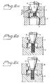
- Fig. 1a shows the first stage in the impression technique, namely the positioning of an impression top 1 on a distance member 2.
- the distance member is fitted in a known manner on a securing element (not shown) by means of a distance screw 3.
- the impression top 1 is secured on the distance member 2 with the aid of a guide pin 4, and the impression top therefore has a continuous guide hole 5 for the guide pin.
- the diameter of the guide hole is slightly larger than the diameter of the guide pin.
- a stop 6 is arranged in the guide hole, with which stop 6 there interacts a flat stop part 7 of the guide pin.
- the guide pin is additionally provided with a lower, narrower, threaded part 8 which is screwed firmly into a corresponding threaded hole in the distance screw 3.
- the flat guide pin when it is tightened, gives only a compressive force which acts on the component which is to be screwed firm.
- the direction of the compressive force is axial, which means that the component will not move in the radial direction.
- the guide pin with the flat stop surface does not therefore have any centring capacity with respect to the play which is always present between the guide pin and the guide hole. This play or clearance can amount to the order of 0.1 to 0.2 mm, and a corresponding error is already built into the impression system at this first stage.
- Figure 1b shows stage 2 in which a distance dummy 9 is fitted on the impression top 1.
- the guide pin 4 is also used here for securing the two components to one another.
- a new error is added to the one already existing in the impression technique.
- Figure 1c shows a further stage in the impression-taking, namely when the gold cylinder 10 is connected to the distance dummy 9. A further centring error is here added to the two earlier ones.
- Figure 2 shows corresponding stages in the impression/model production, but using the new technique according to the invention.
- the impression components i.e. impression top 1, distance dummy 9 and gold cylinder 10
- the guide pin has a conical stop surface 11 which interacts with the edge 6''' of the stop 6.
- the contact force P
- the contact force can be divided up into two force components: one which acts in the axial direction (N) and one which acts in the radial direction (F).
- the radial force component can displace the component in this plane if cone angle and friction coefficient are favourable.
- FIG. 3 A model of how the cone angle ⁇ of the guide pin 4 can be calculated is shown in Fig. 3.
- the contact surface 11 of the guide pin is assumed to interact with a body 12 which can be displaced along a plane 13. Just as the body begins to slide, it is affected by the friction force ⁇ N.
- the friction coefficient ⁇ lies within the range 0.23 ⁇ ⁇ ⁇ 0.55 depending on the material combination in the contact surface.
- Twice the cone angle should therefore be smaller than 120° in order for the component to be able to be displaced. Twice the cone angle should expediently lie within the range 15° ⁇ 2 ⁇ ⁇ 90° since the friction coefficient just before the component begins to slide (start friction) is greater than the sliding friction. The lower limit of 15° is chosen so that the guide pin will not jam.
- the tolerance ranges for distance member, impression top, distance dummy and gold cylinder will be as “small” as possible. This is particularly important for the first three components, since "small" and correctly placed tolerance ranges result in a lower possible play between the components during the impression procedure.
- Figure 4 illustrates, diagrammatically, tolerance ranges for the components, namely distance member (D), impression top (IT), distance dummy (DD) and gold cylinder (G).
- D distance member
- IT impression top
- DD distance dummy
- G gold cylinder
- the tolerance range as regards the gold cylinder (G) will be placed in such a way that there is always a certain play with respect to the distance member. This predetermined and intentional play will allow a dental bridge to be fitted in the mouth cavity even if there is a certain error in relation to the positioning of the distance members in the mouth cavity.
- the intentional play between gold cylinder (G) and distance member (D) is preferably within the range of 0.05 - 0.2 mm.
- the optimized tolerance in combination with the guide pin formed with a conical stop surface, thus minimizes error in the lateral (xy) direction in the production of a model and bridge. Residual error in this direction is then compensated by an intentional and calculated play between gold cylinder and distance member in combination with a non-centring screw connection (gold cylinder/flat gold screw) when the construction is finally anchored in the patient's mouth.
Landscapes
- Health & Medical Sciences (AREA)
- Animal Behavior & Ethology (AREA)
- Orthopedic Medicine & Surgery (AREA)
- Dentistry (AREA)
- Epidemiology (AREA)
- Life Sciences & Earth Sciences (AREA)
- Oral & Maxillofacial Surgery (AREA)
- General Health & Medical Sciences (AREA)
- Public Health (AREA)
- Veterinary Medicine (AREA)
- Dental Prosthetics (AREA)
- Brushes (AREA)
- Dental Tools And Instruments Or Auxiliary Dental Instruments (AREA)
Applications Claiming Priority (2)
| Application Number | Priority Date | Filing Date | Title |
|---|---|---|---|
| SE9302760A SE501661C2 (sv) | 1993-08-26 | 1993-08-26 | Metod vid avtryckstagning och framställning av käkbensförankrade tandproteser |
| SE9302760 | 1993-08-26 |
Publications (2)
| Publication Number | Publication Date |
|---|---|
| EP0640322A1 true EP0640322A1 (de) | 1995-03-01 |
| EP0640322B1 EP0640322B1 (de) | 1999-03-10 |
Family
ID=20390891
Family Applications (1)
| Application Number | Title | Priority Date | Filing Date |
|---|---|---|---|
| EP94850141A Expired - Lifetime EP0640322B1 (de) | 1993-08-26 | 1994-08-23 | Verfahren zum Abdrucknehmen und zur Herstellung von Zahnersatz zur Verankerung im Kieferknochen |
Country Status (6)
| Country | Link |
|---|---|
| US (1) | US5584694A (de) |
| EP (1) | EP0640322B1 (de) |
| AT (1) | ATE177307T1 (de) |
| DE (1) | DE69416912T2 (de) |
| ES (1) | ES2128542T3 (de) |
| SE (1) | SE501661C2 (de) |
Cited By (2)
| Publication number | Priority date | Publication date | Assignee | Title |
|---|---|---|---|---|
| US8038440B2 (en) | 2003-02-28 | 2011-10-18 | Materialise Dental N.V. | Method for placing and manufacturing a dental superstructure, method for placing implants and accessories used thereby |
| US9579170B2 (en) | 2006-05-19 | 2017-02-28 | Materialise Dental N.V. | Method for creating a personalized digital planning file for simulation of dental implant placement |
Families Citing this family (8)
| Publication number | Priority date | Publication date | Assignee | Title |
|---|---|---|---|---|
| US5961329A (en) * | 1997-07-02 | 1999-10-05 | Stucki-Mccormick; Suzanne U. | Combination distraction dental implant and method of use |
| US5961330A (en) * | 1998-04-09 | 1999-10-05 | Sulzer Calcitek Inc. | Vial for dental implant delivery system |
| US6283752B1 (en) | 1998-07-13 | 2001-09-04 | Nobel Biocare Ab | Universal impression coping system |
| FR2836372B1 (fr) * | 2002-02-28 | 2004-06-04 | Obl | Procede et dispositif pour la mise en place d'implants dentaires |
| GB0327822D0 (en) * | 2003-12-01 | 2003-12-31 | Materialise Nv | Method for manufacturing a prosthesis made prior to implant placement |
| GB2509135A (en) | 2012-12-21 | 2014-06-25 | Nobel Biocare Services Ag | An abutment with conical metal adapter |
| GB2509136A (en) | 2012-12-21 | 2014-06-25 | Nobel Biocare Services Ag | Dental component with metal adapter |
| GB2509138A (en) | 2012-12-21 | 2014-06-25 | Nobel Biocare Services Ag | Dental component with screw fixation |
Citations (1)
| Publication number | Priority date | Publication date | Assignee | Title |
|---|---|---|---|---|
| US4708654A (en) * | 1984-11-20 | 1987-11-24 | The Institute For Applied Biotechnology | Positive cast model of an upper and lower jaw, and a method and means for producing such a model |
Family Cites Families (8)
| Publication number | Priority date | Publication date | Assignee | Title |
|---|---|---|---|---|
| SE458499B (sv) * | 1987-06-25 | 1989-04-10 | Astra Meditec Ab | Saett och anordning foer framstaellning av en tandbro |
| US4854872B1 (en) * | 1987-09-24 | 1995-06-27 | Steven G Detsch | Prosthetic implant attachment system and method |
| US4955811A (en) * | 1988-06-23 | 1990-09-11 | Implant Innovations, Inc. | Non-rotational single-tooth prosthodontic restoration |
| SE460944C (sv) * | 1988-11-24 | 1992-07-13 | Titanbron I Aahus Ab | Saett att tillverka en anordning foer uppbaerning av konstgjorda taender |
| DE69003337T2 (de) * | 1989-03-28 | 1994-03-10 | Pierre Berceaux | Positioniereinrichtung für eine zahnprothese. |
| SE463392B (sv) * | 1989-09-15 | 1990-11-19 | Nobelpharma Ab | Distansorgan foer ett kaekbensfoerankrat tandimplantat |
| US5135395A (en) * | 1990-07-05 | 1992-08-04 | Marlin Gerald M | Implant collar and post system |
| US5213502A (en) * | 1992-06-10 | 1993-05-25 | Fereidoun Daftary | Interlockable two-piece impression coping for anatomical dental abutment restorative systems |
-
1993
- 1993-08-26 SE SE9302760A patent/SE501661C2/sv unknown
-
1994
- 1994-08-23 DE DE69416912T patent/DE69416912T2/de not_active Expired - Fee Related
- 1994-08-23 ES ES94850141T patent/ES2128542T3/es not_active Expired - Lifetime
- 1994-08-23 EP EP94850141A patent/EP0640322B1/de not_active Expired - Lifetime
- 1994-08-23 AT AT94850141T patent/ATE177307T1/de not_active IP Right Cessation
- 1994-08-26 US US08/296,804 patent/US5584694A/en not_active Expired - Fee Related
Patent Citations (1)
| Publication number | Priority date | Publication date | Assignee | Title |
|---|---|---|---|---|
| US4708654A (en) * | 1984-11-20 | 1987-11-24 | The Institute For Applied Biotechnology | Positive cast model of an upper and lower jaw, and a method and means for producing such a model |
Cited By (3)
| Publication number | Priority date | Publication date | Assignee | Title |
|---|---|---|---|---|
| US8038440B2 (en) | 2003-02-28 | 2011-10-18 | Materialise Dental N.V. | Method for placing and manufacturing a dental superstructure, method for placing implants and accessories used thereby |
| US8770972B2 (en) | 2003-02-28 | 2014-07-08 | Dentsply Implants Nv | Method for placing and manufacturing a dental superstructure, method for placing implants and accessories used thereby |
| US9579170B2 (en) | 2006-05-19 | 2017-02-28 | Materialise Dental N.V. | Method for creating a personalized digital planning file for simulation of dental implant placement |
Also Published As
| Publication number | Publication date |
|---|---|
| ATE177307T1 (de) | 1999-03-15 |
| EP0640322B1 (de) | 1999-03-10 |
| DE69416912D1 (de) | 1999-04-15 |
| US5584694A (en) | 1996-12-17 |
| SE501661C2 (sv) | 1995-04-10 |
| ES2128542T3 (es) | 1999-05-16 |
| DE69416912T2 (de) | 1999-08-12 |
| SE9302760D0 (sv) | 1993-08-26 |
| SE9302760L (sv) | 1995-02-27 |
Similar Documents
| Publication | Publication Date | Title |
|---|---|---|
| US6974322B2 (en) | Implant-supported dental prosthesis and a process for its production | |
| EP0808609B1 (de) | Satz von Tragkernen für Zahnprothesen | |
| US5342696A (en) | Blank for the production of a dental mould part | |
| EP0506636B1 (de) | Zeitlicher Zylinder | |
| CA2034388C (en) | Impression top | |
| US10792131B2 (en) | Denture reference and registration system | |
| CN107690320B (zh) | 牙齿连接组件和用于制造假牙的方法 | |
| US8303303B2 (en) | Device for determining position | |
| EP0640322B1 (de) | Verfahren zum Abdrucknehmen und zur Herstellung von Zahnersatz zur Verankerung im Kieferknochen | |
| AU591697B2 (en) | Enossal implants | |
| US20060188844A1 (en) | Method and kit for preparing a dental abutment | |
| US20030108845A1 (en) | Framework assembly for providing a passive fit with divergent implants | |
| JPH11502136A (ja) | 歯科用インプラントの円錐状副部材への結合構造 | |
| Carr et al. | The accuracy of implant verification casts compared with casts produced from a rigid transfer coping technique | |
| EP3443932A1 (de) | Stegherstellungs- und zahnprothesenreferenz- und -registrierungssystem | |
| US5055047A (en) | Metal impression confirmation system for dental implants | |
| EP0323421A3 (en) | Spacer for dental implants | |
| JP2609026B2 (ja) | インプラント片座着義歯 | |
| KR20240159037A (ko) | 임플란트 모방 모델 형성방법 및 모방 지그 | |
| EP2351536B1 (de) | Verfahren zur Herstellung einer implantatgestützten Zahnprothese unter Verwendung eines Multifunktionsadapters. | |
| US5775911A (en) | Method and apparatus for producing a shaped article by sonoerosion | |
| JPH0277248A (ja) | 不等構造の咬合器をヒンジ運動軸線と中心位とに関してコーデイネートする方法と装置 | |
| EP3363406A2 (de) | Vorrichtung zum installieren von zahnprothesen auf implantaten | |
| US20240423766A1 (en) | Dental Analog | |
| US12127909B2 (en) | Adjustable locking device and methods of using same |
Legal Events
| Date | Code | Title | Description |
|---|---|---|---|
| PUAI | Public reference made under article 153(3) epc to a published international application that has entered the european phase |
Free format text: ORIGINAL CODE: 0009012 |
|
| AK | Designated contracting states |
Kind code of ref document: A1 Designated state(s): AT BE CH DE ES FR GB LI NL |
|
| 17P | Request for examination filed |
Effective date: 19950207 |
|
| RAP1 | Party data changed (applicant data changed or rights of an application transferred) |
Owner name: NOBEL BIOCARE AB (REG. NO. 556002-0231) |
|
| GRAG | Despatch of communication of intention to grant |
Free format text: ORIGINAL CODE: EPIDOS AGRA |
|
| 17Q | First examination report despatched |
Effective date: 19970925 |
|
| GRAG | Despatch of communication of intention to grant |
Free format text: ORIGINAL CODE: EPIDOS AGRA |
|
| GRAH | Despatch of communication of intention to grant a patent |
Free format text: ORIGINAL CODE: EPIDOS IGRA |
|
| GRAH | Despatch of communication of intention to grant a patent |
Free format text: ORIGINAL CODE: EPIDOS IGRA |
|
| GRAA | (expected) grant |
Free format text: ORIGINAL CODE: 0009210 |
|
| AK | Designated contracting states |
Kind code of ref document: B1 Designated state(s): AT BE CH DE ES FR GB LI NL |
|
| REF | Corresponds to: |
Ref document number: 177307 Country of ref document: AT Date of ref document: 19990315 Kind code of ref document: T |
|
| REG | Reference to a national code |
Ref country code: CH Ref legal event code: NV Representative=s name: E. BLUM & CO. PATENTANWAELTE Ref country code: CH Ref legal event code: EP |
|
| ET | Fr: translation filed | ||
| REF | Corresponds to: |
Ref document number: 69416912 Country of ref document: DE Date of ref document: 19990415 |
|
| REG | Reference to a national code |
Ref country code: ES Ref legal event code: FG2A Ref document number: 2128542 Country of ref document: ES Kind code of ref document: T3 |
|
| PLBE | No opposition filed within time limit |
Free format text: ORIGINAL CODE: 0009261 |
|
| STAA | Information on the status of an ep patent application or granted ep patent |
Free format text: STATUS: NO OPPOSITION FILED WITHIN TIME LIMIT |
|
| 26N | No opposition filed | ||
| PGFP | Annual fee paid to national office [announced via postgrant information from national office to epo] |
Ref country code: GB Payment date: 20010822 Year of fee payment: 8 |
|
| PGFP | Annual fee paid to national office [announced via postgrant information from national office to epo] |
Ref country code: AT Payment date: 20010824 Year of fee payment: 8 |
|
| PGFP | Annual fee paid to national office [announced via postgrant information from national office to epo] |
Ref country code: BE Payment date: 20010829 Year of fee payment: 8 |
|
| PGFP | Annual fee paid to national office [announced via postgrant information from national office to epo] |
Ref country code: NL Payment date: 20010831 Year of fee payment: 8 |
|
| REG | Reference to a national code |
Ref country code: GB Ref legal event code: IF02 |
|
| PGFP | Annual fee paid to national office [announced via postgrant information from national office to epo] |
Ref country code: ES Payment date: 20020610 Year of fee payment: 9 |
|
| PGFP | Annual fee paid to national office [announced via postgrant information from national office to epo] |
Ref country code: CH Payment date: 20020711 Year of fee payment: 9 |
|
| PG25 | Lapsed in a contracting state [announced via postgrant information from national office to epo] |
Ref country code: GB Free format text: LAPSE BECAUSE OF NON-PAYMENT OF DUE FEES Effective date: 20020823 Ref country code: AT Free format text: LAPSE BECAUSE OF NON-PAYMENT OF DUE FEES Effective date: 20020823 |
|
| PGFP | Annual fee paid to national office [announced via postgrant information from national office to epo] |
Ref country code: FR Payment date: 20020827 Year of fee payment: 9 |
|
| PG25 | Lapsed in a contracting state [announced via postgrant information from national office to epo] |
Ref country code: BE Free format text: LAPSE BECAUSE OF NON-PAYMENT OF DUE FEES Effective date: 20020831 |
|
| PGFP | Annual fee paid to national office [announced via postgrant information from national office to epo] |
Ref country code: DE Payment date: 20021024 Year of fee payment: 9 |
|
| BERE | Be: lapsed |
Owner name: *NOBEL BIOCARE A.B. (REG. NO. 556002-0231) Effective date: 20020831 |
|
| PG25 | Lapsed in a contracting state [announced via postgrant information from national office to epo] |
Ref country code: NL Free format text: LAPSE BECAUSE OF NON-PAYMENT OF DUE FEES Effective date: 20030301 |
|
| GBPC | Gb: european patent ceased through non-payment of renewal fee |
Effective date: 20020823 |
|
| NLV4 | Nl: lapsed or anulled due to non-payment of the annual fee |
Effective date: 20030301 |
|
| PG25 | Lapsed in a contracting state [announced via postgrant information from national office to epo] |
Ref country code: ES Free format text: LAPSE BECAUSE OF NON-PAYMENT OF DUE FEES Effective date: 20030825 |
|
| PG25 | Lapsed in a contracting state [announced via postgrant information from national office to epo] |
Ref country code: LI Free format text: LAPSE BECAUSE OF NON-PAYMENT OF DUE FEES Effective date: 20030831 Ref country code: CH Free format text: LAPSE BECAUSE OF NON-PAYMENT OF DUE FEES Effective date: 20030831 |
|
| PG25 | Lapsed in a contracting state [announced via postgrant information from national office to epo] |
Ref country code: DE Free format text: LAPSE BECAUSE OF NON-PAYMENT OF DUE FEES Effective date: 20040302 |
|
| REG | Reference to a national code |
Ref country code: CH Ref legal event code: PL |
|
| PG25 | Lapsed in a contracting state [announced via postgrant information from national office to epo] |
Ref country code: FR Free format text: LAPSE BECAUSE OF NON-PAYMENT OF DUE FEES Effective date: 20040430 |
|
| REG | Reference to a national code |
Ref country code: FR Ref legal event code: ST |
|
| REG | Reference to a national code |
Ref country code: ES Ref legal event code: FD2A Effective date: 20030825 |