EP0640404A1 - Couvercle - Google Patents
Couvercle Download PDFInfo
- Publication number
- EP0640404A1 EP0640404A1 EP93113510A EP93113510A EP0640404A1 EP 0640404 A1 EP0640404 A1 EP 0640404A1 EP 93113510 A EP93113510 A EP 93113510A EP 93113510 A EP93113510 A EP 93113510A EP 0640404 A1 EP0640404 A1 EP 0640404A1
- Authority
- EP
- European Patent Office
- Prior art keywords
- cover cap
- threaded bolt
- projections
- thread
- face
- Prior art date
- Legal status (The legal status is an assumption and is not a legal conclusion. Google has not performed a legal analysis and makes no representation as to the accuracy of the status listed.)
- Granted
Links
- 239000002184 metal Substances 0.000 claims abstract description 44
- 229910052751 metal Inorganic materials 0.000 claims abstract description 44
- 238000000034 method Methods 0.000 claims abstract description 36
- 230000008569 process Effects 0.000 claims abstract description 11
- 238000003466 welding Methods 0.000 claims description 33
- 239000003973 paint Substances 0.000 claims description 11
- 238000003825 pressing Methods 0.000 claims description 11
- 230000005540 biological transmission Effects 0.000 claims 1
- 238000010422 painting Methods 0.000 description 7
- 239000000463 material Substances 0.000 description 6
- 230000008901 benefit Effects 0.000 description 4
- 238000004519 manufacturing process Methods 0.000 description 4
- 230000007797 corrosion Effects 0.000 description 3
- 238000005260 corrosion Methods 0.000 description 3
- 239000004922 lacquer Substances 0.000 description 3
- 239000000155 melt Substances 0.000 description 3
- 239000000243 solution Substances 0.000 description 3
- 230000007704 transition Effects 0.000 description 3
- 239000002699 waste material Substances 0.000 description 3
- PXHVJJICTQNCMI-UHFFFAOYSA-N Nickel Chemical compound [Ni] PXHVJJICTQNCMI-UHFFFAOYSA-N 0.000 description 2
- 230000009471 action Effects 0.000 description 2
- 239000011248 coating agent Substances 0.000 description 2
- 238000000576 coating method Methods 0.000 description 2
- 230000000284 resting effect Effects 0.000 description 2
- RYGMFSIKBFXOCR-UHFFFAOYSA-N Copper Chemical compound [Cu] RYGMFSIKBFXOCR-UHFFFAOYSA-N 0.000 description 1
- 241001295925 Gegenes Species 0.000 description 1
- 229910000831 Steel Inorganic materials 0.000 description 1
- 230000006978 adaptation Effects 0.000 description 1
- 238000007796 conventional method Methods 0.000 description 1
- 229910052802 copper Inorganic materials 0.000 description 1
- 239000010949 copper Substances 0.000 description 1
- 238000005520 cutting process Methods 0.000 description 1
- 230000000694 effects Effects 0.000 description 1
- 230000002349 favourable effect Effects 0.000 description 1
- 239000002920 hazardous waste Substances 0.000 description 1
- 230000009191 jumping Effects 0.000 description 1
- 229910001338 liquidmetal Inorganic materials 0.000 description 1
- 229910052759 nickel Inorganic materials 0.000 description 1
- 239000012811 non-conductive material Substances 0.000 description 1
- 230000003287 optical effect Effects 0.000 description 1
- 230000035515 penetration Effects 0.000 description 1
- 229920000642 polymer Polymers 0.000 description 1
- 239000011241 protective layer Substances 0.000 description 1
- 230000009467 reduction Effects 0.000 description 1
- 238000000926 separation method Methods 0.000 description 1
- 238000007592 spray painting technique Methods 0.000 description 1
- 238000005507 spraying Methods 0.000 description 1
- 239000010959 steel Substances 0.000 description 1
- 238000003860 storage Methods 0.000 description 1
- 230000008719 thickening Effects 0.000 description 1
- 230000000007 visual effect Effects 0.000 description 1
- 238000005493 welding type Methods 0.000 description 1
- 238000009736 wetting Methods 0.000 description 1
Images


Classifications
-
- H—ELECTRICITY
- H01—ELECTRIC ELEMENTS
- H01R—ELECTRICALLY-CONDUCTIVE CONNECTIONS; STRUCTURAL ASSOCIATIONS OF A PLURALITY OF MUTUALLY-INSULATED ELECTRICAL CONNECTING ELEMENTS; COUPLING DEVICES; CURRENT COLLECTORS
- H01R4/00—Electrically-conductive connections between two or more conductive members in direct contact, i.e. touching one another; Means for effecting or maintaining such contact; Electrically-conductive connections having two or more spaced connecting locations for conductors and using contact members penetrating insulation
- H01R4/58—Electrically-conductive connections between two or more conductive members in direct contact, i.e. touching one another; Means for effecting or maintaining such contact; Electrically-conductive connections having two or more spaced connecting locations for conductors and using contact members penetrating insulation characterised by the form or material of the contacting members
- H01R4/64—Connections between or with conductive parts having primarily a non-electric function, e.g. frame, casing, rail
-
- B—PERFORMING OPERATIONS; TRANSPORTING
- B05—SPRAYING OR ATOMISING IN GENERAL; APPLYING FLUENT MATERIALS TO SURFACES, IN GENERAL
- B05B—SPRAYING APPARATUS; ATOMISING APPARATUS; NOZZLES
- B05B12/00—Arrangements for controlling delivery; Arrangements for controlling the spray area
- B05B12/16—Arrangements for controlling delivery; Arrangements for controlling the spray area for controlling the spray area
- B05B12/20—Masking elements, i.e. elements defining uncoated areas on an object to be coated
Definitions
- the invention relates to a method for producing a paint-free connection to an add-on part by means of a protruding threaded bolt of a metal sheet, and to a device for carrying out this method.
- a typical application for this is in automotive engineering, where threaded bolts are attached to a sheet metal part by means of stud welding or rivets or spot welding a so-called T-screw (threaded bolts with sheet metal tabs protruding on both sides at the end) etc. and attachments are attached to the sheet metal in a metallic connection after the sheet has been painted.
- T-screw threaded bolts with sheet metal tabs protruding on both sides at the end
- both a nut screwed onto the threaded bolt and a slid-on sleeve with a retracting counter-directed barb or projections can be used to fasten the attachment, such as the earth cable, to the sheet metal surface with sufficient pressure.
- the latter can only be released without destroying or losing the contact pressure if special measures are provided, such as arranging the projections only in two opposite areas, so that by pressing the cover cap in a direction transverse to the connecting axis of the two areas, the projections in or can be disengaged from the thread.
- cover cap which is preferably made of metal, is used both for covering and for later pressing on.
- the still loose threaded bolt is first screwed into the cover cap, and then the entire unit is brought up to the sheet metal by means of a corresponding handling device and riveted or bolt-welded.
- the use of a metallic cover cap has heretofore been seen as a disadvantage, since the arc could inadmissibly build up between the sheet metal and the facing end face of the cover cap instead of between the sheet metal and the facing end face of the threaded bolt.
- the assembly time is greatly reduced, since the handling tool does not first take hold of the cover cap, after fastening the bolt and unscrewing the cover cap there must be a separation of the tool and cover cap, with the mounting nut subsequently being accommodated in the same or analog tool.
- the cover cap is inserted into the handling tool, for example a motor-driven hexagon nut, only once at the beginning of the process, and the screwing forwards or backwards is then carried out therewith.
- the end face and thus the flange of the cover cap facing the sheet metal is chosen so large in its outer dimensions that it is the same size or larger than the contact surface of the add-on part which later lies directly against the sheet metal.
- the sleeve at the end of the earth cable to be fastened could have an annular area which protrudes against the sheet metal and has a defined inner and outer diameter, which is matched to the area around the bolt which is kept free of paint, while the overall dimensions of the eyelet may even be larger at the end of the ground cable.
- the cover cap In order not to allow an arc between the sheet and the end face of the cover cap facing it when welding the threaded bolt, the cover cap is not screwed on so far in this process step that its cover surface is already at the same height as the end face of the threaded bolt facing the plate.
- metal cover caps according to the invention there is a further advantage that the handling during stud welding is exclusively by contact with the The outer surface of the cover cap is sufficient, since the current flow from the metal cover cap via the welding bolt into the sheet metal is thus ensured, which was not possible with the disposable cover caps made of non-conductive material previously used, so that there is a grasping of the protruding from the cover cap Parts of the threaded bolt due to the electrically conductive arrangement was necessary.
- the free-running end of the threaded stud is moved against the sheet metal and welded, while in the other case the welding stud has a widened, plate-shaped, round base at its end to be connected to the sheet.
- This base is used so that despite the poses caused by the welding, there is as flat a contact surface as possible for the attachment of the add-on part, namely the ring-shaped end face of the base of the threaded bolt pointing away from the sheet metal, around the thread, while the arising Threats on the lower level, namely the contact surface of the opposite end face of the base and the outer surface of the sheet.
- an undercut is incorporated into the annular edge of the inner circumference of the striking surface of the covering cap directed against the sheet metal, which absorbs the resulting poses if the welding stud does not have a widened base described above. If the welding stud has a base, the lower, thread-less and therefore thicker end of the welding stud is accommodated in the undercut.
- the paint also applied to the cover cap is then damaged as little as possible and thus corresponds to the visual requirements when tightening or loosening the usually.
- polygon e.g. Hexagon
- formed outer circumference does not occur in the edge areas of the pressing surfaces, as is usual in the case of normal hexagon nuts, that is to say in the vicinity of the contact edges of the six pressing surfaces, but is offset toward the center of the pressing surfaces. This prevents the paint from jumping off at the edge areas of the individual pressing surfaces in the vicinity of their contact edges.
- the cover cap - if it is made of steel - is protected against corrosion anyway by appropriate coating with nickel, copper or the like, the lacquer applied to the cover cap additionally improves the corrosion resistance.
- protrusions are used that are arranged in segments, in order to enable the cover cap to be pushed on quickly instead of being screwed on, it must be made of metal or another material there - be elastically deformable in the transverse direction to the projections so that the projections which are in engagement with the thread become disengaged and, when the deformation force is removed, return to their original position in order to another pushing open, this time to fasten the cable harness, to offer the same old strength again.
- the undercut on the inner circumference of the face of the cover cap does not have a rectangular cross-section from a bevel of this annular edge, but instead, e.g. has a rectangular cross section, the surfaces of which lie essentially parallel to the end face and the inner circumference of the opening of the cover cap. This prevents the liquid metal spraying away during stud welding from being thrown back by the bevel in the direction of the thread.
- Fig. 1 basically shows the procedure, with a distinction being made as to whether the welding stud used has a widened base or not and whether the attachment can be placed over the free end of the welding stud or pushed sideways onto the welding stud.
- the procedure is shown if the cover cap 6 is screwed onto the threaded bolt 3 in whole or in part from the beginning and is handled together with it during welding.
- the procedure is shown in which the welding stud is handled alone until it is firmly connected to the sheet metal, and only then is the cover cap 6 applied.
- the two parts can be non-location-specific beforehand and possibly. fully automatically connected to each other to the desired extent, for example screwed, so that only a single item has to be stored at the production site itself.
- the functional unit 28, consisting of threaded bolt 3 and cover cap 6, is guided against the sheet metal 1, with which it is welded at a sufficiently small distance or by means of an arc using the stud welding method.
- the majority of threaded bolts 3 with a widened base 5 are used, on which the end cap 7 of the cover cap 6 is seated.
- the base 5 can easily be held on the circumference by means of holding tongs 27 during the welding process, so that the welding process takes place reliably between the base surface of the base 5 and the sheet metal 1.
- gripping or picking up is also possible directly and exclusively on the hexagon socket 11 of the cover cap 6 by means of a tool such as a nut 26 during the approach and welding.
- a tool such as a nut 26 during the approach and welding.
- the threaded bolt 3 must protrude sufficiently far from the cover cap 6 during welding to only between the free thread surface of the threaded bolt 3 and the Sheet 1 to cause an arc.
- the cover cap 6 is screwed in the direction against the sheet metal until the cover cap bears with its end face 7 on the counter surface 4.
- this is the sheet metal surface surrounding the threaded bolt, in the case of a threaded bolt with a base 5 this is the line surface directed upward in FIG. 1.
- the now lacquered cover cap 6 is first completely unscrewed from the threaded bolt 3 by means of a nut 26, then component 2 is placed over the threaded bolt 3 and the cover cap 6 is screwed on again until the add-on part 2 is pressed against the paint-free counterpart, either the base of the threaded bolt or the sheet metal, with the required nominal pressure.
- the lower row of pictures shows the use of non-closed, for example U-shaped attachments that can be pushed laterally onto the threaded bolt. It is not necessary to completely unscrew the cap, it is sufficient to screw up by a distance that must at least correspond to the thickness of the attachment.
- the cover cap After pushing the add-on part and resting it on the paint-free counter surface, the cover cap is screwed back in the direction of the sheet metal to fasten the add-on part. This saves valuable assembly time since only a shorter distance has to be screwed back and forth again.
- Fig. 2 shows a cross-sectional view with a threaded bolt 3 without a widened base.
- the threaded bolt 3 which is welded to the sheet 1, can be seen.
- a melt 24 is formed briefly in the transition area between the two parts, and thereby also a projection 21 that arises in the annular edge between the threaded bolt 3 and the sheet metal 1.
- the thread 13 of the threaded bolt 3 does not extend to the sheet-metal end 1, but ends one or a few mm beforehand.
- the thread 13 of the threaded bolt 3 fits on an opposing external thread 16 or correspondingly shaped projections 17 in the inner circumference of the cover cap 6.
- This consists of a nut part 9 in the middle, which is designed on the outside in a known manner as an external hexagon 11, and in Internal thread has the internal thread 16.
- a widened flange 25 adjoins the nut part 9, the outer diameter of which determines the size of the end face 7 and thus the covered area on the counter surface.
- the outer diameter of the covering end face 7 of the cover cap 6 is chosen to match the outer diameter of the support surface 20 of the attachment 2 so that the outer diameter of the end face 7 is the same or slightly larger is the outer diameter of the contact surface 20 of the attachment 2.
- the cap part 10 connects with an approximately semicircular outer contour at the free end.
- the cap part and nut part are preferably formed in one piece, but a multi-part design and simple connection by means of locking elements etc. is also possible.
- the nut part 9 applying the contact pressure could be made of metal, while the only purpose of covering 10 would be plastic, etc.
- the diameter of the blind hole 18 can be larger in the area of the cap part 10 than in the area of the nut part 9 or the internal thread 16.
- this undercut 8 has no function.
- the base 5 usually has a round outer circumference and in adaptation thereto, the flange 25 also has a round outer circumference at the lower end of the cover cap 6.
- the melt 24 now occurs in the connection area between the lower end face of the base 5 in FIG. 3 and the sheet 1.
- a two-part embodiment of the cover cap is also shown, in which a nose 28 as the outer circumference at the lower end of the cap part 10 is engaged behind a projection 29 on the inner circumference of the nut part.
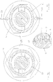
- FIGS. 4a to 4c show a cover cap 6, which on its inner circumference does not have a circumferential internal thread 6, but rather only at two opposite points of projections 17.
- FIGS. 4a and 4b show a cross-sectional representation along the line IV-IV of FIG. 3.
- Fig. 4a it can be seen how in the unloaded state of the cap 6, the projections 17 engage in the threads of the external thread 13 of the threaded bolt 3, and thus give the same positive locking effect as with a circumferential thread. The fine adjustment can still be made by screwing the cover cap 6 against the threaded bolt 3.
- the projections 17 are designed accordingly, screwing on from the free end of the threaded bolt 3 can be avoided by, for example, pushing the cover cap with the projections 17 onto the bolt in the axial direction when the individual projections are sufficiently elastic, to snap over the slopes of the individual threads in the next.
- an embodiment as shown in FIG. 4c is favorable, in which the individual projections 17 do not protrude to the bottom of the threads of the thread 13, but end beforehand and have a sufficient free length, interrupted by notches between the individual projections 17, have to allow a deflection and thus a pushing.
- the solution with projections 17 is particularly interesting in the two-part design of the cover cap, since in this case the elasticity of a cap part made of plastic can be used, while nut part 9 and flange 25 consist of metal or less elastic, more dimensionally dimensioned plastic.
Landscapes
- Connection Of Plates (AREA)
- Pens And Brushes (AREA)
- Finger-Pressure Massage (AREA)
- Coating With Molten Metal (AREA)
- Sealing Devices (AREA)
- Motor Or Generator Frames (AREA)
- Tents Or Canopies (AREA)
Priority Applications (4)
| Application Number | Priority Date | Filing Date | Title |
|---|---|---|---|
| AT93113510T ATE159870T1 (de) | 1993-08-24 | 1993-08-24 | Abdeckkappe |
| EP93113510A EP0640404B1 (fr) | 1993-08-24 | 1993-08-24 | Couvercle |
| ES93113510T ES2112362T3 (es) | 1993-08-24 | 1993-08-24 | Caperuza de proteccion. |
| DE59307648T DE59307648D1 (de) | 1993-08-24 | 1993-08-24 | Abdeckkappe |
Applications Claiming Priority (1)
| Application Number | Priority Date | Filing Date | Title |
|---|---|---|---|
| EP93113510A EP0640404B1 (fr) | 1993-08-24 | 1993-08-24 | Couvercle |
Publications (2)
| Publication Number | Publication Date |
|---|---|
| EP0640404A1 true EP0640404A1 (fr) | 1995-03-01 |
| EP0640404B1 EP0640404B1 (fr) | 1997-11-05 |
Family
ID=8213201
Family Applications (1)
| Application Number | Title | Priority Date | Filing Date |
|---|---|---|---|
| EP93113510A Expired - Lifetime EP0640404B1 (fr) | 1993-08-24 | 1993-08-24 | Couvercle |
Country Status (4)
| Country | Link |
|---|---|
| EP (1) | EP0640404B1 (fr) |
| AT (1) | ATE159870T1 (fr) |
| DE (1) | DE59307648D1 (fr) |
| ES (1) | ES2112362T3 (fr) |
Cited By (19)
| Publication number | Priority date | Publication date | Assignee | Title |
|---|---|---|---|---|
| EP0641944A1 (fr) * | 1993-09-08 | 1995-03-08 | Emhart Inc. | Boulon à masse avec écrou |
| GB2311662A (en) * | 1996-03-29 | 1997-10-01 | Sicame Electrical Dev Ltd | Clamp for connecting conductors |
| DE19749383A1 (de) * | 1997-11-07 | 1999-05-27 | Trw Nelson Bolzenschweisstechn | Kragenbolzen mit Verdrehsicherung |
| EP1017129A3 (fr) * | 1998-12-31 | 2000-11-15 | Emhart Inc. | Goujon de fixation électrique |
| DE19937047A1 (de) * | 1999-08-05 | 2001-02-08 | Opel Adam Ag | Für ein Kraftfahrzeug bestimmter Massekontakt |
| WO2002056422A1 (fr) * | 2001-01-10 | 2002-07-18 | Newfrey Llc | Boulon electrique de contact revetu et procede de fixation d'un contact electrique |
| EP1037318A3 (fr) * | 1999-03-10 | 2003-06-25 | Newfrey LLC | Goujon soudé |
| EP1705751A1 (fr) * | 2005-03-26 | 2006-09-27 | Jungheinrich Aktiengesellschaft | Connexion électrique pour une unité de commande de puissance d'un chariot élévateur à batteries |
| US7156670B2 (en) | 2001-01-10 | 2007-01-02 | Newfrey Llc | Electrical capped contact stud and method of fastening an electrical contact |
| DE102007046690A1 (de) | 2007-09-28 | 2009-04-02 | Volkswagen Ag | Anschweißbares Befestigungselement mit einem Kontaktbolzen für wenigstens einen elektrischen Kontakt |
| US7788802B2 (en) | 2001-01-10 | 2010-09-07 | Newfrey Llc | Method of fastening an electrical contact |
| US8287219B2 (en) | 2006-11-20 | 2012-10-16 | Newfrey Llc | Fastening arrangement |
| DE102004050675B4 (de) * | 2004-10-18 | 2015-05-07 | Volkswagen Ag | Befestigungsanordnung für wenigstens einen Kabelschuh an einem Schweißbolzen |
| DE102015216259A1 (de) * | 2015-08-26 | 2017-03-02 | Bayerische Motoren Werke Aktiengesellschaft | Masseanschluss für ein Aluminiumbau-, insbesondere Karosserieteil |
| EP3217481A1 (fr) | 2016-03-10 | 2017-09-13 | Newfrey LLC | Système de mise à la terre électrique et procédé de production de connexion à la terre |
| DE102016114512A1 (de) * | 2016-08-05 | 2018-02-08 | Dr. Ing. H.C. F. Porsche Aktiengesellschaft | Verfahren zur Herstellung eines Batteriegehäuses |
| DE102006012761B4 (de) | 2006-03-17 | 2019-03-21 | Volkswagen Ag | Befestigungsanordnung für wenigstens einen Kabelschuh an einem Schweißbolzen |
| WO2019105556A1 (fr) * | 2017-11-30 | 2019-06-06 | Abb Schweiz Ag | Agencement de joint, kit de pièces et procédé |
| DE102019214348A1 (de) * | 2019-09-20 | 2021-03-25 | Zf Friedrichshafen Ag | Anordnung zum Abdecken von Schraubenauflageflächen an einem Flansch eines Getriebegehäuses und Montage derselben |
Families Citing this family (1)
| Publication number | Priority date | Publication date | Assignee | Title |
|---|---|---|---|---|
| CN107214029B (zh) * | 2017-08-07 | 2022-07-12 | 中国重汽集团济南动力有限公司 | 一种自吸式螺柱防护装置 |
Citations (5)
| Publication number | Priority date | Publication date | Assignee | Title |
|---|---|---|---|---|
| DE543319C (de) * | 1932-02-04 | Hermann Struebe | Schutzkappe oder Schutzhuelse zum Aufstecken auf vorstehende Koerperteile beim Farbauftrag auf Flaechen | |
| US3922050A (en) * | 1974-03-21 | 1975-11-25 | Boeing Co | Blind, shank expanding electrical terminal structure |
| EP0307932A1 (fr) * | 1987-09-18 | 1989-03-22 | Nagoya Oilchemical Co., Ltd. | Cache |
| JPH0549114A (ja) * | 1991-08-14 | 1993-02-26 | Toshiba Corp | 電気機器構造部材の導電結合部材とその接地処理方法 |
| EP0540030A2 (fr) * | 1991-10-31 | 1993-05-05 | PROFIL-Verbindungstechnik GmbH & Co. KG | Vis de mise à la terre |
-
1993
- 1993-08-24 ES ES93113510T patent/ES2112362T3/es not_active Expired - Lifetime
- 1993-08-24 AT AT93113510T patent/ATE159870T1/de not_active IP Right Cessation
- 1993-08-24 DE DE59307648T patent/DE59307648D1/de not_active Expired - Lifetime
- 1993-08-24 EP EP93113510A patent/EP0640404B1/fr not_active Expired - Lifetime
Patent Citations (5)
| Publication number | Priority date | Publication date | Assignee | Title |
|---|---|---|---|---|
| DE543319C (de) * | 1932-02-04 | Hermann Struebe | Schutzkappe oder Schutzhuelse zum Aufstecken auf vorstehende Koerperteile beim Farbauftrag auf Flaechen | |
| US3922050A (en) * | 1974-03-21 | 1975-11-25 | Boeing Co | Blind, shank expanding electrical terminal structure |
| EP0307932A1 (fr) * | 1987-09-18 | 1989-03-22 | Nagoya Oilchemical Co., Ltd. | Cache |
| JPH0549114A (ja) * | 1991-08-14 | 1993-02-26 | Toshiba Corp | 電気機器構造部材の導電結合部材とその接地処理方法 |
| EP0540030A2 (fr) * | 1991-10-31 | 1993-05-05 | PROFIL-Verbindungstechnik GmbH & Co. KG | Vis de mise à la terre |
Non-Patent Citations (1)
| Title |
|---|
| PATENT ABSTRACTS OF JAPAN vol. 17, no. 351 (E - 1392) 2 July 1993 (1993-07-02) * |
Cited By (27)
| Publication number | Priority date | Publication date | Assignee | Title |
|---|---|---|---|---|
| EP0641944A1 (fr) * | 1993-09-08 | 1995-03-08 | Emhart Inc. | Boulon à masse avec écrou |
| GB2311662A (en) * | 1996-03-29 | 1997-10-01 | Sicame Electrical Dev Ltd | Clamp for connecting conductors |
| GB2311662B (en) * | 1996-03-29 | 2000-09-13 | Sicame Electrical Dev Ltd | Connector |
| DE19749383A1 (de) * | 1997-11-07 | 1999-05-27 | Trw Nelson Bolzenschweisstechn | Kragenbolzen mit Verdrehsicherung |
| EP1017129A3 (fr) * | 1998-12-31 | 2000-11-15 | Emhart Inc. | Goujon de fixation électrique |
| EP1037318A3 (fr) * | 1999-03-10 | 2003-06-25 | Newfrey LLC | Goujon soudé |
| DE19937047A1 (de) * | 1999-08-05 | 2001-02-08 | Opel Adam Ag | Für ein Kraftfahrzeug bestimmter Massekontakt |
| US7788802B2 (en) | 2001-01-10 | 2010-09-07 | Newfrey Llc | Method of fastening an electrical contact |
| US7156670B2 (en) | 2001-01-10 | 2007-01-02 | Newfrey Llc | Electrical capped contact stud and method of fastening an electrical contact |
| WO2002056422A1 (fr) * | 2001-01-10 | 2002-07-18 | Newfrey Llc | Boulon electrique de contact revetu et procede de fixation d'un contact electrique |
| US6877997B2 (en) | 2001-01-10 | 2005-04-12 | Newfrey Llc | Electrical capped contact stud and method of fastening an electrical contact |
| DE102004050675B4 (de) * | 2004-10-18 | 2015-05-07 | Volkswagen Ag | Befestigungsanordnung für wenigstens einen Kabelschuh an einem Schweißbolzen |
| EP1705751A1 (fr) * | 2005-03-26 | 2006-09-27 | Jungheinrich Aktiengesellschaft | Connexion électrique pour une unité de commande de puissance d'un chariot élévateur à batteries |
| DE102006012761B4 (de) | 2006-03-17 | 2019-03-21 | Volkswagen Ag | Befestigungsanordnung für wenigstens einen Kabelschuh an einem Schweißbolzen |
| DE102006056065B4 (de) | 2006-11-20 | 2018-08-09 | Newfrey Llc | Vormontierte Kontaktiereinheit und Befestigungsanordnung |
| US8523505B2 (en) | 2006-11-20 | 2013-09-03 | Newfrey Llc | Fastening arrangement |
| US8287219B2 (en) | 2006-11-20 | 2012-10-16 | Newfrey Llc | Fastening arrangement |
| DE102007046690A1 (de) | 2007-09-28 | 2009-04-02 | Volkswagen Ag | Anschweißbares Befestigungselement mit einem Kontaktbolzen für wenigstens einen elektrischen Kontakt |
| DE102015216259A1 (de) * | 2015-08-26 | 2017-03-02 | Bayerische Motoren Werke Aktiengesellschaft | Masseanschluss für ein Aluminiumbau-, insbesondere Karosserieteil |
| EP3217481A1 (fr) | 2016-03-10 | 2017-09-13 | Newfrey LLC | Système de mise à la terre électrique et procédé de production de connexion à la terre |
| DE102016104396A1 (de) | 2016-03-10 | 2017-09-14 | Newfrey Llc | Elektrisches Massesystem und Masseverbindungs-Herstellungsverfahren |
| DE102016114512A1 (de) * | 2016-08-05 | 2018-02-08 | Dr. Ing. H.C. F. Porsche Aktiengesellschaft | Verfahren zur Herstellung eines Batteriegehäuses |
| WO2019105556A1 (fr) * | 2017-11-30 | 2019-06-06 | Abb Schweiz Ag | Agencement de joint, kit de pièces et procédé |
| CN111148889A (zh) * | 2017-11-30 | 2020-05-12 | Abb瑞士股份有限公司 | 密封装置、零件套件及方法 |
| CN111148889B (zh) * | 2017-11-30 | 2022-03-18 | Abb瑞士股份有限公司 | 密封装置、零件套件及方法 |
| US11542979B2 (en) | 2017-11-30 | 2023-01-03 | Abb Schweiz Ag | Seal arrangement, kit of parts and method |
| DE102019214348A1 (de) * | 2019-09-20 | 2021-03-25 | Zf Friedrichshafen Ag | Anordnung zum Abdecken von Schraubenauflageflächen an einem Flansch eines Getriebegehäuses und Montage derselben |
Also Published As
| Publication number | Publication date |
|---|---|
| ES2112362T3 (es) | 1998-04-01 |
| ATE159870T1 (de) | 1997-11-15 |
| DE59307648D1 (de) | 1997-12-11 |
| EP0640404B1 (fr) | 1997-11-05 |
Similar Documents
| Publication | Publication Date | Title |
|---|---|---|
| EP0640404B1 (fr) | Couvercle | |
| DE102006056065B4 (de) | Vormontierte Kontaktiereinheit und Befestigungsanordnung | |
| DE69512867T2 (de) | Befestigungselement zum Zusammenbau von Platten sowie Herstellungsverfahren | |
| DE69227084T2 (de) | Erdungsbolzen | |
| EP3309414B1 (fr) | Élément de fonction pour fixation étanche aux fluides sur une pièce de tôlerie, ensemble de montage et procédé | |
| DE19609684A1 (de) | Schutzring gegen Kontaktkorrosion | |
| DE102010015179A1 (de) | Anordnung zur Befestigung von Fahrzeugbauteilen an einer Rohbaukarosserie eines Fahrzeugs | |
| DE9312678U1 (de) | Abdecksystem | |
| EP1360744A1 (fr) | Fixation pour contact electrique | |
| DE9308096U1 (de) | Anordnung zur Verliersicherung von Schrauben | |
| DE102013007036A1 (de) | Kontaktiereinrichtung für eine elektrische Kontaktanordnung sowie Verfahren zu deren Herstellung | |
| DE102005052309B4 (de) | Anschlußbolzen, Anschlußelement und elektrisch leitende Kupplungsvorrichtung | |
| DE102007026239A1 (de) | Kontaktanordnung und Verfahren zum Herstellen einer elektrischen Verbindung | |
| EP4095398A1 (fr) | Dispositif de compensation des tolérances entre deux composants à connecter | |
| EP3993169A1 (fr) | Élément de connexion électrique destiné à l'application par liaison par complémentarité de forme ou par technique de soudage à une pièce en tôle | |
| EP3293404A1 (fr) | Pastille plastique et systeme comprenant une telle pastille plastique | |
| DE102007027104A1 (de) | Fixierelement zur elektrischen Kontaktierung eines lackierten Massebolzens in einer Fahrzeugkarosserie | |
| DE102009024335B4 (de) | Befestigungsschraube und ihre Verwendung und ein Verfahren zur Überwachung der Qualität der Schraubverbindung sowie eine Verbindungseinheit | |
| DE19735731A1 (de) | Kraftfahrzeugleuchte für den Einbau von außen | |
| DE102019133891A1 (de) | Funktionselement | |
| WO2007057323A1 (fr) | Coupleur électriquement conducteur | |
| DE102008051821A1 (de) | Nietteil in einer Formvertiefung | |
| EP1450055B1 (fr) | Ecrou borgne en métal | |
| DE10138800A1 (de) | Elektrischer Kontaktbolzen mit Hutmutter sowie Verfahren zum Befestigen eines elektrischen Kontaktes | |
| EP2088645B1 (fr) | Système de fixation |
Legal Events
| Date | Code | Title | Description |
|---|---|---|---|
| PUAI | Public reference made under article 153(3) epc to a published international application that has entered the european phase |
Free format text: ORIGINAL CODE: 0009012 |
|
| AK | Designated contracting states |
Kind code of ref document: A1 Designated state(s): AT BE DE ES FR GB IT NL PT SE |
|
| RBV | Designated contracting states (corrected) |
Designated state(s): AT BE DE ES FR GB IT NL PT SE |
|
| 17P | Request for examination filed |
Effective date: 19950630 |
|
| RAP1 | Party data changed (applicant data changed or rights of an application transferred) |
Owner name: NEDSCHROEF PLETTENBERG GMBH |
|
| GRAG | Despatch of communication of intention to grant |
Free format text: ORIGINAL CODE: EPIDOS AGRA |
|
| 17Q | First examination report despatched |
Effective date: 19970120 |
|
| GRAH | Despatch of communication of intention to grant a patent |
Free format text: ORIGINAL CODE: EPIDOS IGRA |
|
| GRAH | Despatch of communication of intention to grant a patent |
Free format text: ORIGINAL CODE: EPIDOS IGRA |
|
| GRAA | (expected) grant |
Free format text: ORIGINAL CODE: 0009210 |
|
| AK | Designated contracting states |
Kind code of ref document: B1 Designated state(s): AT BE DE ES FR GB IT NL PT SE |
|
| REF | Corresponds to: |
Ref document number: 159870 Country of ref document: AT Date of ref document: 19971115 Kind code of ref document: T |
|
| GBT | Gb: translation of ep patent filed (gb section 77(6)(a)/1977) |
Effective date: 19971106 |
|
| REF | Corresponds to: |
Ref document number: 59307648 Country of ref document: DE Date of ref document: 19971211 |
|
| ET | Fr: translation filed | ||
| ITF | It: translation for a ep patent filed | ||
| REG | Reference to a national code |
Ref country code: ES Ref legal event code: FG2A Ref document number: 2112362 Country of ref document: ES Kind code of ref document: T3 |
|
| REG | Reference to a national code |
Ref country code: PT Ref legal event code: SC4A Free format text: AVAILABILITY OF NATIONAL TRANSLATION Effective date: 19980130 |
|
| PLBE | No opposition filed within time limit |
Free format text: ORIGINAL CODE: 0009261 |
|
| STAA | Information on the status of an ep patent application or granted ep patent |
Free format text: STATUS: NO OPPOSITION FILED WITHIN TIME LIMIT |
|
| 26N | No opposition filed | ||
| REG | Reference to a national code |
Ref country code: GB Ref legal event code: IF02 |
|
| PGFP | Annual fee paid to national office [announced via postgrant information from national office to epo] |
Ref country code: AT Payment date: 20070822 Year of fee payment: 15 |
|
| PGFP | Annual fee paid to national office [announced via postgrant information from national office to epo] |
Ref country code: GB Payment date: 20070828 Year of fee payment: 15 |
|
| PGFP | Annual fee paid to national office [announced via postgrant information from national office to epo] |
Ref country code: NL Payment date: 20070820 Year of fee payment: 15 Ref country code: BE Payment date: 20070823 Year of fee payment: 15 |
|
| REG | Reference to a national code |
Ref country code: PT Ref legal event code: MM4A Free format text: LAPSE DUE TO NON-PAYMENT OF FEES Effective date: 20090224 |
|
| GBPC | Gb: european patent ceased through non-payment of renewal fee |
Effective date: 20080824 |
|
| PG25 | Lapsed in a contracting state [announced via postgrant information from national office to epo] |
Ref country code: AT Free format text: LAPSE BECAUSE OF NON-PAYMENT OF DUE FEES Effective date: 20080824 |
|
| NLV4 | Nl: lapsed or anulled due to non-payment of the annual fee |
Effective date: 20090301 |
|
| PG25 | Lapsed in a contracting state [announced via postgrant information from national office to epo] |
Ref country code: PT Free format text: LAPSE BECAUSE OF NON-PAYMENT OF DUE FEES Effective date: 20090224 Ref country code: NL Free format text: LAPSE BECAUSE OF NON-PAYMENT OF DUE FEES Effective date: 20090301 |
|
| PG25 | Lapsed in a contracting state [announced via postgrant information from national office to epo] |
Ref country code: BE Free format text: LAPSE BECAUSE OF NON-PAYMENT OF DUE FEES Effective date: 20080831 |
|
| PG25 | Lapsed in a contracting state [announced via postgrant information from national office to epo] |
Ref country code: GB Free format text: LAPSE BECAUSE OF NON-PAYMENT OF DUE FEES Effective date: 20080824 |
|
| PGFP | Annual fee paid to national office [announced via postgrant information from national office to epo] |
Ref country code: PT Payment date: 20070813 Year of fee payment: 15 |
|
| PGFP | Annual fee paid to national office [announced via postgrant information from national office to epo] |
Ref country code: SE Payment date: 20120823 Year of fee payment: 20 |
|
| PGFP | Annual fee paid to national office [announced via postgrant information from national office to epo] |
Ref country code: DE Payment date: 20120725 Year of fee payment: 20 Ref country code: IT Payment date: 20120824 Year of fee payment: 20 Ref country code: ES Payment date: 20120824 Year of fee payment: 20 Ref country code: FR Payment date: 20120831 Year of fee payment: 20 |
|
| REG | Reference to a national code |
Ref country code: DE Ref legal event code: R071 Ref document number: 59307648 Country of ref document: DE |
|
| REG | Reference to a national code |
Ref country code: SE Ref legal event code: EUG |
|
| PG25 | Lapsed in a contracting state [announced via postgrant information from national office to epo] |
Ref country code: DE Free format text: LAPSE BECAUSE OF EXPIRATION OF PROTECTION Effective date: 20130827 |
|
| REG | Reference to a national code |
Ref country code: ES Ref legal event code: FD2A Effective date: 20140925 |
|
| PG25 | Lapsed in a contracting state [announced via postgrant information from national office to epo] |
Ref country code: ES Free format text: LAPSE BECAUSE OF EXPIRATION OF PROTECTION Effective date: 20130825 |