EP0640724A2 - Machine de chantier, en particulier véhicule excavateur - Google Patents
Machine de chantier, en particulier véhicule excavateur Download PDFInfo
- Publication number
- EP0640724A2 EP0640724A2 EP94112370A EP94112370A EP0640724A2 EP 0640724 A2 EP0640724 A2 EP 0640724A2 EP 94112370 A EP94112370 A EP 94112370A EP 94112370 A EP94112370 A EP 94112370A EP 0640724 A2 EP0640724 A2 EP 0640724A2
- Authority
- EP
- European Patent Office
- Prior art keywords
- piston
- arm piece
- cylinder unit
- construction machine
- arm
- Prior art date
- Legal status (The legal status is an assumption and is not a legal conclusion. Google has not performed a legal analysis and makes no representation as to the accuracy of the status listed.)
- Granted
Links
- 238000010276 construction Methods 0.000 title claims description 14
- 230000005540 biological transmission Effects 0.000 description 2
- 238000009412 basement excavation Methods 0.000 description 1
- 238000005452 bending Methods 0.000 description 1
- 230000000994 depressogenic effect Effects 0.000 description 1
- 238000011161 development Methods 0.000 description 1
- 230000018109 developmental process Effects 0.000 description 1
Images

Classifications
-
- E—FIXED CONSTRUCTIONS
- E02—HYDRAULIC ENGINEERING; FOUNDATIONS; SOIL SHIFTING
- E02F—DREDGING; SOIL-SHIFTING
- E02F3/00—Dredgers; Soil-shifting machines
- E02F3/04—Dredgers; Soil-shifting machines mechanically-driven
- E02F3/28—Dredgers; Soil-shifting machines mechanically-driven with digging tools mounted on a dipper- or bucket-arm, i.e. there is either one arm or a pair of arms, e.g. dippers, buckets
- E02F3/30—Dredgers; Soil-shifting machines mechanically-driven with digging tools mounted on a dipper- or bucket-arm, i.e. there is either one arm or a pair of arms, e.g. dippers, buckets with a dipper-arm pivoted on a cantilever beam, i.e. boom
- E02F3/301—Dredgers; Soil-shifting machines mechanically-driven with digging tools mounted on a dipper- or bucket-arm, i.e. there is either one arm or a pair of arms, e.g. dippers, buckets with a dipper-arm pivoted on a cantilever beam, i.e. boom with more than two arms (boom included), e.g. two-part boom with additional dipper-arm
-
- E—FIXED CONSTRUCTIONS
- E02—HYDRAULIC ENGINEERING; FOUNDATIONS; SOIL SHIFTING
- E02F—DREDGING; SOIL-SHIFTING
- E02F3/00—Dredgers; Soil-shifting machines
- E02F3/04—Dredgers; Soil-shifting machines mechanically-driven
- E02F3/28—Dredgers; Soil-shifting machines mechanically-driven with digging tools mounted on a dipper- or bucket-arm, i.e. there is either one arm or a pair of arms, e.g. dippers, buckets
- E02F3/30—Dredgers; Soil-shifting machines mechanically-driven with digging tools mounted on a dipper- or bucket-arm, i.e. there is either one arm or a pair of arms, e.g. dippers, buckets with a dipper-arm pivoted on a cantilever beam, i.e. boom
- E02F3/32—Dredgers; Soil-shifting machines mechanically-driven with digging tools mounted on a dipper- or bucket-arm, i.e. there is either one arm or a pair of arms, e.g. dippers, buckets with a dipper-arm pivoted on a cantilever beam, i.e. boom working downwardly and towards the machine, e.g. with backhoes
Definitions
- the invention relates to a construction machine, in particular an excavator vehicle, with a frame and a boom which has an inner arm piece articulated on the frame side and an outer arm piece carrying the work tool and optionally at least one further middle arm piece, each arm piece being articulated by means of an articulated arm associated therewith Piston-cylinder unit relative to the frame or the arm piece adjacent to the frame is pivotable about an axis of articulation.
- Such a construction machine with a boom of individually hydraulically pivotable arm pieces is known, both as a wheeled vehicle with a digging spoon as a working tool (DE 41 24 461 C) and as a tracked vehicle with a loading shovel as a working tool (DE 24 11 051 C).
- each arm piece has both at its inner end and at its outer end a hinge axis, which connects it to the arm piece or mounting bracket that is adjacent on the frame side and to the arm piece or tool that is adjacent to the tool.
- each arm piece points for attaching the piston-cylinder units on two articulation axes, one in which the piston-cylinder unit engages to pivot itself, and one from which the piston-cylinder unit starts to pivot the arm piece or tool adjacent to the tool.
- the piston-cylinder units can each be arranged in the vertical central plane of the boom or laterally offset next to the arm piece in question, possibly in a double design symmetrical to the vertical central plane of the boom.
- the piston-cylinder units Since the pivoting of adjacent arm pieces by means of the piston-cylinder unit acting between them to ensure a force transmission arm requires a triangular arrangement of the articulation axis between the two arm pieces and the two articulation axes of the piston-cylinder unit, the piston-cylinder units have so far been arranged so that they are at least largely extend outside of the arm pieces, i.e. in the case of the arrangement in the vertical boom center plane below or above the arm pieces, insofar as these assume a more or less horizontal position or in front of or behind the arm pieces insofar as these assume a more or less vertical position. This leads to largely exposed piston-cylinder units even if they do not run laterally next to the arm pieces but in their vertical center plane.
- the piston-cylinder units are poorly protected, so that there is a risk of undesirable transverse forces acting on the piston-cylinder units when hitting obstacles in view of the rough construction site operation in connection with carelessness during operation. Accordingly, damage to the piston-cylinder units can hardly be avoided, even if these piston-cylinder units are designed to be particularly stable, but this also represents an undesirable additional effort.
- the invention has for its object to improve the construction machine in this regard and the piston-cylinder units or at least one of them without significant additional effort, in particular to protect the most vulnerable, so that damage or bending of the piston-cylinder unit are largely excluded.
- At least one piston-cylinder unit is arranged entirely or predominantly within the associated arm piece.
- an excavator vehicle 1 which is equipped with four wheels 2 and has a chassis frame 3, on which a driver's cab 5 is mounted by means of a slewing ring 4.
- a housing 6 At the rear of the driver's cab 5 is a housing 6 provided that receives the traction drive and the hydraulic devices and control devices for the excavator vehicle 1.
- a connector 7 At the front of the driver's cab there is a connector 7 on which a mounting bracket 8 is attached.
- a shield 11 is attached above the links 9 and 10, which can be raised and lowered by means of a piston-cylinder unit 12. In the position of the shield 11 according to FIG. 1 depressed on the road surface 13, the excavator vehicle 1 is given a firm stand in order to be able to carry out the intended excavation work.
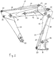
- a boom 14 is connected to the mounting bracket 8 and is composed of an inner arm piece 15, a middle arm piece 16 and an outer arm piece 17.
- the work tool 18, in the illustrated embodiment a digging spoon, is connected to the latter.
- the mounting bracket 8, the arm pieces 15 to 17 and the working tool 18 are connected to one another by horizontal articulated axes 19, 20, 21 and 22.
- An inner piston-cylinder unit 23, a middle piston-cylinder unit 24 and an outer piston-cylinder unit 25 are provided for the individual pivoting of the individual arm pieces.
- Another piston-cylinder unit 26 serves to pivot the digging spoon 18.
- Each piston-cylinder unit 23 to 26 has a cylinder 27 articulated at the closed end on the vehicle side and a piston rod 28 which can be extended therefrom and which is articulated more at the tool end at its free end.
- the cylinder 27 of the inner piston-cylinder unit 23 is articulated on a bearing projection 29 projecting from the mounting bracket 8, while the piston rod 28 of the piston-cylinder unit 26 is articulated centrally on a toggle link 30, the ends of which are on the one hand on the outer arm piece 17 and on the other hand on the digging spoon 18 are articulated.
- Each arm piece thus has two articulation axes 31 and 32 or 33 and 34 or 35 and 36, on which the piston rod 28 of the associated piston-cylinder unit 23 to 25 engages or the Cylinder 27 of the subsequent piston-cylinder unit 24 to 26 is connected.
- the middle piston-cylinder unit 24 runs within the middle arm piece 16, which is designed with a closed box profile, only the cylinder end articulated on the inner arm piece 15 in the articulation axis 32 protruding from the middle arm piece 16.
- the articulation axis 33 of the middle piston-cylinder unit 24 is closer to the articulation axis 21 between the middle arm piece 16 and the outer arm piece 17 than at the articulation axis 20 between the inner arm piece 15 and the middle arm piece 16.
- the middle arm piece 16 which receives the middle piston-cylinder unit 24, has at its frame-side end a pair of lateral bearing plates 37, which extend approximately transversely to the longitudinal axis of the middle arm piece 16 and beyond and beyond it the ends of the hinge axis 20 and the pivot axis 34.
- the middle arm piece 16 assumes an essentially vertical position during the digging work and thereby penetrates the road surface 13 (the earth's surface). Therefore, there is an increased risk of the boom 14 colliding with obstacles in the region of the middle arm piece 16.
- the piston-cylinder unit 24, and in particular its extended piston rod 28 extends within this area, it is largely protected against damage from corresponding external influences, since it is received and enclosed by the middle arm piece 16.
Landscapes
- Engineering & Computer Science (AREA)
- Mechanical Engineering (AREA)
- Mining & Mineral Resources (AREA)
- Civil Engineering (AREA)
- General Engineering & Computer Science (AREA)
- Structural Engineering (AREA)
- Component Parts Of Construction Machinery (AREA)
- Shovels (AREA)
- Vehicle Cleaning, Maintenance, Repair, Refitting, And Outriggers (AREA)
Applications Claiming Priority (2)
| Application Number | Priority Date | Filing Date | Title |
|---|---|---|---|
| DE4328449A DE4328449A1 (de) | 1993-08-24 | 1993-08-24 | Baumaschine, insbesondere Baggerfahrzeug |
| DE4328449 | 1993-08-24 |
Publications (3)
| Publication Number | Publication Date |
|---|---|
| EP0640724A2 true EP0640724A2 (fr) | 1995-03-01 |
| EP0640724A3 EP0640724A3 (fr) | 1995-07-19 |
| EP0640724B1 EP0640724B1 (fr) | 1999-10-27 |
Family
ID=6495908
Family Applications (1)
| Application Number | Title | Priority Date | Filing Date |
|---|---|---|---|
| EP94112370A Expired - Lifetime EP0640724B1 (fr) | 1993-08-24 | 1994-08-08 | Machine de chantier, en particulier véhicule excavateur |
Country Status (4)
| Country | Link |
|---|---|
| EP (1) | EP0640724B1 (fr) |
| AT (1) | ATE186089T1 (fr) |
| DE (2) | DE4328449A1 (fr) |
| NO (1) | NO943011L (fr) |
Cited By (1)
| Publication number | Priority date | Publication date | Assignee | Title |
|---|---|---|---|---|
| EP2208827A3 (fr) * | 2009-01-16 | 2014-04-23 | Kobelco Construction Machinery Co. Ltd. | Flèche d'un engin de travail |
Family Cites Families (6)
| Publication number | Priority date | Publication date | Assignee | Title |
|---|---|---|---|---|
| US3057494A (en) * | 1959-01-30 | 1962-10-09 | Wain Roy Corp | Excavating apparatus |
| US3666124A (en) * | 1970-10-15 | 1972-05-30 | Wain Roy | Lifting and excavating apparatus |
| GB2082144A (en) * | 1980-04-09 | 1982-03-03 | Caterpillar Tractor Co | Load carrying structure and method of manufacture therefor |
| DE8512238U1 (de) * | 1985-04-25 | 1985-08-14 | O & K Orenstein & Koppel Ag, 1000 Berlin | Mobilbagger |
| DE3575755D1 (de) * | 1985-12-23 | 1990-03-08 | Komatsu Mfg Co Ltd | Vorrichtung zum antreiben des arbeitswerkzeuges eines baggers. |
| DE9003519U1 (de) * | 1990-03-27 | 1990-07-12 | Atlas Weyhausen GmbH, 2870 Delmenhorst | Ausleger für einen Löffelbagger od.dgl. |
-
1993
- 1993-08-24 DE DE4328449A patent/DE4328449A1/de not_active Withdrawn
-
1994
- 1994-08-08 AT AT94112370T patent/ATE186089T1/de not_active IP Right Cessation
- 1994-08-08 DE DE59408858T patent/DE59408858D1/de not_active Expired - Fee Related
- 1994-08-08 EP EP94112370A patent/EP0640724B1/fr not_active Expired - Lifetime
- 1994-08-15 NO NO943011A patent/NO943011L/no unknown
Cited By (1)
| Publication number | Priority date | Publication date | Assignee | Title |
|---|---|---|---|---|
| EP2208827A3 (fr) * | 2009-01-16 | 2014-04-23 | Kobelco Construction Machinery Co. Ltd. | Flèche d'un engin de travail |
Also Published As
| Publication number | Publication date |
|---|---|
| NO943011D0 (no) | 1994-08-15 |
| EP0640724B1 (fr) | 1999-10-27 |
| DE4328449A1 (de) | 1995-03-02 |
| ATE186089T1 (de) | 1999-11-15 |
| EP0640724A3 (fr) | 1995-07-19 |
| DE59408858D1 (de) | 1999-12-02 |
| NO943011L (no) | 1995-02-27 |
Similar Documents
| Publication | Publication Date | Title |
|---|---|---|
| DE3048291A1 (de) | "bagger" | |
| DE1915825A1 (de) | Bodenbearbeitungsgeraet | |
| EP0625614A2 (fr) | Engin de chantier polyvalent | |
| EP1621682B1 (fr) | Appareil de transbordement. | |
| EP1008284A2 (fr) | Accouplement télescopique d'outil pour véhicule motorisé | |
| EP0073360A2 (fr) | Faucheuse | |
| EP3459900A1 (fr) | Support en arc pourvu de pièce rabattable | |
| EP0065118A2 (fr) | Excavatrice | |
| DE4233730C2 (de) | Maschine für Erdarbeiten | |
| EP1245740A1 (fr) | Véhicule de chantier avec un outil de travail | |
| DE2808591A1 (de) | Pneumatisches streugeraet | |
| DE60007227T2 (de) | Selbstangetriebener Wagen mit teleskopischem Arm und Hebungsarm | |
| EP3416912B1 (fr) | Unité de bras pour l'accès en hauteur pour une machine mobile pour l'accès en hauteur, machine pour l'accès en hauteur, et utilisation de cette unité de bras pour l'accès en hauteur. | |
| EP0640724B1 (fr) | Machine de chantier, en particulier véhicule excavateur | |
| DE1142320B (de) | Loeffelbagger | |
| DE102010009177A1 (de) | Mast, insbesondere Arbeitsmast für Autobetonpumpen, sowie Autobetonpumpe mit einem solchen Mast | |
| DE3148960A1 (de) | Hydraulikbagger oder hydraulischer kran mit hydraulisch verstellbarem fahrerhaus | |
| DE8804501U1 (de) | Baggerlöffel | |
| DE19746702A1 (de) | Schwenkadapter | |
| DE4225948A1 (de) | Ladegerät | |
| DE2612879C2 (de) | Fahrbarer Löffelbagger | |
| DE9016037U1 (de) | Fahrbares Arbeitsgerät | |
| AT390815B (de) | An einem zugfahrzeug loesbar befestigbarer grabenbagger | |
| EP0594160A1 (fr) | Machine à utiliser dans des pépinières, jardins et analogues | |
| EP4108835A1 (fr) | Minipelle à flèche variable |
Legal Events
| Date | Code | Title | Description |
|---|---|---|---|
| PUAI | Public reference made under article 153(3) epc to a published international application that has entered the european phase |
Free format text: ORIGINAL CODE: 0009012 |
|
| AK | Designated contracting states |
Kind code of ref document: A2 Designated state(s): AT CH DE FR IT LI SE |
|
| PUAL | Search report despatched |
Free format text: ORIGINAL CODE: 0009013 |
|
| AK | Designated contracting states |
Kind code of ref document: A3 Designated state(s): AT CH DE FR IT LI SE |
|
| 17P | Request for examination filed |
Effective date: 19960113 |
|
| 17Q | First examination report despatched |
Effective date: 19980702 |
|
| GRAG | Despatch of communication of intention to grant |
Free format text: ORIGINAL CODE: EPIDOS AGRA |
|
| GRAG | Despatch of communication of intention to grant |
Free format text: ORIGINAL CODE: EPIDOS AGRA |
|
| GRAH | Despatch of communication of intention to grant a patent |
Free format text: ORIGINAL CODE: EPIDOS IGRA |
|
| GRAH | Despatch of communication of intention to grant a patent |
Free format text: ORIGINAL CODE: EPIDOS IGRA |
|
| GRAA | (expected) grant |
Free format text: ORIGINAL CODE: 0009210 |
|
| AK | Designated contracting states |
Kind code of ref document: B1 Designated state(s): AT CH DE FR IT LI SE |
|
| REF | Corresponds to: |
Ref document number: 186089 Country of ref document: AT Date of ref document: 19991115 Kind code of ref document: T |
|
| REG | Reference to a national code |
Ref country code: CH Ref legal event code: EP |
|
| REF | Corresponds to: |
Ref document number: 59408858 Country of ref document: DE Date of ref document: 19991202 |
|
| ET | Fr: translation filed | ||
| ITF | It: translation for a ep patent filed | ||
| PG25 | Lapsed in a contracting state [announced via postgrant information from national office to epo] |
Ref country code: AT Free format text: LAPSE BECAUSE OF NON-PAYMENT OF DUE FEES Effective date: 20000808 |
|
| PLBE | No opposition filed within time limit |
Free format text: ORIGINAL CODE: 0009261 |
|
| STAA | Information on the status of an ep patent application or granted ep patent |
Free format text: STATUS: NO OPPOSITION FILED WITHIN TIME LIMIT |
|
| PG25 | Lapsed in a contracting state [announced via postgrant information from national office to epo] |
Ref country code: LI Free format text: LAPSE BECAUSE OF NON-PAYMENT OF DUE FEES Effective date: 20000831 Ref country code: CH Free format text: LAPSE BECAUSE OF NON-PAYMENT OF DUE FEES Effective date: 20000831 |
|
| 26N | No opposition filed | ||
| REG | Reference to a national code |
Ref country code: CH Ref legal event code: PL |
|
| PGFP | Annual fee paid to national office [announced via postgrant information from national office to epo] |
Ref country code: FR Payment date: 20010725 Year of fee payment: 8 |
|
| PGFP | Annual fee paid to national office [announced via postgrant information from national office to epo] |
Ref country code: SE Payment date: 20010806 Year of fee payment: 8 |
|
| PGFP | Annual fee paid to national office [announced via postgrant information from national office to epo] |
Ref country code: DE Payment date: 20010814 Year of fee payment: 8 |
|
| PG25 | Lapsed in a contracting state [announced via postgrant information from national office to epo] |
Ref country code: SE Free format text: LAPSE BECAUSE OF NON-PAYMENT OF DUE FEES Effective date: 20020809 |
|
| PG25 | Lapsed in a contracting state [announced via postgrant information from national office to epo] |
Ref country code: DE Free format text: LAPSE BECAUSE OF NON-PAYMENT OF DUE FEES Effective date: 20030301 |
|
| EUG | Se: european patent has lapsed | ||
| PG25 | Lapsed in a contracting state [announced via postgrant information from national office to epo] |
Ref country code: FR Free format text: LAPSE BECAUSE OF NON-PAYMENT OF DUE FEES Effective date: 20030430 |
|
| REG | Reference to a national code |
Ref country code: FR Ref legal event code: ST |
|
| PG25 | Lapsed in a contracting state [announced via postgrant information from national office to epo] |
Ref country code: IT Free format text: LAPSE BECAUSE OF NON-PAYMENT OF DUE FEES;WARNING: LAPSES OF ITALIAN PATENTS WITH EFFECTIVE DATE BEFORE 2007 MAY HAVE OCCURRED AT ANY TIME BEFORE 2007. THE CORRECT EFFECTIVE DATE MAY BE DIFFERENT FROM THE ONE RECORDED. Effective date: 20050808 |