EP0641067A2 - Dispositif et méthode de contrôle pour le démarrage d'un moteur - Google Patents
Dispositif et méthode de contrôle pour le démarrage d'un moteur Download PDFInfo
- Publication number
- EP0641067A2 EP0641067A2 EP94113069A EP94113069A EP0641067A2 EP 0641067 A2 EP0641067 A2 EP 0641067A2 EP 94113069 A EP94113069 A EP 94113069A EP 94113069 A EP94113069 A EP 94113069A EP 0641067 A2 EP0641067 A2 EP 0641067A2
- Authority
- EP
- European Patent Office
- Prior art keywords
- motor
- time
- speed
- rotational speed
- target speed
- Prior art date
- Legal status (The legal status is an assumption and is not a legal conclusion. Google has not performed a legal analysis and makes no representation as to the accuracy of the status listed.)
- Withdrawn
Links
Images



Classifications
-
- H—ELECTRICITY
- H04—ELECTRIC COMMUNICATION TECHNIQUE
- H04N—PICTORIAL COMMUNICATION, e.g. TELEVISION
- H04N1/00—Scanning, transmission or reproduction of documents or the like, e.g. facsimile transmission; Details thereof
- H04N1/04—Scanning arrangements, i.e. arrangements for the displacement of active reading or reproducing elements relative to the original or reproducing medium, or vice versa
- H04N1/047—Detection, control or error compensation of scanning velocity or position
- H04N1/0476—Indicating the scanning velocity
-
- G—PHYSICS
- G02—OPTICS
- G02B—OPTICAL ELEMENTS, SYSTEMS OR APPARATUS
- G02B26/00—Optical devices or arrangements for the control of light using movable or deformable optical elements
- G02B26/08—Optical devices or arrangements for the control of light using movable or deformable optical elements for controlling the direction of light
- G02B26/10—Scanning systems
- G02B26/12—Scanning systems using multifaceted mirrors
- G02B26/121—Mechanical drive devices for polygonal mirrors
- G02B26/122—Control of the scanning speed of the polygonal mirror
-
- H—ELECTRICITY
- H02—GENERATION; CONVERSION OR DISTRIBUTION OF ELECTRIC POWER
- H02P—CONTROL OR REGULATION OF ELECTRIC MOTORS, ELECTRIC GENERATORS OR DYNAMO-ELECTRIC CONVERTERS; CONTROLLING TRANSFORMERS, REACTORS OR CHOKE COILS
- H02P1/00—Arrangements for starting electric motors or dynamo-electric converters
- H02P1/02—Details of starting control
- H02P1/04—Means for controlling progress of starting sequence in dependence upon time or upon current, speed, or other motor parameter
-
- H—ELECTRICITY
- H04—ELECTRIC COMMUNICATION TECHNIQUE
- H04N—PICTORIAL COMMUNICATION, e.g. TELEVISION
- H04N1/00—Scanning, transmission or reproduction of documents or the like, e.g. facsimile transmission; Details thereof
- H04N1/04—Scanning arrangements, i.e. arrangements for the displacement of active reading or reproducing elements relative to the original or reproducing medium, or vice versa
- H04N1/047—Detection, control or error compensation of scanning velocity or position
- H04N1/053—Detection, control or error compensation of scanning velocity or position in main scanning direction, e.g. synchronisation of line start or picture elements in a line
-
- H—ELECTRICITY
- H04—ELECTRIC COMMUNICATION TECHNIQUE
- H04N—PICTORIAL COMMUNICATION, e.g. TELEVISION
- H04N1/00—Scanning, transmission or reproduction of documents or the like, e.g. facsimile transmission; Details thereof
- H04N1/04—Scanning arrangements, i.e. arrangements for the displacement of active reading or reproducing elements relative to the original or reproducing medium, or vice versa
- H04N1/113—Scanning arrangements, i.e. arrangements for the displacement of active reading or reproducing elements relative to the original or reproducing medium, or vice versa using oscillating or rotating mirrors
- H04N1/1135—Scanning arrangements, i.e. arrangements for the displacement of active reading or reproducing elements relative to the original or reproducing medium, or vice versa using oscillating or rotating mirrors for the main-scan only
-
- H—ELECTRICITY
- H04—ELECTRIC COMMUNICATION TECHNIQUE
- H04N—PICTORIAL COMMUNICATION, e.g. TELEVISION
- H04N2201/00—Indexing scheme relating to scanning, transmission or reproduction of documents or the like, and to details thereof
- H04N2201/04—Scanning arrangements
- H04N2201/047—Detection, control or error compensation of scanning velocity or position
- H04N2201/04701—Detection of scanning velocity or position
- H04N2201/0471—Detection of scanning velocity or position using dedicated detectors
-
- H—ELECTRICITY
- H04—ELECTRIC COMMUNICATION TECHNIQUE
- H04N—PICTORIAL COMMUNICATION, e.g. TELEVISION
- H04N2201/00—Indexing scheme relating to scanning, transmission or reproduction of documents or the like, and to details thereof
- H04N2201/04—Scanning arrangements
- H04N2201/047—Detection, control or error compensation of scanning velocity or position
- H04N2201/04701—Detection of scanning velocity or position
- H04N2201/04715—Detection of scanning velocity or position by detecting marks or the like, e.g. slits
- H04N2201/04724—Detection of scanning velocity or position by detecting marks or the like, e.g. slits on a separate encoder wheel
-
- H—ELECTRICITY
- H04—ELECTRIC COMMUNICATION TECHNIQUE
- H04N—PICTORIAL COMMUNICATION, e.g. TELEVISION
- H04N2201/00—Indexing scheme relating to scanning, transmission or reproduction of documents or the like, and to details thereof
- H04N2201/04—Scanning arrangements
- H04N2201/047—Detection, control or error compensation of scanning velocity or position
- H04N2201/04701—Detection of scanning velocity or position
- H04N2201/04734—Detecting at frequent intervals, e.g. once per line for sub-scan control
-
- H—ELECTRICITY
- H04—ELECTRIC COMMUNICATION TECHNIQUE
- H04N—PICTORIAL COMMUNICATION, e.g. TELEVISION
- H04N2201/00—Indexing scheme relating to scanning, transmission or reproduction of documents or the like, and to details thereof
- H04N2201/04—Scanning arrangements
- H04N2201/047—Detection, control or error compensation of scanning velocity or position
- H04N2201/04753—Control or error compensation of scanning position or velocity
- H04N2201/04755—Control or error compensation of scanning position or velocity by controlling the position or movement of a scanning element or carriage, e.g. of a polygonal mirror, of a drive motor
-
- Y—GENERAL TAGGING OF NEW TECHNOLOGICAL DEVELOPMENTS; GENERAL TAGGING OF CROSS-SECTIONAL TECHNOLOGIES SPANNING OVER SEVERAL SECTIONS OF THE IPC; TECHNICAL SUBJECTS COVERED BY FORMER USPC CROSS-REFERENCE ART COLLECTIONS [XRACs] AND DIGESTS
- Y10—TECHNICAL SUBJECTS COVERED BY FORMER USPC
- Y10S—TECHNICAL SUBJECTS COVERED BY FORMER USPC CROSS-REFERENCE ART COLLECTIONS [XRACs] AND DIGESTS
- Y10S388/00—Electricity: motor control systems
- Y10S388/907—Specific control circuit element or device
- Y10S388/921—Timer or time delay means
Definitions
- the present invention relates to a motor start examining device and method for examining, when the rotational speed of a motor is predetermined, a state from the time when the rotation of the motor is started to the time when the rotational speed of the motor reaches the predetermined rotational speed. More specifically, the present invention relates to a start examining device and method of a motor for driving a Polygonal mirror which is provided for an image forming apparatus or the like.
- the rotation of the motor In order to accurately write the image by the laser beam, the rotation of the motor must be rigidly controlled. That is, constant-speed rotation control of the motor for rotating the Polygonal mirror is carried out.
- the waiting time is set to a relatively longer time (for example, approximately 10 to 20 seconds) in consideration of the variation in the starting characteristics of each motor.
- a problem in such a technique is that the time required until the rotation of the motor is stabilized differs from one image forming apparatus to another, thereby to make it difficult to uniformly determine the waiting time.
- the time required until the rotation of the motor is stabilized after starting the motor greatly differs from one image forming apparatus to another.
- the time required until the rotation of the motor is stabilized may, in some cases, be longer as the motor is used. If such variations in the time required until the rotation of the motor is stabilized for each image forming apparatus is taken into consideration, the waiting time may be set to the longest time. In this case, however, the waiting time required until the laser light source lights up to start image formation since the motor for driving the Polygonal mirror was started becomes significantly long.
- the waiting time is set to a relatively short time
- the chattering of the motor may not, in some cases, completely subside even after an elapse of the waiting time.
- the image forming operation is started after the elapse of the waiting time. If the rotation stability signal is broken after the image forming operation is started, however, it is judged that a failure has occurred, whereby the image forming operation is interrupted. Particularly even when the rotation stability signal is slightly broken so that the distortion of an image formed, for example, is not a problem, the image forming operation is interrupted.
- the motor has been started earlier in consideration of the rise time of the motor.
- the driving time of the motor may, in some cases, be longer than necessary.
- the facsimile of a laser recording type is taken as an example. In this example, it is considered that the motor is started immediately after the receiving of an image is started. In the facsimile, however, it may, in some cases, take only several seconds and in the other cases, take 20 minutes to receive an image corresponding to one page. If the motor is started immediately after the receiving is started, therefore, the motor is uselessly rotated and driven. As a result, the life of the motor may be reduced.
- An object of the present invention is to provide a start examining device and method for examining, when a motor whose rotational speed is determined is started, whether or not the rotational speed of the motor correctly reaches the determined rotational speed within a predetermined time period after the rotation of the motor is started.
- Another object of the present invention is to provide a start examining device and method for judging whether or not a motor is stabilized at a predetermined rotational speed within a short time period after the motor is started even if there are variations in the characteristics of a motor for driving a Polygonal mirror and the characteristics of a control circuit in an image forming apparatus of a laser recording type.
- the device examines the rotating state of a motor immediately after starting the motor. Therefore, the device comprises a timer, a speed detecting unit for detecting the rotational speed of the motor, a stability signal outputting circuit, and a judging circuit.
- the timer starts to measure time in response to the start of the supply of power to the motor, to output a time-up signal when it measures a predetermined rise time.
- the stability signal outputting circuit outputs a stability signal when the speed detected by the speed detecting unit is maintained in a predetermined relationship with a predetermined target speed. For example, the stability signal is outputted when the detected speed is in a speed range between a speed slightly higher than the target speed and a speed slightly lower than the target speed.
- the judging circuit judges that the motor is stabilized at the target speed when the stability signal is outputted continuously for an examining time shorter than the rise time before the time-up signal is outputted from the timer.
- the judging circuit does not judge that the motor is stabilized at the target speed even if the stability signal is only continuously outputted during the examining time and then, waits until a predetermined waiting time has elapsed, and judges that the motor is stabilized at the target speed if the stability signal is outputted even after an elapse of the waiting time.
- the judging circuit waits, when the stability signal is not outputted after an elapse of the waiting time, until a second waiting time has further elapsed, and judges that the motor is stabilized at the target speed if the stability signal is outputted after an elapse of the second waiting time.
- Fig. 1 is a block diagram showing the electrical construction of a laser beam printer incorporating one embodiment of the present invention.
- the surface of a photoreceptor uniformly charged is exposed and scanned by a laser beam, so that an electrostatic latent image is written into the surface of the photoreceptor.
- the electrostatic latent image is developed into a toner image.
- the toner image is transferred onto paper sheets and is further fixed thereto.
- a laser light source 1 for generating the laser beam is controlled by a main control section 3 having a microcomputer provided in its inner part.
- a high voltage unit 5 for inducing discharges at high voltages so as to charge the surface of the photoreceptor, a main motor 7 for exerting a driving force to respective sections of the laser beam printer, a display section 10 for reporting the occurrence of a failure, for example, to a user, and various switches 9 are connected to the main control section 3.
- a Polygonal motor control section 20 is connected to the main control section 3.
- the Polygonal motor control section 20 controls the driving of a Polygonal motor 15.
- the Polygonal motor 15 rotates a Polygonal mirror 100 at constant speed.
- Fig. 2 is a block diagram showing the internal construction of the stability detecting circuit 21.
- An output signal of the rotary encoder 17 is converted into a voltage signal by a frequency-voltage (F-V) converter 25.
- F-V frequency-voltage
- a voltage signal corresponding to the rotational speed of the Polygonal motor 15 is outputted from the frequency-voltage converter 25.
- This voltage signal is inputted to an inverted input terminal of a comparator 26A and a non-inverted input terminal of a comparator 26B.
- the comparators 26A and 26B constitute a window comparator. That is, an upper-limit specified voltage VU is applied to the non-inverted input terminal of the comparator 26A, and a lower-limit specified voltage VD (VD ⁇ VU) is inputted to the inverted input terminal of the comparator 26B.
- Both outputs of the comparators 26A and 26B attain a high level, provided that the output voltage of the frequency-voltage converter 25 takes a value between the lower-limit specified voltage VD and the upper limit specified voltage VU.
- the upper-limit specified voltage VU applied to the comparator 26A and the lower-limit specified voltage VD applied to the comparator 26B respectively correspond to the upper limit and the lower limit of the target rotational speed of the Polygonal motor 15. That is, the output voltage of the frequency-voltage converter 25 in a case where the Polygonal motor 25 is rotated at the upper limit of the target rotational speed is equal to the upper-limit specified voltage VU. Similarly, the output voltage of the frequency-voltage converter 25 in a case where the Polygonal motor 15 is rotated at the lower limit of the target rotational speed is equal to the lower-limit voltage VD. Therefore, the rotation stability signal (the output signal at a high level of the AND gate 28) is outputted, provided that the rotational speed of the Polygonal motor 15 is within the range of the target rotational speed.
- Fig. 3 is a waveform diagram for explaining an operation immediately after starting the Polygonal motor 15, where (a) shows the rise waveform of the rotational speed of the Polygonal motor 15, and (b) shows the waveform of the output signal of the stability detecting circuit 21 (the output signal of the AND gate 28).
- the Polygonal motor 15 When the Polygonal motor 15 is started, power is supplied to the Polygonal motor 15 from the Polygonal motor control section 20.
- the rotational speed of the Polygonal motor 15 is quickly raised.
- the rotational speed of the Polygonal motor 15 gradually converges at a value within a target rotational speed ⁇ R while causing overshoot represented by reference numerals 51, 52 and 53.
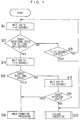
- step S4 the Polygonal motor control section 20 waits until a fourth time T4 (for example, 3 seconds) has elapsed. It is judged again in the step S5 whether or not the rotational speed of the Polygonal motor 15 is within the range of the target rotational speed (that is, the rotation stability signal is outputted). Consequently, it is confirmed whether the Polygonal motor 15 is stabilized at the target rotational speed. If it is judged that the rotational speed of the Polygonal motor 15 is the target rotational speed, image formation processing is started (step S6).
- the image formation processing is processing of, for example, driving the laser light source 1, driving the photoreceptor and supplying paper sheets.
- step S5 when it is judged in the step S5 that the rotational speed of the Polygonal motor 15 is not the target rotational speed, the Polygonal motor control section 20 waits for only a fifth time T5 (for example, 3 seconds) (step S7), after which it is judged again whether or not the rotational speed of the Polygonal motor 15 is the target rotational speed (step S8).
- step S7 a fifth time
- step S8 the failure processing is performed (step S10).
- step S6 the image formation processing.
- the rise time elapsed until the rotational speed of the Polygonal motor 15 reaches the target rotational speed is short, it is possible to quickly start the image forming operation. Even when the rise time becomes relatively longer due to the variations in the characteristics of the Polygonal motor 15 and the other components and the change with time, the image forming operation is performed, provided that the rotation of the Polygonal motor 15 can be stabilized. Consequently, it is possible to prevent a useless waiting time from being required before the image forming operation is started and prevent unnecessary failure processing from being performed.
- the rotational speed of the Polygonal motor 15 is the target rotational speed.
- the judgment in the step S2 is made every two seconds, and the judgment in the steps S5 and S8 is made at time intervals of 3 seconds. Consequently, the time required for the main control section 3 to perform the above described judgment processing may be significantly short. Therefore, the above described judgment processing does not impose the great burden on the main control section 3. Consequently, it is possible to carry out good control of the Polygonal motor 15 without imposing the great burden on the main control section 3.
- the failure processing is performed, assuming that an abnormality occurs in the laser scanner.
- the present invention is not limited to the above described embodiment.
Landscapes
- Engineering & Computer Science (AREA)
- Multimedia (AREA)
- Signal Processing (AREA)
- Physics & Mathematics (AREA)
- Power Engineering (AREA)
- General Physics & Mathematics (AREA)
- Optics & Photonics (AREA)
- Mechanical Optical Scanning Systems (AREA)
- Control Of Electric Motors In General (AREA)
- Laser Beam Printer (AREA)
Applications Claiming Priority (4)
| Application Number | Priority Date | Filing Date | Title |
|---|---|---|---|
| JP5209185A JP2832792B2 (ja) | 1993-08-24 | 1993-08-24 | モータ制御装置 |
| JP5209186A JPH0767373A (ja) | 1993-08-24 | 1993-08-24 | モータ制御装置 |
| JP209186/93 | 1993-08-24 | ||
| JP209185/93 | 1993-08-24 |
Publications (2)
| Publication Number | Publication Date |
|---|---|
| EP0641067A2 true EP0641067A2 (fr) | 1995-03-01 |
| EP0641067A3 EP0641067A3 (fr) | 1995-07-12 |
Family
ID=26517273
Family Applications (1)
| Application Number | Title | Priority Date | Filing Date |
|---|---|---|---|
| EP94113069A Withdrawn EP0641067A3 (fr) | 1993-08-24 | 1994-08-22 | Dispositif et méthode de contrÔle pour le démarrage d'un moteur. |
Country Status (2)
| Country | Link |
|---|---|
| US (1) | US5445017A (fr) |
| EP (1) | EP0641067A3 (fr) |
Cited By (2)
| Publication number | Priority date | Publication date | Assignee | Title |
|---|---|---|---|---|
| EP1289114A3 (fr) * | 2001-09-03 | 2004-01-14 | ABB Oy | Méthode pour modifier la vitesse d'un groupe de moteur |
| US7666413B2 (en) | 2000-10-12 | 2010-02-23 | Genetech, Inc. | Method of reducing viscosity of high concentration protein formulations |
Families Citing this family (1)
| Publication number | Priority date | Publication date | Assignee | Title |
|---|---|---|---|---|
| US6459443B1 (en) | 2001-06-21 | 2002-10-01 | Lexmark International, Inc | Method of minimizing print delay due to mirror motor warm-up in an electrophotographic machine |
Family Cites Families (12)
| Publication number | Priority date | Publication date | Assignee | Title |
|---|---|---|---|---|
| JPS5634475A (en) * | 1979-08-31 | 1981-04-06 | Canon Inc | Printer |
| JPS56163460A (en) * | 1980-05-20 | 1981-12-16 | Ricoh Co Ltd | Deciding method for constant-speed state |
| JPS59123481A (ja) * | 1982-12-29 | 1984-07-17 | Canon Inc | モ−タ制御装置 |
| US4796035A (en) * | 1984-11-30 | 1989-01-03 | Canon Kabushiki Kaisha | Image recording apparatus with improved system for feeding and exhausting recording sheets |
| GB2194693A (en) * | 1986-08-29 | 1988-03-09 | Rank Pullin Controls Ltd | Stepper motor drive apparatus |
| JP2792019B2 (ja) * | 1986-10-23 | 1998-08-27 | ミノルタ株式会社 | 画像形成装置における始動制御装置 |
| JPS63124786A (ja) * | 1986-11-14 | 1988-05-28 | Canon Inc | モ−タ制御装置 |
| JPS63220465A (ja) * | 1987-03-10 | 1988-09-13 | Mitsubishi Electric Corp | モ−タ制御回路 |
| JP2675811B2 (ja) * | 1988-04-20 | 1997-11-12 | キヤノン株式会社 | 光ビームプリンタ |
| US5206699A (en) * | 1988-05-06 | 1993-04-27 | Gersan Establishment | Sensing a narrow frequency band of radiation and gemstones |
| EP0343995B1 (fr) * | 1988-05-27 | 1994-07-20 | Tokyo Electric Co., Ltd. | Appareil de commande d'un moteur de balayage pour commander la vitesse de rotation d'un moteur de balayage |
| JP2899474B2 (ja) * | 1992-04-23 | 1999-06-02 | 東芝テック株式会社 | レーザスキャナ装置 |
-
1994
- 1994-08-12 US US08/289,228 patent/US5445017A/en not_active Expired - Fee Related
- 1994-08-22 EP EP94113069A patent/EP0641067A3/fr not_active Withdrawn
Cited By (3)
| Publication number | Priority date | Publication date | Assignee | Title |
|---|---|---|---|---|
| US7666413B2 (en) | 2000-10-12 | 2010-02-23 | Genetech, Inc. | Method of reducing viscosity of high concentration protein formulations |
| EP1289114A3 (fr) * | 2001-09-03 | 2004-01-14 | ABB Oy | Méthode pour modifier la vitesse d'un groupe de moteur |
| US7023169B2 (en) | 2001-09-03 | 2006-04-04 | Abb Oy | Method for changing speed of motor group |
Also Published As
| Publication number | Publication date |
|---|---|
| EP0641067A3 (fr) | 1995-07-12 |
| US5445017A (en) | 1995-08-29 |
Similar Documents
| Publication | Publication Date | Title |
|---|---|---|
| US5445017A (en) | Motor start examining device and method | |
| US5089848A (en) | Abnormal charge and toner density detecting system and method for use in an electrostatic copier | |
| US5105208A (en) | Image forming apparatus with good response motor servo control | |
| JPH03202368A (ja) | レーザ発振器の光量制御装置 | |
| JPH06255207A (ja) | ファンモータ故障検出手段を有する画像形成装置 | |
| JPH0767373A (ja) | モータ制御装置 | |
| JP2832792B2 (ja) | モータ制御装置 | |
| US5576536A (en) | Image forming apparatus including motor-driven rotary scanner and system for judging if motor rotation comes to steady state and for maintaining rotation at steady state | |
| US5448267A (en) | Laser beam printer having rotational control of image bearing member and deflecting device | |
| JP3604809B2 (ja) | 画像形成装置 | |
| US6211898B1 (en) | Optical scanning apparatus and devices including an optical scanning apparatus | |
| US6133840A (en) | Apparatus using vibration motor | |
| JPH0635333A (ja) | 画像形成装置 | |
| JPH0894948A (ja) | 記録装置 | |
| JP3466795B2 (ja) | 駆動装置およびこれを用いた複写機 | |
| JP2780182B2 (ja) | 原稿走査装置 | |
| JPH0553419A (ja) | 画像形成装置 | |
| JPH05300329A (ja) | 画像出力装置 | |
| EP0409184A2 (fr) | Système de traitement d'images | |
| JPH0193765A (ja) | 解像度測定装置 | |
| JPS60179732A (ja) | 光量制御装置 | |
| JPH11334139A (ja) | 画像形成装置及びその制御方法並びに記憶媒体 | |
| JPH0332159A (ja) | 画像処理装置 | |
| JPH08276616A (ja) | 画像形成装置 | |
| JPS62183669A (ja) | 画像処理装置の調整方法 |
Legal Events
| Date | Code | Title | Description |
|---|---|---|---|
| PUAI | Public reference made under article 153(3) epc to a published international application that has entered the european phase |
Free format text: ORIGINAL CODE: 0009012 |
|
| AK | Designated contracting states |
Kind code of ref document: A2 Designated state(s): DE FR GB IT |
|
| PUAL | Search report despatched |
Free format text: ORIGINAL CODE: 0009013 |
|
| AK | Designated contracting states |
Kind code of ref document: A3 Designated state(s): DE FR GB IT |
|
| 17P | Request for examination filed |
Effective date: 19950809 |
|
| 17Q | First examination report despatched |
Effective date: 19960528 |
|
| STAA | Information on the status of an ep patent application or granted ep patent |
Free format text: STATUS: THE APPLICATION HAS BEEN WITHDRAWN |
|
| 18W | Application withdrawn |
Withdrawal date: 19960917 |