EP0641277B1 - Verfahren zum formen von kunststoffgegenständen und so hergestellte gegenstände - Google Patents
Verfahren zum formen von kunststoffgegenständen und so hergestellte gegenstände Download PDFInfo
- Publication number
- EP0641277B1 EP0641277B1 EP93910174A EP93910174A EP0641277B1 EP 0641277 B1 EP0641277 B1 EP 0641277B1 EP 93910174 A EP93910174 A EP 93910174A EP 93910174 A EP93910174 A EP 93910174A EP 0641277 B1 EP0641277 B1 EP 0641277B1
- Authority
- EP
- European Patent Office
- Prior art keywords
- arcuate sections
- coupling element
- undercut
- formation
- closure member
- Prior art date
- Legal status (The legal status is an assumption and is not a legal conclusion. Google has not performed a legal analysis and makes no representation as to the accuracy of the status listed.)
- Expired - Lifetime
Links
- 238000000034 method Methods 0.000 title claims abstract description 27
- 238000000465 moulding Methods 0.000 title claims abstract description 17
- 239000004033 plastic Substances 0.000 title description 10
- 229920003023 plastic Polymers 0.000 title description 10
- 230000008878 coupling Effects 0.000 claims abstract description 106
- 238000010168 coupling process Methods 0.000 claims abstract description 106
- 238000005859 coupling reaction Methods 0.000 claims abstract description 106
- 230000015572 biosynthetic process Effects 0.000 claims abstract description 48
- 238000001746 injection moulding Methods 0.000 claims abstract description 10
- 239000002991 molded plastic Substances 0.000 claims description 10
- 206010021639 Incontinence Diseases 0.000 claims description 5
- 230000002093 peripheral effect Effects 0.000 claims description 5
- 238000000605 extraction Methods 0.000 claims description 2
- 238000004519 manufacturing process Methods 0.000 abstract description 5
- 238000005755 formation reaction Methods 0.000 description 27
- 239000000463 material Substances 0.000 description 13
- 230000013011 mating Effects 0.000 description 8
- 239000000853 adhesive Substances 0.000 description 7
- 230000001070 adhesive effect Effects 0.000 description 7
- 229920001200 poly(ethylene-vinyl acetate) Polymers 0.000 description 3
- 238000007789 sealing Methods 0.000 description 3
- 239000005038 ethylene vinyl acetate Substances 0.000 description 2
- 238000000926 separation method Methods 0.000 description 2
- 238000003466 welding Methods 0.000 description 2
- BHELIUBJHYAEDK-OAIUPTLZSA-N Aspoxicillin Chemical compound C1([C@H](C(=O)N[C@@H]2C(N3[C@H](C(C)(C)S[C@@H]32)C(O)=O)=O)NC(=O)[C@H](N)CC(=O)NC)=CC=C(O)C=C1 BHELIUBJHYAEDK-OAIUPTLZSA-N 0.000 description 1
- 229920000089 Cyclic olefin copolymer Polymers 0.000 description 1
- 239000004698 Polyethylene Substances 0.000 description 1
- 239000004743 Polypropylene Substances 0.000 description 1
- 230000001154 acute effect Effects 0.000 description 1
- 238000007796 conventional method Methods 0.000 description 1
- 229920001038 ethylene copolymer Polymers 0.000 description 1
- 239000011796 hollow space material Substances 0.000 description 1
- 238000002347 injection Methods 0.000 description 1
- 239000007924 injection Substances 0.000 description 1
- 229920001684 low density polyethylene Polymers 0.000 description 1
- 239000004702 low-density polyethylene Substances 0.000 description 1
- 238000012986 modification Methods 0.000 description 1
- 230000004048 modification Effects 0.000 description 1
- -1 polyethylene Polymers 0.000 description 1
- 229920000573 polyethylene Polymers 0.000 description 1
- 229920000098 polyolefin Polymers 0.000 description 1
- 229920005606 polypropylene copolymer Polymers 0.000 description 1
- 238000009877 rendering Methods 0.000 description 1
- 108010001894 stomadhesive Proteins 0.000 description 1
- 238000011477 surgical intervention Methods 0.000 description 1
- 239000002699 waste material Substances 0.000 description 1
Images



Classifications
-
- B—PERFORMING OPERATIONS; TRANSPORTING
- B29—WORKING OF PLASTICS; WORKING OF SUBSTANCES IN A PLASTIC STATE IN GENERAL
- B29C—SHAPING OR JOINING OF PLASTICS; SHAPING OF MATERIAL IN A PLASTIC STATE, NOT OTHERWISE PROVIDED FOR; AFTER-TREATMENT OF THE SHAPED PRODUCTS, e.g. REPAIRING
- B29C45/00—Injection moulding, i.e. forcing the required volume of moulding material through a nozzle into a closed mould; Apparatus therefor
- B29C45/17—Component parts, details or accessories; Auxiliary operations
- B29C45/40—Removing or ejecting moulded articles
- B29C45/44—Removing or ejecting moulded articles for undercut articles
- B29C45/4407—Removing or ejecting moulded articles for undercut articles by flexible movement of undercut portions of the articles
-
- A—HUMAN NECESSITIES
- A61—MEDICAL OR VETERINARY SCIENCE; HYGIENE
- A61F—FILTERS IMPLANTABLE INTO BLOOD VESSELS; PROSTHESES; DEVICES PROVIDING PATENCY TO, OR PREVENTING COLLAPSING OF, TUBULAR STRUCTURES OF THE BODY, e.g. STENTS; ORTHOPAEDIC, NURSING OR CONTRACEPTIVE DEVICES; FOMENTATION; TREATMENT OR PROTECTION OF EYES OR EARS; BANDAGES, DRESSINGS OR ABSORBENT PADS; FIRST-AID KITS
- A61F5/00—Orthopaedic methods or devices for non-surgical treatment of bones or joints; Nursing devices ; Anti-rape devices
- A61F5/44—Devices worn by the patient for reception of urine, faeces, catamenial or other discharge; Colostomy devices
- A61F5/445—Colostomy, ileostomy or urethrostomy devices
- A61F5/448—Means for attaching bag to seal ring
-
- B—PERFORMING OPERATIONS; TRANSPORTING
- B29—WORKING OF PLASTICS; WORKING OF SUBSTANCES IN A PLASTIC STATE IN GENERAL
- B29L—INDEXING SCHEME ASSOCIATED WITH SUBCLASS B29C, RELATING TO PARTICULAR ARTICLES
- B29L2031/00—Other particular articles
- B29L2031/56—Stoppers or lids for bottles, jars, or the like, e.g. closures
- B29L2031/565—Stoppers or lids for bottles, jars, or the like, e.g. closures for containers
Definitions
- This invention relates to a method of moulding plastics articles, according to the preamble of claim 1, and to a plastics closure member according to the preamble of claim 10 and a plastics coupling element comprising such an undercut formation according to the preamble of claim 18.
- Moulding undercut formations for example an internal flange around a circular lid or similar closure member, or around a ring coupling element, presents well known difficulties for injection moulding.
- the flange can be moulded by the use of an appropriately recessed core, but the radial extent of such a flange i.e. the amount of the undercut, must be relatively limited because of the need to extract the core from the moulding.
- conventional techniques require the undercut to have a chamfered or sloped surface which can produce a camming action to stretch the moulding to get the flange past the mould core projection which formed it.
- closure member or coupling element In moulding closure members and coupling elements from plastics materials, this need to have a chamfered or sloped surface can make the closure member or coupling element less secure and less positive, when for example, the closure member or coupling element is required to be a press fit over a lip on the external surface of a container or mating coupling element.
- DE-A-3110201 describes an apparatus for producing plastic caps by injection moulding, having a mould tool comprising a hollow mould body and a core projecting into this body, which core is arranged to be inserted in the mould body while maintaining the hollow space defining the cap, the core comprising three members arranged concentrically and having a common axis, of which the inner member and the outer member are rigidly arranged and the middle member is rotatable about the axis.
- GB-A-1,579,875 discloses a coupling for an ostomy bag.
- the invention aims to allow deeper undercuts which moreover do not need to be sloped, and to avoid the production of witness lines.
- a further object of the invention is to produce an improved closure member and an improved coupling element having a deeper undercut and a more secure closure and/or sealing action.
- the present invention provides a method of injection moulding an undercut formation on a circular body, wherein said formation is moulded in a series of arcuate sections alternating with spaces, and wherein the moulding core which produces the formation comprises an inner core member and an outer core member, and the core is extracted by firstly relatively rotating said body and said outer core member so that the body is expanded radially and then ejecting the body off the core.
- the invention thus provides a method according to claim 1 for forming moulded plastics article, and in particular a closure member or a coupling element, comprising an undercut formation on a circular body, said formation comprising a series of arcuate sections alternating with spaces, a plurality of the arcuate sections each having an undercut radially extending surface which subtends an angle to the axis of the body sufficient, in the case of a closure member or coupling element, to give a required degree of security to the article.
- the invention provides a moulded plastics closure member according to claim 10 comprising a circular body provided with an undercut formation, said formation comprising a series of arcuate sections alternating with spaces, ends of the respective arcuate sections being chamfered, the chamfered end surfaces of the arcuate sections being located at an angle of less than 60° to a tangent to the circular body, and a plurality of the arcuate sections each having an undercut radially extending surface which is disposed at an angle to the rotational axis of the body sufficient to give a required degree of security to the closure member.
- the moulded plastics closure member preferably comprises a circular body having an undercut formation and a seal on an internal wall above the undercut formation, said formation having a radial extent of greater than 0.005 inch (0.0125cm) and comprising a series of arcuate sections alternating with spaces, a plurality of the arcuate sections each having an undercut radially extending surface which subtends an angle to the axis of the body of at least 80° and sufficient to give a required degree of security to the closure member, the internal wall above the undercut formation being devoid of witness lines (as hereinbefore defined).
- the invention also provides a coupling element, and in particular a coupling element for use in an ostomy, incontinence, or wound care device, the element comprising an annular body provided with an undercut formation, said formation comprising a series of arcuate sections alternating with spaces, a plurality of the undercut arcuate sections each having a radially extending surface which is disposed at an angle to the rotational axis of the body sufficient to give a required degree of security to the coupling element.
- the undercut formation is discontinuous in a peripheral direction, but its radial extent can be greater than that achievable by conventional moulding techniques, and its radially extending surface can be at a steeper angle to the axis of the body.
- the arcuate sections of the undercut formation can be of equal or unequal length, depending upon the application. Usually they will be of equal length, but it is envisaged that, for example, a child resist closure member may have a series of arcuate sections of unequal length which cooperate with discontinuities in a lip of a container such that, in order to open the container, the closure member needs to be rotated relative to the container until the arcuate sections are in register with the appropriate discontinuities of the lip. This position can, for example, be indicated by aligning arrows on the closure member and the container respectively.
- the arcuate sections occupy as much of the periphery as possible, although for practical reasons, and in order to facilitate removal of the body from the core, preferably the ratio of the aggregate circumferential length of the spaces to the aggregate circumferential length of the arcuate sections is at least 1:3.
- the spaces themselves can be of equal or unequal length, depending upon the application.
- the radial extent of the undercut formation will depend on the application, and to an extent on the wall thickness of the body and the type of plastics material employed. However a radial extent of greater than 0.005 inch (0.0125 cm), and up to 0.020 inch (0.051 cm) or even more, can be achieved using the method of the invention in appropriate circumstances.
- the radial extent of the undercut formation and the thickness and material of the body need to be such as to permit relative rotation of the core and the body. This relative rotation causes the body to expand radially as the arcuate sections ride up on the core.
- the respective arcuate sections are chamfered and the chamfered end surfaces of the arcuate sections are not radially directed, but are located at an acute angle to a tangent to the circular body. Preferably the angle is less than 60°, most preferably less than 45°.
- the body can, if desired be rotated with respect to the core, however usually, the body will be held stationary and the core rotated by an amount sufficient to cause the arcuate sections to ride up out of the depressions in which they have been formed.
- the body can then easily be ejected from the core by any convenient means.
- each of the undercut arcuate sections has a radially extending surface which subtends an angle to the axis of the body sufficient to give the required degree of security thereto.
- This angle will usually be at least 70°, preferably 80°, and most preferably 90°. In some circumstances the angle may even exceed 90°, and extend to 95° or more, giving a slope opposite to that necessary using conventional moulding techniques.
- the invention provides the opportunity to obtain a closure or coupling assembly in which both the undercut formation on the closure member or coupling element and the lip on the component to which it is mated subtend a right angle to the axis of the closure assembly or coupling assembly without the presence of a witness line on an internal wall above the undercut formation.
- the closure member of the invention may find application in a wide variety of products where it is necessary to form an effective seal between two mating parts. It is particularly useful in those circumstances in which the undercut formation is required on a relatively small circular body, and in those closure members in which the undercut formation is on the inside of an annular ring member of U-shaped cross-section.
- the invention may be applied to a closure member for child-resist containers in accordance with claim 17, rendering the closure member more difficult to remove from the container as previously described.
- Improved security food containers represent a further application.
- Containers to which the closure members of the present invention may be applied are disclosed in US Patents Nos 3860133, 4434903, 3782574, and 3871662, UK Patent Application No. GB 2096108A and French Patent No. 2600977.
- This invention can also be embodied in a coupling element of an ostomy coupling in accordance with claims 18 and 26.
- Such couplings are used to attach a bag for receiving discharged material to a medical grade adhesive pad which is attached to the wearer's peristomal skin surface.
- ostomy coupling is described and claimed in GB-A-1571657.
- This includes a channel-section coupling element which co-operates with a second coupling element carrying a rib of closed-loop form which is designed to inter-engage with the channel of the first coupling element, so that a snap-fit is achieved between the two coupling elements.
- the channel section element is preferably attached to the bag but may be attached instead to the medical grade adhesive pad.
- the second element is preferably attached to the pad but may be attached to the bag.
- an undercut formation comprising a series of arcuate sections alternating with spaces is provided.
- a ring-like coupling element having a channel shape in cross section, defined by radially inner and outer walls and a floor, the element being characterised in that (i) the floor of the element has a plurality of depressions therein adjacent to the inner wall, the depressions being spaced around the channel, and (ii) the radially outer wall has a plurality of inwardly-projecting shelf-like roof portions, also spaced around the channel and extending partly across the channel from that part of the outer wall furthest from the channel floor.
- the security of attachment of the two coupling parts is enhanced by the overlap of the roof portions and the other coupling element; that is to say, the overlap of the roof portions tends to prevent the second (e.g. bag side) coupling element moving out of the channel in the axial direction of the coupling.
- the manufacture of the body side coupling element using injection moulding techniques is facilitated. It will be realised that the present invention provides the possibility for the use of more flexible side walls for the coupling element, enabling a lower application force to be used whilst providing a high degree of security by the use of an undercut formation with a steep angle of slope relative to the axis of the ostomy coupling element.
- the invention may be applied to a wide range of plastics materials, including for example, olefin polymers and co-polymers such as polyethylene, polypropylene, and ethylene co-polymers such as ethylene-vinyl acetate co-polymers.
- plastics materials including for example, olefin polymers and co-polymers such as polyethylene, polypropylene, and ethylene co-polymers such as ethylene-vinyl acetate co-polymers.
- Figure 1 shows one edge 11 of a circular lid member 10 in section with an inwardly turned flange 12 on the edge 11.
- the flange 12 projects by an amount p1 and its top surface slopes downwardly at an angle a.
- the lid mates with an outturned flange 15 on a cylindrical body 16.
- Flange 15 projects at right angles to the axis of the body 16.
- flange 15 gives no problem because the outer parts of the mould can be separate and move apart to release the moulded article. This is not possible with the internal core required to produce the flange 12 on lid member 10. In that case, the core must be forcibly pulled out and the edge 11 and flange 12 must stretch to allow this. Thus, the distance p1 is restricted and the angle ⁇ is a necessity in order that a camming action will occur between the mould core and the moulded article to stretch the article. It is apparent that lid 10 is not particularly secure on body 16, since a simple pull will separate the two.
- Figure 2 shows a similar view of a moulded lid which can be produced by the method according to the invention.
- Distance p2 can be greater, and ⁇ can be 0° or even a negative figure. With such a lid, the engagement of the two parts is much more secure since the mating surfaces 17, 18 of the flanges 12 and 15 will not allow them to separate easily.
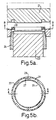
- FIGs 3, 4 and 5 show three stages in the release of the moulded part, in this case an undercut ring member 20.
- Four mould parts are required: a cavity member 21, a stripper member 22, an inner core member 23 and an outer core member 24.
- the latter is the one which includes the altered mould shape which defines the novel undercut flange.
- Figure 3a shows the stage when injection of moulding material has been completed and the article is ready for ejection.
- the shape of the outer core member 24 is seen clearly from Figures 3b and 3c.
- the groove 25 which forms the undercut flange 26 is discontinuous circumferentially.
- flange 26 is also discontinuous, but its surface 17 is not sloped.
- the ends 27 of the arcuate sections 28 and of the intervening spaces 29 of the flange 26 are however not radial but chamfered, as defined by the respective sections of groove 25.
- the sections 28 and the spaces 29 are of equal length.
- the cavity member 21 is first withdrawn ( Figure 4a). Then, the outer core member 24 is rotated (Figure 4b) by the amount ⁇ of one arcuate section 28. The chamfered ends 27 cam outwards against the ends of the groove 25 and the flange sections 28 ride up out of the groove ( Figure 4b). The ring 20 is then stretched outwards ( Figure 4a).
- the resultant lid or collar can have a greater degree of security when fitted to a mating member and is devoid of witness lines on the internal sealing wall 30.
- the lid, collar or other closure member can be made from a softer or thinner material making it easier to press fit the closure member to a mating member such as a lipped ring or cylinder to form a closure assembly. Notwithstanding the improved ease of assembly, a high degree of security is maintained.
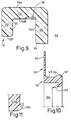
- Figures 6-11 these disclose the application of the invention to an ostomy coupling. It will normally be the case that the coupling element shown in Figure 6 will be the bag-side element and that shown in Figure 10 will be the body side element, but these elements may be reversed, that is, the Figure 6 element may be the body side and the Figure 10 element the bag-side, without departing from the invention.
- Mutually inter-engagable coupling elements designed according to the principles illustrated in Figure 6-11 may also be used as coupling elements in incontinence devices and in wound care appliances.
- a relatively thin pad of medical grade adhesive material is normally attached at one of its surfaces to the skin of the wearer and at the other of its surfaces to the surface 163 shown in figure 10.
- Such a pad may have a stomal orifice therein or may have provision whereby its central portion can be pushed out or detached, so that waste material being discharged from the body of the wearer can pass into an ostomy bag or an incontinence device which is connected by the bag side coupling element 110 to the body side coupling element 160.
- Suitable materials for such an adhesive pad include, for example, those described by Chen in US Patent 3,339,546; by Chen et al in US Patent No. 4,192,785; by Pawelchak et al in US Patent No. 4,393080; and by Doyle et al in US Patent No. 4,551,490.
- a particularly suitable material is that sold under the Registered Trade Mark STOMAHESIVE by Bristol-Myers Squibb of Ickenham, Middlesex, England.
- a bag side coupling element according to the invention is illustrated. It comprises a channel section element 110 of circular form seen in Figure 6.
- the female ostomy coupling element may be normally made of a synthetic plastics material such as EVA.
- EVA Grade UL 00209 is one material, available from Esso, which is suitable.
- the male element may be made of low density polyethylene.
- the element 110 as seen in Figure 6 has tabs 110A, 110B and 110C.
- the tabs 110A and 110B are provided to facilitate attachment of a belt, and the tab 110C is provided to afford a grasping point whereby the wearer may separate the two coupling elements by "peeling" them apart.
- the coupling element 110 has a radially outer wall 112 and a radially inner wall 114.
- the wall 114 surrounds a stomal orifice 118 at the centre of the coupling.
- the generally ring-like or annular element 110 has a floor 116 which joins the radially inner and outer walls 112, 114, this floor having a surface 116A to which may be attached, e.g.
- an ostomy bag provided with a suitable hole in one of its walls to serve as an entry for discharges from the wearer.
- This entry hole is aligned with the stomal orifice 118 as is conventional in ostomy bags.
- the floor 116 has a surface 116B at the base of the channel, and, into this floor, there are provided a plurality of recesses 120.
- These recesses 120 in their presently preferred form are relatively shallow, flat bottomed, and are equally spaced peripherally around the coupling element. As seen best in Figure 8, the recesses 120 have a shape which is approximately rectangular. The recesses, however, could be differently shaped according to the design of the moulding equipment, if desired.
- each such recesses there are 24 such recesses, spaced around the ring at 15° centres.
- the depth of each such recess is approximately 0.01 inch, i.e. approximately 0.254 millimetres.
- the remainder of the surface 116B at the base of the channel is substantially flat.
- the recesses serve to receive one or more mould core members, for example inner core member 23 in Figures 3a-5a, and serve, in extraction of the annular body from the mould, to prevent rotation of said body relative to the said mould core member.
- the radially outer wall 112 is provided with a plurality of radially inwardly projecting roof-like portions 130 (also referred to herein as arcuate sections) whose undersides 132 (i.e. top surfaces as seen in Fig. 7, which are undersides of the portions 130 when the female coupling element is laid flat on a horizontal surface) are substantially flat and extend substantially in a plane parallel to the planes of the respective surfaces 116A and 116B.
- the portion 130 extends inwardly a distance such that it covers from about 10 to about 20%, and preferably about 15%, of the width of the channel as will be discussed later. In moulding terms, the portions 130 define undercut formations.
- the roof-like portions 130 may have radially inner surfaces defined by respective continuous curves 134 that extend from the end 112B of the wall 112 in a smooth curve to merge with the surface 132. In a peripheral sense, as seen in Figures 6 and 8 the walls 134 curve smoothly to merge with the radially inner surface 112A of the wall 112. This structure is provided so that the portions 130 are forced outwardly by rotation of the core, as described above, so permitting the coupling element to be readily removed from the mould.
- the radially inner wall 114 is, as seen in Figure 7, of greater height than the wall 112, and has its radially outer corner radiused as seen at 136.
- the surfaces 134 and 136 contribute to the ease with which a counterpart coupling element such as is seen in Figure 10 can be pushed into an inter-engaged condition, relative to the coupling element 110.
- the respective roof portions 130 are equally spaced around the inner periphery of the wall 112, and are preferably located at 45° centres. Other spacings, however, may be used.
- the extent in a peripheral sense of each roof portion 130 is such that it occupies an arc subtending at the axis of revolution of the coupling element, i.e. at the centre in the case of a geometrically circular ostomy coupling element, an angle of between 15 and 25°, preferably between about 18 and 22°.
- the number, positioning, and angular extent of the roof portions 130 may be varied. Preferably there are 6, 8, 10 or 12 of the roof portions, and the roof portions are preferably equally angularly spaced in a peripheral sense around the coupling element.
- the roof portions 130 may extend inwardly of the wall 112 by an amount of up to half the width of the channel, although preferably they extend by an amount equal to about one tenth to one fifth, more preferably one seventh to one fifth, and, most preferably one sixth, of the width of the channel measured in a radial direction.
- Figure 10 illustrates, in partial cross-section, an ostomy coupling element 160, which is also of ring-like or annular form and intended to interfit with the element 110.
- the element 160 would be the body side coupling element. It comprises a radially extending substantially flat flange 162 and a peripherally extending rib member 165 formed for mutual inter-engagement with coupling element 110.
- the flange 162 has a surface 163 to which is secured, in any suitable manner, a pad (not shown) of medical grade adhesive material.
- the rib member 165 has a radially outer rim 167 and a radially inner flexible deflectable seal strip 168.
- the purpose of the strip 168 is to assure good sealing between the two coupling elements when they are inter-engaged.
- the rim 167 has a shaped surface 166, located at substantially 45° to the plane of the flange 162. Of course other angular values may be employed but about 45° is preferred.
- the edges of the roof portions 130 engage the surface 166 at peripherally spaced locations.
- the seal strip 168 is deflected slightly radially outwardly and bears resiliently against the surface 114A of the wall 114, so providing a good seal and taking up any minor tolerance variations which may have arisen in manufacture.
Landscapes
- Health & Medical Sciences (AREA)
- Engineering & Computer Science (AREA)
- Veterinary Medicine (AREA)
- General Health & Medical Sciences (AREA)
- Nursing (AREA)
- Biomedical Technology (AREA)
- Heart & Thoracic Surgery (AREA)
- Vascular Medicine (AREA)
- Life Sciences & Earth Sciences (AREA)
- Mechanical Engineering (AREA)
- Manufacturing & Machinery (AREA)
- Public Health (AREA)
- Orthopedic Medicine & Surgery (AREA)
- Epidemiology (AREA)
- Animal Behavior & Ethology (AREA)
- Orthopedics, Nursing, And Contraception (AREA)
- Moulds For Moulding Plastics Or The Like (AREA)
- Processing And Handling Of Plastics And Other Materials For Molding In General (AREA)
- Containers Having Bodies Formed In One Piece (AREA)
- Injection Moulding Of Plastics Or The Like (AREA)
- Materials For Medical Uses (AREA)
- Closures For Containers (AREA)
- Slide Fasteners, Snap Fasteners, And Hook Fasteners (AREA)
- Toys (AREA)
- Casting Or Compression Moulding Of Plastics Or The Like (AREA)
Claims (30)
- Verfahren zum Spritzgießen einer Formation an einem kreisförmigen Körper (20), bei dem der Gußkern, mit Hilfe dessen die Formation hergestellt wird, ein inneres Kernbauteil (23) und ein äußeres Kernbauteil (24) aufweist, dadurch gekennzeichnet, daß die Formation eine hinterschnittene Formation ist, die als eine Reihe von gekrümmten Abschnitten (28) geformt ist, die sich mit Zwischenräumen (29) abwechseln, und daß der Kern herausgezogen wird, indem zuerst der Körper (20) und das äußere Kernbauteil (24) relativ gedreht werden, so daß der Körper (20) durch eine Eingriffswirkung zwischen dem Kern (23, 24) und den gekrümmten Abschnitten (28) in radialer Richtung aufgeweitet und dann der Körper von dem Kern abgestoßen wird.
- Verfahren nach Anspruch 1, dadurch gekennzeichnet, daß die hinterschnittende Formation an einem Verschlußbauteil oder einem Kopplungselement geformt wird.
- Verfahren nach Anspruch 1 oder 2, dadurch gekennzeichnet, daß die gekrümmten Abschnitte (28) der hinterschnittenen Formation von gleicher Länge sind.
- Verfahren nach einem der vorhergehenden Ansprüche, dadurch gekennzeichnet, daß das Verhältnis der gesamten Umfangslänge der Zwischenräume (29) zu der gesamten Umfangslänge der gekrümmten Abschnitte (28) zumindest 1:3 beträgt.
- Verfahren nach einem der Ansprüche 1 bis 4, dadurch gekennzeichnet, daß die Zwischenräume (29) von gleicher Länge sind.
- Verfahren nach einem der vorhergehenden Ansprüche, dadurch gekennzeichnet, daß die radiale Erstreckung der hinterschnittenen Formation größer als 0,005 Zoll (0,0125 cm) beträgt.
- Verfahren nach einem der vorhergehenden Ansprüche, dadurch gekennzeichnet, daß die Enden (27) der jeweiligen gekrümmten Abschnitte (28) abgeschrägt sind.
- Verfahren nach einem der vorhergehenden Ansprüche, dadurch gekennzeichnet, daß der kreisförmige Körper (20) stationär gehalten und das äußere Kernbauteil (24) um einen Betrag gedreht wird, der ausreichend ist, um zu bewirken, daß die gekrümmten Abschnitte (28) aus den Vertiefungen (25), in denen sie geformt wurden, herausrutschen.
- Verfahren nach einem der vorhergehenden Ansprüche, dadurch gekennzeichnet, daß jeder der gekrümmten Abschnitte (28) eine hinterschnittene, sich radial erstreckende Fläche hat, die mit einem Winkel von mindestens 80° zur Achse des kreisförmigen Körpers verläuft.
- Geformtes Kunststoff-Verschlußbauteil, das durch ein Verfahren nach einem der Ansprüche 1 bis 9 herstellbar ist, mit einem kreisförmigen Körper, der mit einer hinterschnittenen Formation (26) versehen ist, wobei die Formation eine Reihe von gekrümmten Abschnitten (28) aufweist, die sich mit Zwischenräumen (29) abwechseln, dadurch gekennzeichnet, daß die Enden (27) der jeweiligen gekrümmten Abschnitte (28) abgeschrägt sind und die abgeschrägten Endflächen der gekrümmten Abschnitte mit einem Winkel von weniger als 60° zu einer Tangente des kreisförmigen Körpers (20) angeordnet sind, und daß jeder aus einer Anzahl von den hinterschnittenen, gekrümmten Abschnitten (28) eine sich radial erstreckende Fläche (17) hat, die mit einem Winkel zu der Drehachse des Körpers verläuft, der ausreichend ist, um dem Verschlußbauteil ein ausreichendes Maß an Sicherheit zu verleihen.
- Geformtes Kunststoff-Verschlußbauteil nach Anspruch 10, dadurch gekennzeichnet, daß es eine Innenwand (30) über der hinterschnittenen Formation (26) aufweist, die Formation eine radiale Erstreckung von mehr als 0,005 Zoll (0,0125 cm) hat, eine Anzahl von den hinterschnittenen, gekrümmten Abschnitten (28) jeweils eine sich radial erstreckende Fläche (17) hat, die mit einem Winkel von zumindest 80° zu der Drehachse des Körpers verläuft und ausreichend ist, um dem Verschlußbauteil ein ausreichendes Maß an Sicherheit zu verleihen, wobei die Innenwand (30) über der hinterschnittenden Formation keine Markierungslinien hat.
- Geformtes Kunststoff-Verschlußbauteil nach Anspruch 10 oder 11, dadurch gekennzeichnet, daß die gekrümmten Abschnitte (28) der hinterschnittenen Formation (26) von gleicher Länge sind.
- Geformtes Kunststoff-Verschlußbauteil nach Anspruch 10 oder 11, dadurch gekennzeichnet, daß die gekrümmten Abschnitte der hinterschnittenen Formation von ungleicher Länge sind.
- Geformtes Kunststoff-Verschlußbauteil nach einem der Ansprüche 10 bis 13, dadurch gekennzeichnet, daß das Verhältnis der gesamten Umfangslänge der Zwischenräume (29) zu der gesamten Umtangslänge der gekrümmten Abschnitte (28) mindestens 1:3 beträgt.
- Geformtes Kunststoff-Verschlußbauteil nach einem der Ansprüche 10 bis 14, dadurch gekennzeichnet, daß die Zwischenräume (29) von gleicher Länge sind.
- Geformtes Kunststoff-Verschlußbauteil nach einem der Ansprüche 10 bis 15, dadurch gekennzeichnet, daß es zur Verwendung mit einem kindersicheren Behälter ausgestaltet ist.
- Kindersicherer Behälter mit einem Verschlußbauteil nach Anspruch 16, dadurch gekennzeichnet, daß das Verschlußbauteil eine Reihe von gekrümmten Abschnitten von ungleicher Länge hat, die mit Unterbrechungen in einer Lippe des Behälters zusammenwirken, so daß das Verschlußbauteil zum Öffnen des Behälters relativ zu dem Behälter gedreht werden muß, bis sich die gekrümmten Abschnitte mit den passenden Unterbrechungen der Lippe in Ausrichtung befinden.
- Kopplungselement (110) zur Verwendung bei einer Ostomie-, Inkontinenz- oder Wundpflegeeinrichtung, wobei das Element einen ringförmigen Körper mit einer fortlaufenden Umfangswand aufweist, die mit einer hinterschnittenen Formation versehen ist, wobei die Formation eine Reihe von hinterschnittenen, gekrümmten Abschnitten (130), die sich mit Zwischenräumen abwechseln, aufweist, dadurch gekennzeichnet, daß eine Anzahl der hinterschnittenen, gekrümmten Abschnitte (130) jeweils eine sich radial erstreckende Fläche (132) aufweist, die mit einem Winkel zu der Achse des Körpers verläuft, der ausreichend ist, um dem Kopplungselement bezüglich dessen Anbringung an dem gegenwirkenden Preßsitz-Kopplungselement (160) ein ausreichendes Maß an Sicherheit zu verleihen.
- Kopplungselement nach Anspruch 18, bei dem eine Einschnapppassung mit dem gegenwirkenden Preßsitz-Kopplungselement (160) erreicht wird.
- Kopplungselement nach Anspruch 18, bei dem, wenn das Kopplungselement an dem gegenwirkenden Preßsitz-Kopplungselement befestigt wird, ein hörbares Klicken zu hören ist.
- Kopplungselement nach Anspruch 18, dadurch gekennzeichnet, daß die gekrümmten Abschnitte (130) in einer Umfangsrichtung mit gleichem Winkel beabstandet sind und jeweils einen Winkel einnehmen, der einem Winkel von 25 und 15° an der Drehachse der Kopplung gegenüberliegt.
- Kopplungselement nach Anspruch 18 oder 21, dadurch gekennzeichnet, daß 6, 8, 10 oder 12 dieser gekrümmten Abschnitte vorgesehen sind.
- Kupplungselement nach einem Ansprüche 18, 21 und 22, dadurch gekennzeichnet, daß der ringförmige Körper, wenn er im radialen Querschnitt betrachtet wird, kanalförmig ist, und daß sich die gekrümmten Abschnitte (130) von der Außenwand des Kanals über eine Distanz von bis zu der Hälfte der Breite des Kanals in radialer Richtung nach innen erstrecken.
- Kopplungselement nach einem der Ansprüche 18 und 21 bis 23, dadurch gekennzeichnet, daß es durch Spritzgießen geformt ist und daß in der Basisfläche (116B) des Kanals eine Anzahl von flachen Vertiefungen (120) vorgesehen ist, die dazu dienen, um ein oder mehrere Formkernbauteile aufzunehmen.
- Kopplungselement nach Anspruch 24, dadurch gekennzeichnet, daß die Vertiefungen (120) beim Herausziehen des ringförmigen Körpers aus der Form dazu dienen, eine Drehung des Körpers relativ zu dem Formkernbauteil zu verhindern.
- Kopplung zur Verwendung bei einer Ostomie-, Wundpflege- oder Inkontinenzeinrichtung, wobei die Kopplung zwei miteinander eingreifbare Kopplungselemente (110, 160) aufweist, dadurch gekennzeichnet, daß ein Kopplungselement eines nach einem der Ansprüche 18 bis 23 ist, und das andere Kopplungselement eine ringförmige Rippe (165) aufweist, die einen flexiblen, elastischen und biegsamen Dichtungsstreifen (168) daran hat, der angeordnet ist, um mit einer Wand (114A) des ringförmigen Kanals zusammenzuwirken, um ein Auslecken von Körperausscheidungen zu verhindern.
- Kopplung nach Anspruch 26, dadurch gekennzeichnet, daß das Kopplungselement (110), das den ringförmigen Kanal enthält, das beutelseitige Element ist, und daß (116), das die Rippe enthält, das körperseitige Element ist.
- Kopplungselement (110) nach Anspruch 18, bei dem das Element einen ringförmigen Körper mit einer fortlaufenden Umfangswand (112) hat, die mit einer hinterschnittenen Formation versehen ist, dadurch gekennzeichnet, daß die Formation eine Reihe von gekrümmten Abschnitten (130) aufweist, die sich mit Zwischenräumen abwechseln, daß eine Anzahl der hinterschnittenen, gekrümmten Abschnitte jeweils eine sich radial erstreckende Fläche (132) hat, die mit einem Winkel zu der Drehachse des Körpers verläuft, der ausreichend ist, um der Vorrichtung ein ausreichendes Maß an Sicherheit zu verleihen, und daß sich die sich radial erstreckende Fläche über eine Distanz radial nach innen oder nach außen, wie der Fall sein kann, erstreckt, so daß eine ausreichende Überlappung mit einem zusammenwirkenden Preßsitz-Kopplungselement (160) der Vorrichtung bewirkt wird, um so die beiden Kopplungselemente sicher miteinander zu verbinden.
- Kopplungselement nach Anspruch 28, dadurch gekennzeichnet, daß die Überlappung so ist, daß die beiden Kopplungselemente der Vorrichtung durch eine Abschälbewegung aber nicht durch direktes Abziehen voneinander getrennt werden können.
- Ringähnliches Kopplungselement einer Ostomie-Kopplung mit einem kanalförmigen Querschnitt, der durch radial verlaufende Innen- und Außenwände (112, 114) und einen Boden (116) gebildet ist, wobei das Element dadurch gekennzeichnet ist, daß (i) der Boden des Elementes benachbart zu der Innenwand eine Anzahl von darin ausgebildeten Vertiefungen (120) hat, die Vertiefungen um den Kanal herum beabstandet sind, und daß (ii) die radial verlaufende Außenwand fortlaufend ist und eine Anzahl von nach innen gerichtet vorstehenden, plattenähnlichen Dachbereichen (130) hat, die ebenfalls um den Kanal herum beabstandet sind und sich teilweise von dem Teil der Außenwand, der am weitesten von dem Kanalboden entfernt ist, über den Kanal erstrecken.
Priority Applications (3)
| Application Number | Priority Date | Filing Date | Title |
|---|---|---|---|
| EP04076728A EP1473002B1 (de) | 1992-05-12 | 1993-05-10 | Ostomiekupplung |
| ES04076728T ES2304579T3 (es) | 1992-05-12 | 1993-05-10 | Acoplamiento de ostomia. |
| EP99203112A EP1223022B1 (de) | 1992-05-12 | 1993-05-10 | Verfahren zum Formen von Kunststoffgegenständen und so hergestellte Gegenstände |
Applications Claiming Priority (5)
| Application Number | Priority Date | Filing Date | Title |
|---|---|---|---|
| GB9210186 | 1992-05-12 | ||
| GB929210186A GB9210186D0 (en) | 1992-05-12 | 1992-05-12 | Method of moulding |
| GB9223225 | 1992-11-05 | ||
| GB929223225A GB9223225D0 (en) | 1992-05-12 | 1992-11-05 | Method of moulding plastics articles |
| PCT/GB1993/000959 WO1993023229A1 (en) | 1992-05-12 | 1993-05-10 | Method of moulding plastics articles and articles produced thereby |
Related Child Applications (1)
| Application Number | Title | Priority Date | Filing Date |
|---|---|---|---|
| EP99203112A Division EP1223022B1 (de) | 1992-05-12 | 1993-05-10 | Verfahren zum Formen von Kunststoffgegenständen und so hergestellte Gegenstände |
Publications (2)
| Publication Number | Publication Date |
|---|---|
| EP0641277A1 EP0641277A1 (de) | 1995-03-08 |
| EP0641277B1 true EP0641277B1 (de) | 2000-04-19 |
Family
ID=26300866
Family Applications (3)
| Application Number | Title | Priority Date | Filing Date |
|---|---|---|---|
| EP93910174A Expired - Lifetime EP0641277B1 (de) | 1992-05-12 | 1993-05-10 | Verfahren zum formen von kunststoffgegenständen und so hergestellte gegenstände |
| EP04076728A Revoked EP1473002B1 (de) | 1992-05-12 | 1993-05-10 | Ostomiekupplung |
| EP99203112A Revoked EP1223022B1 (de) | 1992-05-12 | 1993-05-10 | Verfahren zum Formen von Kunststoffgegenständen und so hergestellte Gegenstände |
Family Applications After (2)
| Application Number | Title | Priority Date | Filing Date |
|---|---|---|---|
| EP04076728A Revoked EP1473002B1 (de) | 1992-05-12 | 1993-05-10 | Ostomiekupplung |
| EP99203112A Revoked EP1223022B1 (de) | 1992-05-12 | 1993-05-10 | Verfahren zum Formen von Kunststoffgegenständen und so hergestellte Gegenstände |
Country Status (14)
| Country | Link |
|---|---|
| US (1) | US5693036A (de) |
| EP (3) | EP0641277B1 (de) |
| JP (3) | JP3428989B2 (de) |
| AT (3) | ATE392198T1 (de) |
| AU (1) | AU677192B2 (de) |
| CA (1) | CA2135604C (de) |
| DE (3) | DE69328427T2 (de) |
| DK (3) | DK1473002T3 (de) |
| ES (3) | ES2304579T3 (de) |
| FI (1) | FI109187B (de) |
| NO (2) | NO944310L (de) |
| NZ (2) | NZ299115A (de) |
| PT (1) | PT1473002E (de) |
| WO (1) | WO1993023229A1 (de) |
Families Citing this family (26)
| Publication number | Priority date | Publication date | Assignee | Title |
|---|---|---|---|---|
| CA2146791C (en) * | 1994-04-29 | 2002-06-25 | Robert S. Herrmann | Sliding refrigerator shelf assembly |
| GB2296662B (en) * | 1995-01-03 | 1998-09-23 | Squibb & Sons Inc | Ostomy coupling |
| GB2298794A (en) * | 1995-03-09 | 1996-09-18 | Squibb & Sons Inc | Ostomy coupling with intervening support ring |
| US7097544B1 (en) * | 1995-10-27 | 2006-08-29 | Applied Materials Inc. | Chemical mechanical polishing system having multiple polishing stations and providing relative linear polishing motion |
| CA2186656C (en) * | 1996-08-20 | 2007-11-06 | Peter Leslie Steer | An ostomy coupling |
| JP3190289B2 (ja) | 1997-10-06 | 2001-07-23 | アイシン化工株式会社 | アキュムレータ |
| WO1999030653A1 (en) * | 1997-12-18 | 1999-06-24 | Bristol-Myers Squibb Company | Convex insert system for an ostomy appliance |
| US5947941A (en) * | 1998-03-05 | 1999-09-07 | Hollister Incorporated | Two-piece ostomy appliance |
| GB2344998A (en) | 1998-12-22 | 2000-06-28 | Bristol Myers Squibb Co | Ostomy coupling |
| US6673056B2 (en) | 2001-11-05 | 2004-01-06 | Hollister Incorporated | Snap-in insert for convex ostomy faceplate |
| US6960316B2 (en) * | 2002-10-30 | 2005-11-01 | Sorensen Research And Development Trust | Injection-molded plastic container or closure with turned-under rim and method of injection-molding same |
| US8016816B2 (en) * | 2003-09-09 | 2011-09-13 | Convatec Technologies Inc. | Fecal management appliance and method and apparatus for introducing same |
| US7727188B2 (en) * | 2003-12-17 | 2010-06-01 | Convatec Technologies Inc. | Balloon catheter with positioning pocket |
| JP5307976B2 (ja) * | 2006-08-22 | 2013-10-02 | 池上金型工業株式会社 | 射出成形金型 |
| DE102009034715A1 (de) * | 2009-07-24 | 2011-01-27 | Martin Ruda | Spritzgusswerkzeug, Verfahren zum Spritzgießen eines Spritzgussbauteils sowie Verschluss- und/oder Anschlusseinrichtung eines Spritzpistolenfarbbechers |
| US8641956B1 (en) | 2010-11-03 | 2014-02-04 | George Roy Payton | Gasket for a molded part and method of manufacture and use |
| US8529245B1 (en) | 2010-11-03 | 2013-09-10 | George Roy Payton | Undercut mold insert |
| US8945076B2 (en) | 2011-08-03 | 2015-02-03 | Hollister Incorporated | Ostomy appliance with integrated belt tabs |
| JP5925601B2 (ja) * | 2012-05-30 | 2016-05-25 | 株式会社足立ライト工業所 | 射出成形方法および射出成形用金型 |
| HUE062325T2 (hu) * | 2012-10-23 | 2023-10-28 | Coloplast As | Osztómiás tasak |
| CN103409829B (zh) * | 2013-07-30 | 2016-03-16 | 苏州豪建纺织有限公司 | 一种高渗透熔丝结构 |
| WO2015157236A1 (en) | 2014-04-11 | 2015-10-15 | Silgan White Cap LLC | Metal closure with low pressure engagement lugs |
| US20170327277A1 (en) * | 2016-05-10 | 2017-11-16 | Snapple Beverage Corp. | Container assemblies including metal closures and thermoplastic containers and methods of hot-filling food and beverage products |
| GB201806045D0 (en) * | 2018-04-12 | 2018-05-30 | Ostomycure As | Lid |
| CN109262988B (zh) * | 2018-09-06 | 2023-09-01 | 临海伟星新型建材有限公司 | 一种用于弯头管件的自动脱模模具 |
| CN116214857B (zh) * | 2023-02-16 | 2023-08-04 | 浙江博创机械有限公司 | 一种高效率注塑机 |
Family Cites Families (26)
| Publication number | Priority date | Publication date | Assignee | Title |
|---|---|---|---|---|
| US3339546A (en) * | 1963-12-13 | 1967-09-05 | Squibb & Sons Inc | Bandage for adhering to moist surfaces |
| US3782574A (en) * | 1970-08-20 | 1974-01-01 | R Rumble | Tamperproof closure for containers |
| US3860133A (en) | 1973-01-26 | 1975-01-14 | Pauls James D | Safety cap |
| US3871662A (en) | 1974-01-11 | 1975-03-18 | Owens Illinois Inc | Child-resistant closure |
| DE2638619C3 (de) * | 1976-08-27 | 1980-11-13 | G. Bauknecht Gmbh, 7000 Stuttgart | Spritzgießform zum Herstellen eines Spritzgußteiles mit einer Hinterschneidung |
| NZ186585A (en) * | 1977-03-30 | 1981-03-16 | Kingsdown Medical Consultants | Coupling for joining pad or dressing to an ostomy bag |
| GB1579875A (en) * | 1977-03-30 | 1980-11-26 | Kingsdown Medical Consultants | Coupling for an ostomy bag |
| GB1571657A (en) * | 1977-03-30 | 1980-07-16 | Kingsdown Medical Consultants | Ostomy bag |
| US4192785A (en) * | 1977-06-08 | 1980-03-11 | E. R. Squibb & Sons, Inc. | Ostomy adhesive |
| US4257526A (en) * | 1978-08-21 | 1981-03-24 | Coors Container Company | Bottle closure and finish |
| US4320230A (en) * | 1979-09-24 | 1982-03-16 | Exxon Research & Engineering Co. | Methanol homologation using iron-cobalt carbonyl cluster catalyst |
| GB2096108A (en) | 1981-02-19 | 1982-10-13 | Plaspharm Uk Ltd | Removing snap-fit caps |
| DE3110201A1 (de) * | 1981-03-17 | 1982-09-30 | Wolfgang 4800 Bielefeld Suttner | "vorrichtung zum herstellen von kunststoffkappen im spritzgussverfahren" |
| US4393080A (en) * | 1981-12-24 | 1983-07-12 | E. R. Squibb & Sons, Inc. | Adhesive compositions |
| US4434903A (en) | 1982-11-22 | 1984-03-06 | Cooke Carl W | Safety closure and container |
| US4551490A (en) * | 1983-06-27 | 1985-11-05 | E. R. Squibb & Sons, Inc. | Adhesive composition resistant to biological fluids |
| IT1187213B (it) * | 1985-11-07 | 1987-12-16 | Bormioli Metalplast Spa | Coperchio-bicchiere di sicurezza |
| AU584962B2 (en) * | 1985-11-21 | 1989-06-08 | Futuraprodukter Hb | Fixing device for stomy bag |
| FR2600977B1 (fr) | 1986-07-07 | 1988-09-09 | Novembal Sa | Dispositif de fermeture de protection pour flacons, bouteilles ou recipients analogues |
| AU600000B2 (en) * | 1986-07-31 | 1990-08-02 | E.R. Squibb & Sons, Inc. | Ostomy coupling |
| AU601194B2 (en) * | 1986-07-31 | 1990-09-06 | E.R. Squibb & Sons, Inc. | Ostomy coupling |
| FR2613613B1 (fr) * | 1987-04-10 | 1990-12-07 | Biotrol Sa Lab | Dispositif d'assemblage pour poche d'ostomie |
| GB2205041A (en) * | 1987-05-22 | 1988-11-30 | Craig Med Prod Ltd | Ostomy coupling |
| US4820285A (en) * | 1987-09-16 | 1989-04-11 | E.R. Squibb & Sons, Inc. | Bayonet coupling for ostomy device |
| GB2225951B (en) * | 1988-12-13 | 1992-06-24 | Squibb & Sons Inc | Ostomy coupling |
| GB2227667B (en) * | 1989-02-03 | 1992-07-29 | Squibb & Sons Inc | Ostomy coupling |
-
1993
- 1993-05-10 AT AT04076728T patent/ATE392198T1/de active
- 1993-05-10 DE DE69328427T patent/DE69328427T2/de not_active Expired - Lifetime
- 1993-05-10 DE DE69333705T patent/DE69333705T2/de not_active Revoked
- 1993-05-10 DK DK04076728T patent/DK1473002T3/da active
- 1993-05-10 WO PCT/GB1993/000959 patent/WO1993023229A1/en not_active Ceased
- 1993-05-10 PT PT04076728T patent/PT1473002E/pt unknown
- 1993-05-10 EP EP93910174A patent/EP0641277B1/de not_active Expired - Lifetime
- 1993-05-10 NZ NZ299115A patent/NZ299115A/en not_active IP Right Cessation
- 1993-05-10 ES ES04076728T patent/ES2304579T3/es not_active Expired - Lifetime
- 1993-05-10 JP JP51997993A patent/JP3428989B2/ja not_active Expired - Lifetime
- 1993-05-10 EP EP04076728A patent/EP1473002B1/de not_active Revoked
- 1993-05-10 AT AT99203112T patent/ATE282516T1/de not_active IP Right Cessation
- 1993-05-10 NZ NZ252226A patent/NZ252226A/en not_active IP Right Cessation
- 1993-05-10 DE DE69334214T patent/DE69334214T2/de not_active Revoked
- 1993-05-10 US US08/335,839 patent/US5693036A/en not_active Expired - Lifetime
- 1993-05-10 AT AT93910174T patent/ATE191878T1/de not_active IP Right Cessation
- 1993-05-10 AU AU40782/93A patent/AU677192B2/en not_active Expired
- 1993-05-10 EP EP99203112A patent/EP1223022B1/de not_active Revoked
- 1993-05-10 CA CA002135604A patent/CA2135604C/en not_active Expired - Lifetime
- 1993-05-10 DK DK93910174T patent/DK0641277T3/da active
- 1993-05-10 ES ES93910174T patent/ES2147755T3/es not_active Expired - Lifetime
- 1993-05-10 ES ES99203112T patent/ES2230798T3/es not_active Expired - Lifetime
- 1993-05-10 DK DK99203112T patent/DK1223022T3/da active
-
1994
- 1994-11-11 FI FI945307A patent/FI109187B/fi not_active IP Right Cessation
- 1994-11-11 NO NO944310A patent/NO944310L/no unknown
-
1999
- 1999-03-25 NO NO19991450A patent/NO322483B1/no not_active IP Right Cessation
-
2003
- 2003-02-05 JP JP2003028877A patent/JP3621399B2/ja not_active Expired - Lifetime
-
2004
- 2004-07-08 JP JP2004202311A patent/JP4388865B2/ja not_active Expired - Lifetime
Also Published As
Similar Documents
| Publication | Publication Date | Title |
|---|---|---|
| US5693036A (en) | Method of injection moulding an undercut formation on a circular body and a closure assembly including a coupling element | |
| EP1407731B1 (de) | Ostomiekupplung | |
| EP1013250B1 (de) | Ostomiekupplung | |
| EP0347068B1 (de) | Kupplung für Ostomiebeutel | |
| JPH0459903B2 (de) | ||
| JPH0430112Y2 (de) | ||
| EP0650709B1 (de) | Ostomiekupplung | |
| WO1996006016A1 (en) | Containers with decorative covers | |
| EP0257802B1 (de) | Ostomiekupplung | |
| GB2219507A (en) | An ostomy bag coupling | |
| AU2003248477B2 (en) | Ostomy coupling | |
| JPH066048Y2 (ja) | 合成樹脂製ピルファープルーフキャップ | |
| AU684121B2 (en) | Ostomy coupling | |
| GB2299510A (en) | Ostomy coupling | |
| NZ270388A (en) | Ostomy coupling; stretchable ring of one coupling element can be shifted by manual pressure between a locking position and an unlocking position | |
| MXPA00000121A (en) | Ostomy coupling |
Legal Events
| Date | Code | Title | Description |
|---|---|---|---|
| PUAI | Public reference made under article 153(3) epc to a published international application that has entered the european phase |
Free format text: ORIGINAL CODE: 0009012 |
|
| 17P | Request for examination filed |
Effective date: 19941212 |
|
| AK | Designated contracting states |
Kind code of ref document: A1 Designated state(s): AT BE CH DE DK ES FR GB GR IE IT LI LU MC NL PT SE |
|
| 17Q | First examination report despatched |
Effective date: 19960905 |
|
| GRAG | Despatch of communication of intention to grant |
Free format text: ORIGINAL CODE: EPIDOS AGRA |
|
| GRAG | Despatch of communication of intention to grant |
Free format text: ORIGINAL CODE: EPIDOS AGRA |
|
| GRAG | Despatch of communication of intention to grant |
Free format text: ORIGINAL CODE: EPIDOS AGRA |
|
| GRAH | Despatch of communication of intention to grant a patent |
Free format text: ORIGINAL CODE: EPIDOS IGRA |
|
| GRAH | Despatch of communication of intention to grant a patent |
Free format text: ORIGINAL CODE: EPIDOS IGRA |
|
| GRAH | Despatch of communication of intention to grant a patent |
Free format text: ORIGINAL CODE: EPIDOS IGRA |
|
| GRAH | Despatch of communication of intention to grant a patent |
Free format text: ORIGINAL CODE: EPIDOS IGRA |
|
| GRAA | (expected) grant |
Free format text: ORIGINAL CODE: 0009210 |
|
| AK | Designated contracting states |
Kind code of ref document: B1 Designated state(s): AT BE CH DE DK ES FR GB GR IE IT LI LU MC NL PT SE |
|
| PG25 | Lapsed in a contracting state [announced via postgrant information from national office to epo] |
Ref country code: GR Free format text: LAPSE BECAUSE OF NON-PAYMENT OF DUE FEES Effective date: 20000419 Ref country code: AT Free format text: LAPSE BECAUSE OF FAILURE TO SUBMIT A TRANSLATION OF THE DESCRIPTION OR TO PAY THE FEE WITHIN THE PRESCRIBED TIME-LIMIT Effective date: 20000419 |
|
| REF | Corresponds to: |
Ref document number: 191878 Country of ref document: AT Date of ref document: 20000515 Kind code of ref document: T |
|
| REG | Reference to a national code |
Ref country code: CH Ref legal event code: EP |
|
| PGFP | Annual fee paid to national office [announced via postgrant information from national office to epo] |
Ref country code: AT Payment date: 20000525 Year of fee payment: 8 |
|
| REF | Corresponds to: |
Ref document number: 69328427 Country of ref document: DE Date of ref document: 20000525 |
|
| REG | Reference to a national code |
Ref country code: IE Ref legal event code: FG4D |
|
| ITF | It: translation for a ep patent filed | ||
| PG25 | Lapsed in a contracting state [announced via postgrant information from national office to epo] |
Ref country code: PT Free format text: LAPSE BECAUSE OF FAILURE TO SUBMIT A TRANSLATION OF THE DESCRIPTION OR TO PAY THE FEE WITHIN THE PRESCRIBED TIME-LIMIT Effective date: 20000719 |
|
| ET | Fr: translation filed | ||
| REG | Reference to a national code |
Ref country code: CH Ref legal event code: NV Representative=s name: TROESCH SCHEIDEGGER WERNER AG |
|
| REG | Reference to a national code |
Ref country code: DK Ref legal event code: T3 |
|
| REG | Reference to a national code |
Ref country code: ES Ref legal event code: FG2A Ref document number: 2147755 Country of ref document: ES Kind code of ref document: T3 |
|
| PLBE | No opposition filed within time limit |
Free format text: ORIGINAL CODE: 0009261 |
|
| STAA | Information on the status of an ep patent application or granted ep patent |
Free format text: STATUS: NO OPPOSITION FILED WITHIN TIME LIMIT |
|
| 26N | No opposition filed | ||
| PGFP | Annual fee paid to national office [announced via postgrant information from national office to epo] |
Ref country code: LU Payment date: 20010510 Year of fee payment: 9 |
|
| PGFP | Annual fee paid to national office [announced via postgrant information from national office to epo] |
Ref country code: MC Payment date: 20010531 Year of fee payment: 9 |
|
| REG | Reference to a national code |
Ref country code: GB Ref legal event code: IF02 |
|
| PG25 | Lapsed in a contracting state [announced via postgrant information from national office to epo] |
Ref country code: MC Free format text: LAPSE BECAUSE OF NON-PAYMENT OF DUE FEES Effective date: 20020510 Ref country code: LU Free format text: LAPSE BECAUSE OF NON-PAYMENT OF DUE FEES Effective date: 20020510 |
|
| GRAG | Despatch of communication of intention to grant |
Free format text: ORIGINAL CODE: EPIDOS AGRA |
|
| REG | Reference to a national code |
Ref country code: GB Ref legal event code: 732E |
|
| BECA | Be: change of holder's address |
Owner name: CONVATEC TECHNOLOGIES INC.6100 NEIL ROAD, SUITE 50 Effective date: 20090302 |
|
| BECH | Be: change of holder |
Owner name: CONVATEC TECHNOLOGIES INC.6100 NEIL ROAD, SUITE 50 Effective date: 20090302 |
|
| REG | Reference to a national code |
Ref country code: CH Ref legal event code: PUE Owner name: CONVATEC TECHNOLOGIES INC. Free format text: E.R. SQUIBB & SONS, L.L.C.#LAWRENCEVILLE-PRINCETON ROAD#PRINCETON, NJ 08540 (US) -TRANSFER TO- CONVATEC TECHNOLOGIES INC.#3993 HOWARD HUGHES PARKWAY SUITE 250#LAS VEGAS, NV 89169-6754 (US) Ref country code: CH Ref legal event code: PFA Owner name: E.R. SQUIBB & SONS, L.L.C. Free format text: E.R. SQUIBB & SONS, INC.#345 PARK AVENUE#NEW YORK, NY 10154-0037 (US) -TRANSFER TO- E.R. SQUIBB & SONS, L.L.C.#LAWRENCEVILLE-PRINCETON ROAD#PRINCETON, NJ 08540 (US) |
|
| REG | Reference to a national code |
Ref country code: NL Ref legal event code: TD Effective date: 20100303 Ref country code: NL Ref legal event code: SD Effective date: 20100303 |
|
| REG | Reference to a national code |
Ref country code: FR Ref legal event code: TP Ref country code: FR Ref legal event code: CD |
|
| PGFP | Annual fee paid to national office [announced via postgrant information from national office to epo] |
Ref country code: CH Payment date: 20120514 Year of fee payment: 20 Ref country code: NL Payment date: 20120515 Year of fee payment: 20 Ref country code: DK Payment date: 20120510 Year of fee payment: 20 Ref country code: DE Payment date: 20120502 Year of fee payment: 20 Ref country code: IE Payment date: 20120510 Year of fee payment: 20 |
|
| PGFP | Annual fee paid to national office [announced via postgrant information from national office to epo] |
Ref country code: FR Payment date: 20120608 Year of fee payment: 20 Ref country code: SE Payment date: 20120511 Year of fee payment: 20 Ref country code: BE Payment date: 20120514 Year of fee payment: 20 Ref country code: GB Payment date: 20120509 Year of fee payment: 20 |
|
| PGFP | Annual fee paid to national office [announced via postgrant information from national office to epo] |
Ref country code: IT Payment date: 20120516 Year of fee payment: 20 |
|
| PGFP | Annual fee paid to national office [announced via postgrant information from national office to epo] |
Ref country code: ES Payment date: 20120607 Year of fee payment: 20 |
|
| REG | Reference to a national code |
Ref country code: DE Ref legal event code: R071 Ref document number: 69328427 Country of ref document: DE |
|
| REG | Reference to a national code |
Ref country code: DK Ref legal event code: EUP |
|
| REG | Reference to a national code |
Ref country code: NL Ref legal event code: V4 Effective date: 20130510 Ref country code: CH Ref legal event code: PL |
|
| REG | Reference to a national code |
Ref country code: GB Ref legal event code: PE20 Expiry date: 20130509 |
|
| BE20 | Be: patent expired |
Owner name: CONVATEC TECHNOLOGIES INC. Effective date: 20130510 |
|
| REG | Reference to a national code |
Ref country code: ES Ref legal event code: FD2A Effective date: 20130725 |
|
| PG25 | Lapsed in a contracting state [announced via postgrant information from national office to epo] |
Ref country code: GB Free format text: LAPSE BECAUSE OF EXPIRATION OF PROTECTION Effective date: 20130509 Ref country code: DE Free format text: LAPSE BECAUSE OF EXPIRATION OF PROTECTION Effective date: 20130511 |
|
| PG25 | Lapsed in a contracting state [announced via postgrant information from national office to epo] |
Ref country code: ES Free format text: LAPSE BECAUSE OF EXPIRATION OF PROTECTION Effective date: 20130511 |
|
| REG | Reference to a national code |
Ref country code: IE Ref legal event code: MK9A |
|
| PG25 | Lapsed in a contracting state [announced via postgrant information from national office to epo] |
Ref country code: IE Free format text: LAPSE BECAUSE OF EXPIRATION OF PROTECTION Effective date: 20130510 |