EP0642008B1 - Vorrichtung zum Antrieb einer Messspindel einer Auswuchtmaschine - Google Patents
Vorrichtung zum Antrieb einer Messspindel einer Auswuchtmaschine Download PDFInfo
- Publication number
- EP0642008B1 EP0642008B1 EP94107054A EP94107054A EP0642008B1 EP 0642008 B1 EP0642008 B1 EP 0642008B1 EP 94107054 A EP94107054 A EP 94107054A EP 94107054 A EP94107054 A EP 94107054A EP 0642008 B1 EP0642008 B1 EP 0642008B1
- Authority
- EP
- European Patent Office
- Prior art keywords
- friction wheel
- electric motor
- rotor
- motion unit
- measuring spindle
- Prior art date
- Legal status (The legal status is an assumption and is not a legal conclusion. Google has not performed a legal analysis and makes no representation as to the accuracy of the status listed.)
- Expired - Lifetime
Links
- 230000001133 acceleration Effects 0.000 claims description 12
- 230000005540 biological transmission Effects 0.000 claims description 2
- 230000006835 compression Effects 0.000 description 6
- 238000007906 compression Methods 0.000 description 6
- 238000005259 measurement Methods 0.000 description 3
- 230000000694 effects Effects 0.000 description 2
- 230000003247 decreasing effect Effects 0.000 description 1
- 238000000034 method Methods 0.000 description 1
- 230000036316 preload Effects 0.000 description 1
- 239000000725 suspension Substances 0.000 description 1
Images
Classifications
-
- G—PHYSICS
- G01—MEASURING; TESTING
- G01M—TESTING STATIC OR DYNAMIC BALANCE OF MACHINES OR STRUCTURES; TESTING OF STRUCTURES OR APPARATUS, NOT OTHERWISE PROVIDED FOR
- G01M1/00—Testing static or dynamic balance of machines or structures
- G01M1/02—Details of balancing machines or devices
- G01M1/06—Adaptation of drive assemblies for receiving the body to be tested
Definitions
- the invention relates to a device according to Preamble of claim 1.
- the object of the invention is to provide a device to create the preamble of claim 1, in which the drive connection between motor-driven Friction wheel and the measuring spindle of the balancing machine without the help of an additional facility is achieved.
- the friction wheel which forms a movement unit with the electric motor, is by a when accelerating the rotor (Rotor) of the electric motor generated torque in brought the drive position. Immediately after Turning on the electric motor comes this torque to the effect, so that the friction wheel immediately after switching on is brought into the drive position.
- This Torque is generated due to a force which on the movement unit when accelerating the Electric motor rotor and friction wheel at a distance of one offset to the axis of the rotor or rotor of the Storage facility supported by the electric motor on the machine frame the movement unit attacks.
- the storage facility forms a pivot axis around which the Torque comes into effect.
- the spindle can do this be rotatably connected to a drive wheel which is the friction wheel driven by the electric motor is pressed by the generated torque.
- the Torque is generated as long as the rotor (rotor) of the electric motor is accelerated.
- the Rotor of the electric motor acts on the movement unit a force around that of the bearing device defined swivel axis. In this way becomes an automatic establishment of the drive connection between that driven by the electric motor Friction wheel and the measuring spindle manufactured.
- This connection is affected by the frictional engagement
- Counter moments which occur during the acceleration of the the rotor attached to the measuring spindle, e.g. Motor vehicle wheel, arise, supported or with upright receive.
- a friction lining on the friction wheel can provide support and / or on a rotationally fixedly connected to the measuring spindle Drive wheel act.
- Between the friction wheel and the electric motor can a gearbox for speed reduction or translation should be provided.
- the friction wheel is rigid or non-rotatable with the Rotor of the electric motor is connected.
- the movement unit formed by the electric motor and friction wheel can be stored on the machine frame in this way be that the drive connection between the friction wheel and the measuring spindle at the end of the acceleration, d. H. for example when the rotor of the electric motor rotates with constant or decreasing speed is solved automatically because there is no acceleration of the rotor (rotor) of the electric motor and resulting loss of transmission forces on the movement unit no force around that of the bearing device formed pivot axis and Friction between spindle and friction wheel no counter torque work more.
- the movement unit consisting of an electric motor and friction wheel moves in from the drive position their rest position, in which no drive connection between friction wheel and spindle, due to the now missing force with which the movement unit brought into the drive position and has been held.
- the rest position the movement unit to be kept in balance. This can be done take place that the movement unit like a Pendulum is stored in the storage facility.
- the Weight of the movement unit is then in the storage facility, which acts as a self-aligning bearing, balanced.
- weight balancer in the form of one on the machine frame supported spring may be provided, which in the absence of Acceleration of the rotor of the electric motor and thus the friction wheel the movement unit in the Rest position, i.e. except drive connection with the Measuring spindle brings.
- the invention thus makes an automatic movement of the friction wheel in the drive position and on automatic removal of the friction wheel from the drive position, for example when you reach one desired final speed.
- the electric motor can be switched off when the final speed is reached or earlier and can continue to run after uncoupling.
- the drive device can advantageously are used in such balancing machines at which the unbalance measurement in the outlet of the measuring spindle, i.e. when the spindle is decoupled from the drive, such as that described, for example, in US Pat. No. 4,480,472 is.
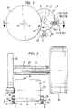
- a measuring spindle 9 shown in FIGS. 1 to 3 is in a known manner in a measuring spindle bearing 20th stored in a balancing machine.
- a rotor 19 e.g. a motor vehicle wheel, in known manner rotatably clamped on the measuring spindle 9.
- a drive wheel is rotationally fixed with the measuring spindle 9 10 connected.
- the Measuring spindle 9 rotated about its spindle axis 25. Of the The measuring spindle 9 is driven with the aid of following described drive device.
- the drive device has an electric motor 1. With a rotor (rotor) not shown in detail of the electric motor 1 is via an output shaft 26 a friction wheel 2 rotatably connected. For translation or reduction can be between friction wheel 2 and motor rotor also be a gearbox.
- the friction wheel 2 and the electric motor 1 form a movement unit 8.
- This movement unit 8 can consist of one in the 1 is shown with solid lines rest position, in which the friction wheel 2 is out of engagement with the drive wheel 10 is in a drive position, which are shown in dash-dotted lines in FIG. 1 is to be brought. In the drive position exists between the friction wheel 2 and the drive wheel 10 a frictional connection. Friction wheel 2 and / or drive wheel 10 can be equipped with a friction lining.
- the weight is balanced Movement unit 8 by a on the machine frame 3rd supported spring 11 reached.
- On the machine frame 3 is the movement unit 8 via a storage device, which forms a pivot axis 24 is supported.
- the pivot axis 24 is of journals 12 and 13 formed, which is attached to the housing of the electric motor 1 are.
- the pivot axis 24 extends parallel to axis 23 of the rotor (rotor) of the electric motor 1.
- the journals 12 and 13 are in journal guides 14 and 15 (Fig. 2) stored.
- the pin guides 14 and 15 form linear guides for the Bearing journals 12 and 13 and thus for the swivel axis 24.
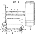
- bearings 6 and 7 are also provided.
- One bearing 6 is in the same Formed like the two bearings 4 and 5 in the exemplary embodiment of FIG. 2.
- the journal 27 is linearly movable performed, as in the journals 12 and 13 of the 2 is the case.
- a Compression spring 18 mediates in the direction of the frictional engagement a preload between friction wheel 2 and drive wheel 10.
- a bearing pivot 21 formed for the movement unit 8.
- Bearing pivot 21 runs the pivot axis 24.
- Der Bearing pivot point 21 is formed by a bearing ball 28, which are movably supported in a machine frame 3 Ball holder 29 is mounted.
- Friction wheel 2 and drive wheel 10 The friction between Friction wheel 2 and drive wheel 10 is carried out by a between counter torque acting on these two components. This counter moment is during the entire acceleration phase the rotor of the electric motor 1 maintained. This counter moment arises from the acceleration of the driven system (rotor 19, spindle 9, drive wheel 10). During the frictional engagement between friction wheel 2 and drive wheel 10 by the compression springs 16 and 17 (embodiment 2) or by the compression spring 18 (embodiment 3) a constant pressing force guaranteed between friction wheel 2 and drive wheel 10.
- the direction of action of the compression springs 16, 17 and 18 is approximately in a plane in which the axis of rotation of the driving friction wheels 2, which in the illustrated Embodiments with the axis of rotation 23 of the Rotor of the electric motor 1 coincides, and the Rotation axis 25 of the measuring spindle 9 and the pivot axis 24 lie.
- the movement unit 8, e.g. the housing of the electric motor 1 are in the acceleration phase at a stop 32.
- the measuring spindle 9 moves in the outlet.
- the unbalance measurement process in a known manner, for example, as explained in U.S. Patent 4,480,472 is carried out, the unbalance measurement process.
Landscapes
- Physics & Mathematics (AREA)
- General Physics & Mathematics (AREA)
- Testing Of Balance (AREA)
- Connection Of Motors, Electrical Generators, Mechanical Devices, And The Like (AREA)
Description
- Fig. 1:
- in schematischer Darstellung eine Seitenansicht eines Ausführungsbeispiels eines Meßspindelantriebs einer Auswuchtmaschine;
- Fig. 2:
- eine Ansicht der in Fig. 1 dargestellten Vorrichtung in der Schnittlinie II-II der Fig. 1; und
- Fig. 3:
- ein weiteres Ausführungsbeispiel eines Meßspindelantriebs.
Claims (17)
- Vorrichtung zum Antrieb einer Meßspindel (9) einer Auswuchtmaschine mit einem Reibrad (2), das von einem einen Rotor aufweisenden Elektromotor (1) angetrieben ist und zusammen mit dem Elektromotor (1) eine an einem Maschinenrahmen (3) befestigte Einheit bildet, wobei das Reibrad (2) durch ein bei beschleunigtem Rotor des Elektromotors (1) erzeugtes Drehmoment mit der Meßspindel (9) in Antriebsverbindung und außer Antriebsverbindung bringbar ist,
dadurch gekennzeichnet,
daß die aus Elektromotor (1) und Reibrad (2) bestehende Einheit als Bewegungseinheit (8) ausgebildet ist, die um eine Schwenkachse (24) einer am Maschinenrahmen (3) angeordneten Lagereinrichtung (4, 5; 6, 7), welche gegenüber der Rotorachse (23) des Elektromotors (1) versetzt angeordnet ist, bewegbar abgestützt ist, so daß durch das bei beschleunigtem Rotor des Elektromotors (1) erzeugte Drehmoment die Bewegungseinheit (8) zur Herstellung der Antriebsverbindung zwischen dem Reibrad (2) und der Meßspindel (9) auf die Meßspindel (9) zu bewegt ist. - Vorrichtung nach Anspruch 1, dadurch gekennzeichnet, daß die Bewegungseinheit (8) in der Weise am Maschinenrahmen (3) gelagert ist, daß die Antriebsverbindung zwischen dem Reibrad (2) und der Meßspindel (9) durch Beendigung der Beschleunigung des Rotors des Elektromotors (1) selbsttätig gelöst ist.
- Vorrichtung nach Anspruch 1 oder 2, dadurch gekennzeichnet, daß aufgrund eines bei der Kraftübertragung am Reibschluß zwischen Reibrad (2) und Meßspindel (9) bzw. einem mit der Meßspindel (9) drehfest verbundenem Antriebsrad (10) entstehenden Gegenmoments der Reibschluß aufrecht erhalten ist.
- Vorrichtung nach einem der Ansprüche 1 bis 3, dadurch gekennzeichnet, daß in der Beschleunigungsphase die Bewegungseinheit (8) an einem Anschlag (32) anliegt.
- Vorrichtung nach einem der Ansprüche 1 bis 4, dadurch gekennzeichnet, daß die Bewegungseinheit (8) durch eine Gewichtsausgleichseinrichtung in der Ruheposition im Gleichgewicht gehalten ist.
- Vorrichtung nach Anspruch 5, dadurch gekennzeichnet, daß die Gewichtsausgleichseinrichtung als am Maschinenrahmen (3) abgestützte Feder (11) ausgebildet ist.
- Vorrichtung nach einem der Ansprüche 1 bis 6, dadurch gekennzeichnet, daß die Bewegungseinheit (8) in der Lagereinrichtung (4, 5; 6, 7) gegenüber dem Maschinenrahmen (3) federnd gelagert ist.
- Vorrichtung nach einem der Ansprüche 1 bis 7, dadurch gekennzeichnet, daß die Lagereinrichtung (4, 5; 6, 7) zwei Lagerstellen aufweist.
- Vorrichtung nach Anspruch 8, dadurch gekennzeichnet, daß die Bewegungseinheit (8) in wenigstens einer Lagerstelle federnd gelagert ist.
- Vorrichtung nach einem der Ansprüche 1 bis 9, dadurch gekennzeichnet, daß die Bewegungseinheit (8) in der Lagereinrichtung (4, 5; 6, 7) schwenkbar gelagert ist.
- Vorrichtung nach einem der Ansprüche 1 bis 10, dadurch gekennzeichnet, daß die in der Lagereinrichtung (4, 5; 6, 7) gebildete Schwenkachse (24) parallel zur Rotorachse (23) liegt.
- Vorrichtung nach einem der Ansprüche 1 bis 11, dadurch gekennzeichnet, daß die Bewegungseinheit (8) in einer Lagerstelle (7) um einen Lagerdrehpunkt (21) und in einer anderen Lagerstelle (6) geradlinig geführt ist.
- Vorrichtung nach einem der Ansprüche 1 bis 11, dadurch gekennzeichnet, daß die Bewegungseinheit (8) in beiden Lagerstellen (4, 5) geradlinig geführt ist.
- Vorrichtung nach Anspruch 12 oder 13, dadurch gekennzeichnet, daß die geradlinige Führung der Bewegungseinheit (8) im wesentlichen in einer Ebene erfolgt, in welcher die Drehachse (25) der Meßspindel (9) und die Achse des in Antriebsposition befindlichen Reibrades (2) liegen.
- Vorrichtung nach einem der Ansprüche 1 bis 14, dadurch gekennzeichnet, daß die Achse des Reibrades (2) und die Rotorachse (23) des Elektromotors (1) zusammenfallen.
- Vorrichtung nach einem der Ansprüche 1 bis 15, dadurch gekennzeichnet, daß das Reibrad (2) drehfest mit dem Rotor des Elektromotors (1) verbunden ist.
- Vorrichtung nach einem der Ansprüche 1 bis 16, dadurch gekennzeichnet, daß die Bewegungseinheit (8) mit in Richtung der Antriebsverbindung zwischen Reibrad (2) und Meßspindel (9) wirkender Federvorspannung in der Lagereinrichtung (4, 5; 6, 7) gelagert ist.
Applications Claiming Priority (2)
| Application Number | Priority Date | Filing Date | Title |
|---|---|---|---|
| DE4329831A DE4329831C2 (de) | 1993-09-03 | 1993-09-03 | Vorrichtung zum Antrieb einer Meßspindel einer Auswuchtmaschine |
| DE4329831 | 1993-09-03 |
Publications (3)
| Publication Number | Publication Date |
|---|---|
| EP0642008A2 EP0642008A2 (de) | 1995-03-08 |
| EP0642008A3 EP0642008A3 (de) | 1996-11-27 |
| EP0642008B1 true EP0642008B1 (de) | 1999-02-24 |
Family
ID=6496793
Family Applications (1)
| Application Number | Title | Priority Date | Filing Date |
|---|---|---|---|
| EP94107054A Expired - Lifetime EP0642008B1 (de) | 1993-09-03 | 1994-05-05 | Vorrichtung zum Antrieb einer Messspindel einer Auswuchtmaschine |
Country Status (6)
| Country | Link |
|---|---|
| US (1) | US5717138A (de) |
| EP (1) | EP0642008B1 (de) |
| JP (1) | JP2652520B2 (de) |
| AT (1) | ATE176950T1 (de) |
| DE (1) | DE4329831C2 (de) |
| ES (1) | ES2130301T3 (de) |
Families Citing this family (8)
| Publication number | Priority date | Publication date | Assignee | Title |
|---|---|---|---|---|
| US6430992B1 (en) * | 1998-09-02 | 2002-08-13 | Snap-On Technologies, Inc. | Device for measuring the forces generated by a rotor Imbalance |
| DE10160955B4 (de) * | 2001-12-12 | 2020-07-16 | Snap-On Equipment Gmbh | Verfahren und Vorrichtung zum Eindrehen eines an einer Auswuchtmaschine drehgelagerten und mittels eines Elektromotors antreibbaren Rotors, insbesondere Kraftfahrzeugrades |
| ITRE20020073A1 (it) * | 2002-10-02 | 2004-04-03 | Corghi Spa | Macchina equilibratrice. |
| US20050038580A1 (en) * | 2003-08-15 | 2005-02-17 | Seim Kerri Jean | Information about structural integrity of vehicles |
| JP5035755B2 (ja) * | 2008-03-28 | 2012-09-26 | 株式会社Ihi | 基準加振機 |
| CN103411732B (zh) * | 2013-08-22 | 2015-07-15 | 孝感松林国际计测器有限公司 | 不平衡超差下机自动锁机的动平衡测量装置及其使用方法 |
| DE102015210773A1 (de) * | 2015-06-12 | 2016-12-15 | Schaeffler Technologies AG & Co. KG | Generatorsystem für Schienenfahrzeuge |
| CN118408678B (zh) * | 2024-06-05 | 2025-01-07 | 山东沃尔鑫机械有限公司 | 一种推土铲压轴的振动检测仪及其检测方法 |
Family Cites Families (9)
| Publication number | Priority date | Publication date | Assignee | Title |
|---|---|---|---|---|
| US3772919A (en) * | 1972-02-09 | 1973-11-20 | Hunter Eng Co | Balancing apparatus for rotating bodies and method of producing frequency stable phase delay |
| US3889542A (en) * | 1973-11-09 | 1975-06-17 | Fmc Corp | Wheel mounting apparatus |
| DE3010315A1 (de) * | 1980-03-18 | 1981-09-24 | Carl Schenck Ag, 6100 Darmstadt | Maschine zur optimierung des laufverhaltens von reifen bzw. raedern |
| US4435982A (en) * | 1981-02-20 | 1984-03-13 | Balco, Inc. | Machine and method for balancing wheels |
| JPS57141526A (en) * | 1981-02-25 | 1982-09-01 | Mitsubishi Electric Corp | Compensating device for detected torque of electric dynamometer |
| US4480472A (en) * | 1982-08-10 | 1984-11-06 | Hofmann Corporation Automotive Service Equipment | Electronic wheel balancer for vehicle wheels |
| JPH0227524A (ja) * | 1988-07-14 | 1990-01-30 | Nec Corp | 垂直磁気記録膜の製造方法 |
| JPH0743631Y2 (ja) * | 1988-08-11 | 1995-10-09 | 株式会社工技研究所 | ホイールバランサーの回転駆動装置 |
| US5355728A (en) * | 1992-06-22 | 1994-10-18 | Balance Technology, Inc. | Tire balance measuring machine for various tire sizes |
-
1993
- 1993-09-03 DE DE4329831A patent/DE4329831C2/de not_active Expired - Fee Related
-
1994
- 1994-05-05 ES ES94107054T patent/ES2130301T3/es not_active Expired - Lifetime
- 1994-05-05 EP EP94107054A patent/EP0642008B1/de not_active Expired - Lifetime
- 1994-05-05 AT AT94107054T patent/ATE176950T1/de not_active IP Right Cessation
- 1994-08-26 JP JP6202541A patent/JP2652520B2/ja not_active Expired - Lifetime
-
1996
- 1996-02-06 US US08/597,689 patent/US5717138A/en not_active Expired - Fee Related
Also Published As
| Publication number | Publication date |
|---|---|
| EP0642008A3 (de) | 1996-11-27 |
| ATE176950T1 (de) | 1999-03-15 |
| JP2652520B2 (ja) | 1997-09-10 |
| DE4329831C2 (de) | 1998-07-23 |
| JPH07174657A (ja) | 1995-07-14 |
| DE4329831A1 (de) | 1995-03-09 |
| ES2130301T3 (es) | 1999-07-01 |
| US5717138A (en) | 1998-02-10 |
| EP0642008A2 (de) | 1995-03-08 |
Similar Documents
| Publication | Publication Date | Title |
|---|---|---|
| EP0921946B2 (de) | Zylinderantrieb | |
| DE10202897B4 (de) | Vorrichtung und Verfahren zum Messen einer Unwucht eines Motorrad-Rades | |
| DE102022207743A1 (de) | Unwuchtmesseinrichtung, Bearbeitungseinrichtung, sowie Verfahren zur Bearbeitung eines Werkstücks | |
| DE69709599T2 (de) | Vorrichtung zur automatischen Verriegelung von Rädern und dergleichen auf einer Auswuchtmaschine | |
| EP0278037B1 (de) | Maschine zum Wuchtzentrieren von Umlaufkörpern | |
| DE4329831C2 (de) | Vorrichtung zum Antrieb einer Meßspindel einer Auswuchtmaschine | |
| DE68906496T2 (de) | Schwungradvorrichtung mit Torsionsdämpfer. | |
| DE2225120C3 (de) | Auswuchtvorrichtung zum Ausgleich von rotierenden Maschinenteilen, insbesondere Schleifscheiben | |
| EP0771648B1 (de) | Vorrichtung zur Spielbeseitigung in einem Druckwerk | |
| DE102021101012A1 (de) | Schweißvorrichtung zum Reibschweißen, insbesondere zum Zirkularreibschweißen, von Kunststoffen | |
| DE602005002391T2 (de) | Schwenkbarer Drehtisch | |
| DE2937819A1 (de) | Unterflurradsatzdrehmaschine | |
| EP0250963B1 (de) | Vorrichtung zum Antrieb eines schwingenden Vorgreifers einer Druckmaschine | |
| WO2024156789A2 (de) | Unwuchtmesseinrichtung, bearbeitungseinrichtung, sowie verfahren zur kalibrierung der bearbeitungseinrichtung, insbesondere der unwuchtmesseinrichtung | |
| DE3307445C2 (de) | Verfahren zum Reibschweißen von Teilen | |
| EP0037428A1 (de) | Unwuchtrüttler mit Schaltkupplung | |
| EP0264476B1 (de) | Maschine insbesondere zum Drehräumen von Pleuellagern an mehrhübigen Kurbelwellen | |
| DE3878321T2 (de) | Vorrichtung zur drehkraftabnahme an kraftfahrzeugen. | |
| DE3732099C2 (de) | ||
| DE69025719T2 (de) | Vorrichtung zum Wiederkonditionieren einer Abdichtfläche auf einem Trockenzylinder einer Papiermaschine | |
| DE3702494C2 (de) | ||
| DD217292A1 (de) | Schneckenradgetriebe | |
| DE19814378C2 (de) | Maschine zum Erzeugen eines Biegemomentes | |
| DE3305064C2 (de) | Magnetbandlaufwerk | |
| AT2727U1 (de) | Haspeleinrichtung |
Legal Events
| Date | Code | Title | Description |
|---|---|---|---|
| PUAI | Public reference made under article 153(3) epc to a published international application that has entered the european phase |
Free format text: ORIGINAL CODE: 0009012 |
|
| AK | Designated contracting states |
Kind code of ref document: A2 Designated state(s): AT BE DK ES FR GB IT NL SE |
|
| PUAL | Search report despatched |
Free format text: ORIGINAL CODE: 0009013 |
|
| AK | Designated contracting states |
Kind code of ref document: A3 Designated state(s): AT BE DK ES FR GB IT NL SE |
|
| 17P | Request for examination filed |
Effective date: 19970314 |
|
| 17Q | First examination report despatched |
Effective date: 19980219 |
|
| GRAG | Despatch of communication of intention to grant |
Free format text: ORIGINAL CODE: EPIDOS AGRA |
|
| GRAG | Despatch of communication of intention to grant |
Free format text: ORIGINAL CODE: EPIDOS AGRA |
|
| GRAH | Despatch of communication of intention to grant a patent |
Free format text: ORIGINAL CODE: EPIDOS IGRA |
|
| GRAH | Despatch of communication of intention to grant a patent |
Free format text: ORIGINAL CODE: EPIDOS IGRA |
|
| GRAA | (expected) grant |
Free format text: ORIGINAL CODE: 0009210 |
|
| AK | Designated contracting states |
Kind code of ref document: B1 Designated state(s): AT BE DK ES FR GB IT NL SE |
|
| PG25 | Lapsed in a contracting state [announced via postgrant information from national office to epo] |
Ref country code: SE Free format text: THE PATENT HAS BEEN ANNULLED BY A DECISION OF A NATIONAL AUTHORITY Effective date: 19990224 Ref country code: NL Free format text: LAPSE BECAUSE OF FAILURE TO SUBMIT A TRANSLATION OF THE DESCRIPTION OR TO PAY THE FEE WITHIN THE PRESCRIBED TIME-LIMIT Effective date: 19990224 |
|
| REF | Corresponds to: |
Ref document number: 176950 Country of ref document: AT Date of ref document: 19990315 Kind code of ref document: T |
|
| ET | Fr: translation filed | ||
| PG25 | Lapsed in a contracting state [announced via postgrant information from national office to epo] |
Ref country code: AT Free format text: LAPSE BECAUSE OF NON-PAYMENT OF DUE FEES Effective date: 19990505 |
|
| GBT | Gb: translation of ep patent filed (gb section 77(6)(a)/1977) |
Effective date: 19990419 |
|
| ITF | It: translation for a ep patent filed | ||
| PG25 | Lapsed in a contracting state [announced via postgrant information from national office to epo] |
Ref country code: DK Free format text: LAPSE BECAUSE OF FAILURE TO SUBMIT A TRANSLATION OF THE DESCRIPTION OR TO PAY THE FEE WITHIN THE PRESCRIBED TIME-LIMIT Effective date: 19990524 |
|
| PG25 | Lapsed in a contracting state [announced via postgrant information from national office to epo] |
Ref country code: BE Free format text: LAPSE BECAUSE OF NON-PAYMENT OF DUE FEES Effective date: 19990531 |
|
| REG | Reference to a national code |
Ref country code: ES Ref legal event code: FG2A Ref document number: 2130301 Country of ref document: ES Kind code of ref document: T3 |
|
| NLV1 | Nl: lapsed or annulled due to failure to fulfill the requirements of art. 29p and 29m of the patents act | ||
| BERE | Be: lapsed |
Owner name: HOFMANN WERKSTATT-TECHNIK G.M.B.H. Effective date: 19990531 |
|
| PLBE | No opposition filed within time limit |
Free format text: ORIGINAL CODE: 0009261 |
|
| STAA | Information on the status of an ep patent application or granted ep patent |
Free format text: STATUS: NO OPPOSITION FILED WITHIN TIME LIMIT |
|
| 26N | No opposition filed | ||
| PGFP | Annual fee paid to national office [announced via postgrant information from national office to epo] |
Ref country code: FR Payment date: 20000502 Year of fee payment: 7 |
|
| PGFP | Annual fee paid to national office [announced via postgrant information from national office to epo] |
Ref country code: ES Payment date: 20000503 Year of fee payment: 7 |
|
| PGFP | Annual fee paid to national office [announced via postgrant information from national office to epo] |
Ref country code: GB Payment date: 20000504 Year of fee payment: 7 |
|
| REG | Reference to a national code |
Ref country code: GB Ref legal event code: 732E |
|
| REG | Reference to a national code |
Ref country code: FR Ref legal event code: TP |
|
| PG25 | Lapsed in a contracting state [announced via postgrant information from national office to epo] |
Ref country code: GB Free format text: LAPSE BECAUSE OF NON-PAYMENT OF DUE FEES Effective date: 20010505 |
|
| PG25 | Lapsed in a contracting state [announced via postgrant information from national office to epo] |
Ref country code: ES Free format text: LAPSE BECAUSE OF NON-PAYMENT OF DUE FEES Effective date: 20010507 |
|
| GBPC | Gb: european patent ceased through non-payment of renewal fee |
Effective date: 20010505 |
|
| PG25 | Lapsed in a contracting state [announced via postgrant information from national office to epo] |
Ref country code: FR Free format text: LAPSE BECAUSE OF NON-PAYMENT OF DUE FEES Effective date: 20020131 |
|
| REG | Reference to a national code |
Ref country code: ES Ref legal event code: FD2A Effective date: 20030303 |
|
| PG25 | Lapsed in a contracting state [announced via postgrant information from national office to epo] |
Ref country code: IT Free format text: LAPSE BECAUSE OF NON-PAYMENT OF DUE FEES Effective date: 20050505 |