EP0642254B1 - Blattaufspannungsgerät für Trommel eines Abtasters - Google Patents
Blattaufspannungsgerät für Trommel eines Abtasters Download PDFInfo
- Publication number
- EP0642254B1 EP0642254B1 EP94113903A EP94113903A EP0642254B1 EP 0642254 B1 EP0642254 B1 EP 0642254B1 EP 94113903 A EP94113903 A EP 94113903A EP 94113903 A EP94113903 A EP 94113903A EP 0642254 B1 EP0642254 B1 EP 0642254B1
- Authority
- EP
- European Patent Office
- Prior art keywords
- lever
- drum
- sheet
- fixing device
- stems
- Prior art date
- Legal status (The legal status is an assumption and is not a legal conclusion. Google has not performed a legal analysis and makes no representation as to the accuracy of the status listed.)
- Expired - Lifetime
Links
- 239000003381 stabilizer Substances 0.000 claims description 4
- 230000000087 stabilizing effect Effects 0.000 claims description 4
- 239000011230 binding agent Substances 0.000 description 8
- 230000007246 mechanism Effects 0.000 description 5
- 210000000078 claw Anatomy 0.000 description 3
- 238000005381 potential energy Methods 0.000 description 3
- 230000007423 decrease Effects 0.000 description 1
- 230000002349 favourable effect Effects 0.000 description 1
- 230000000149 penetrating effect Effects 0.000 description 1
- 230000002093 peripheral effect Effects 0.000 description 1
- 229920006267 polyester film Polymers 0.000 description 1
Images


Classifications
-
- H—ELECTRICITY
- H04—ELECTRIC COMMUNICATION TECHNIQUE
- H04N—PICTORIAL COMMUNICATION, e.g. TELEVISION
- H04N1/00—Scanning, transmission or reproduction of documents or the like, e.g. facsimile transmission; Details thereof
- H04N1/04—Scanning arrangements, i.e. arrangements for the displacement of active reading or reproducing elements relative to the original or reproducing medium, or vice versa
- H04N1/06—Scanning arrangements, i.e. arrangements for the displacement of active reading or reproducing elements relative to the original or reproducing medium, or vice versa using cylindrical picture-bearing surfaces, i.e. scanning a main-scanning line substantially perpendicular to the axis and lying in a curved cylindrical surface
- H04N1/08—Mechanisms for mounting or holding the sheet around the drum
- H04N1/0804—Holding methods
- H04N1/0813—Holding sides of the sheet which are substantially parallel to the drum axis
-
- H—ELECTRICITY
- H04—ELECTRIC COMMUNICATION TECHNIQUE
- H04N—PICTORIAL COMMUNICATION, e.g. TELEVISION
- H04N1/00—Scanning, transmission or reproduction of documents or the like, e.g. facsimile transmission; Details thereof
- H04N1/04—Scanning arrangements, i.e. arrangements for the displacement of active reading or reproducing elements relative to the original or reproducing medium, or vice versa
- H04N1/06—Scanning arrangements, i.e. arrangements for the displacement of active reading or reproducing elements relative to the original or reproducing medium, or vice versa using cylindrical picture-bearing surfaces, i.e. scanning a main-scanning line substantially perpendicular to the axis and lying in a curved cylindrical surface
- H04N1/08—Mechanisms for mounting or holding the sheet around the drum
-
- H—ELECTRICITY
- H04—ELECTRIC COMMUNICATION TECHNIQUE
- H04N—PICTORIAL COMMUNICATION, e.g. TELEVISION
- H04N1/00—Scanning, transmission or reproduction of documents or the like, e.g. facsimile transmission; Details thereof
- H04N1/04—Scanning arrangements, i.e. arrangements for the displacement of active reading or reproducing elements relative to the original or reproducing medium, or vice versa
- H04N1/06—Scanning arrangements, i.e. arrangements for the displacement of active reading or reproducing elements relative to the original or reproducing medium, or vice versa using cylindrical picture-bearing surfaces, i.e. scanning a main-scanning line substantially perpendicular to the axis and lying in a curved cylindrical surface
- H04N1/08—Mechanisms for mounting or holding the sheet around the drum
- H04N1/083—Holding means
- H04N1/0843—Pins or the like
-
- H—ELECTRICITY
- H04—ELECTRIC COMMUNICATION TECHNIQUE
- H04N—PICTORIAL COMMUNICATION, e.g. TELEVISION
- H04N1/00—Scanning, transmission or reproduction of documents or the like, e.g. facsimile transmission; Details thereof
- H04N1/04—Scanning arrangements, i.e. arrangements for the displacement of active reading or reproducing elements relative to the original or reproducing medium, or vice versa
- H04N1/06—Scanning arrangements, i.e. arrangements for the displacement of active reading or reproducing elements relative to the original or reproducing medium, or vice versa using cylindrical picture-bearing surfaces, i.e. scanning a main-scanning line substantially perpendicular to the axis and lying in a curved cylindrical surface
- H04N1/08—Mechanisms for mounting or holding the sheet around the drum
- H04N1/083—Holding means
- H04N1/0865—Single holding means holding both ends of a sheet
Definitions
- the present invention relates to a device for fixing a sheet on a drum of a scanner.
- drum type image reading scanner an original is fixed on a surface of the drum of the image reading scanner and the image of the original is read by moving a reading head along the axis of the drum while the drum is rotated.
- a drum type image recording scanner a photosensitive film is fixed on a surface of the drum and an image is recorded on the photosensitive film by moving a recording head along the axis of the drum while the drum is rotated. That is, those drum type image reading scanner and drum type image recording scanner use similar drum scanning mechanisms.
- one end and the other end of a sheet holder 24 engage with a row of fixed pins 15 and a row of movable nails 18, respectively. That is, two rows of engaging members must exist on the drum surface, which decreases the surface area of the drum that can hold an original (or a photosensitive film) and deteriorates the utility of the drum.
- the present invention is thus proposed as the solution to the above problem.
- the sheet fixing device for fixing a sheet on a drum of a drum type scanner, the sheet having a length corresponding to the circumference of the drum, according to the present invention includes:
- the sheet fixing device may further include a sheet holder for holding the sheet and having a row of holes at each of opposing ends of the sheet holder.
- the sheet fixing device is used as follows. First, the levers on the stems are set at the upright position, and holes formed at an end of the sheet or holes provided at an end of the sheet holder are engaged with the stems. The sheet or the sheet holder is turned around the drum, and the holes at the other end of the sheet or the sheet holder are engaged with the stems with the standing levers. Then the levers on the stems are rotated to the lying position where the levers are stable owing to the stabilizer, whereby the sheet or the sheet holder is securely fixed on the drum.
- the sheet fixing device of the present invention uses only a row of engaging members on the drum surface, broader surface area of the drum can be used compared to the prior art sheet fixing device.
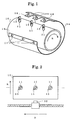
- Fig. 1 is a perspective view of an original fixing device of the first embodiment of the present invention.
- Fig. 2 is a plan view of a drum and a recording head.
- Fig. 3 is a broken view of a hook.
- Fig. 4 is a plan view of the bottom part of a lever.
- Fig. 5 is a cross sectional view of the hook attached to the drum.
- Figs. 6A through 6D are cross sectional views illustrating how the holder is attached to the drum.
- Fig. 7A through 7C are side views of the hook of the second embodiment of the present invention.
- Fig. 8 is a plan view of the bottom end of the lever of the second embodiment.
- FIG. 1 An original fixing device of an image reading scanner as the first embodiment of the present invention is described using Fig. 1 through Fig. 6D.
- a drum 10 and a reading head 32 are placed as shown in Fig. 2.
- the original fixing device of the present embodiment is composed of three hooks 11 planted in a row along a generatrix line of the drum 10 and a sheet holder 14.
- each of the hooks 11 is composed of: a lever 13, a ring 21 with a central bridge 22, a spring 23, a stem 12, and a pin 27.
- the lever 13 has a long recess at a side, thus forming a top claw and a bottom base.
- a stem base 25 is integrally formed at the bottom of the stem 12, and a slit 24 is formed in the upper part of the stem 12.
- the slit 24 has the width capable of admitting the lever 13.
- a through hole 26 is formed in the stem 12 in the direction perpendicular to the slit 24, and a through hole 28 is formed at the lower end of the lever 13 for admitting the pin 27 penetrating through the hole 26 of the stem 12.
- the hook 11 is constructed as follows. First the spring 23 is placed on the stem base 25 of the stem 12, and the ring 21 is placed on the spring 23 with the bridge 22 aligned with the slit 24 of the stem 12. The lever 13 also aligned with the slit 24 is moved downward pressing the ring 21. When the hole 28 is aligned with the hole 26 of the stem 12, the pin 27 is inserted through the holes 26 and 28 to engage the lever 13.
- the hook 11 thus constructed is inserted in a hole 29 formed on the drum 10 from the inside of the drum 10.
- the hook 11 stops when the stem base 25 abuts the inside surface of the drum 10 and the stem 12 rises above the surface of the drum 10.
- the sheet holder 14 is composed of two holding sheets and two end binders 15 and 16. Two holding sheets are made of transparent polyester film.
- the end binders 15 and 16 are made of rubber. As shown in Fig. 1, a row of holes 17 and 18 are formed in the end binders 15 and 16 corresponding to the hooks 11 on the drum 10, and the distance between the rows of holes 17 and 18 is made a little shorter than the peripheral length of the drum 10.
- the original fixing device of the present embodiment is used as follows. First an original is inserted between the two holding sheets of the sheet holder 14, where the reading face of the original is placed to the side of the transparent holding sheet. As shown in Fig. 6A, the sheet holder 14 is turned around the drum 11 with the reading surface of the original facing outside. The holes 17 of one end binder 15 are engaged with the stems 12 of the hooks 11 as shown in Fig. 6B. Then the levers 13 of the hooks 11 are leaned backward (that is, opposite to the top claw of the lever 13). As shown in Fig. 6C, the lever 13 rests at the leaned position owing to the corner cut 13b (Fig. 4) at the bottom of the lever 13. The holes 18 of the other end binder 16 are then engaged with the hooks 11. Finally, the levers 13 are turned forward (that is, to the direction of the top claw of the lever 13) until they lie as shown in Fig. 6D.
- end binders 15 and 16 are provided at both ends of the sheet holder 14, it is sufficient to provide one end binder at one end and holes can be formed directly in the sheet holder 14 at the other end. Further it is possible to do without the sheet holder and attach the end binders 15 and 16 having the holes 17 and 18 directly to the original (or the photosensitive film in case of an image recording scanner). If the original (or the photosensitive film) is elastic by itself, the holes can be formed in the original itself corresponding to the hooks 11.
- Fig. 8 The mechanism of stabilizing the lying lever 40 is detailed in Fig. 8.
- the geometry is as follows.
- Point G is the foot of the perpendicular line falling from the center I of the pin 42 when the lever 40 is at the position of Fig. 7B
- point F is the foot of the perpendicular line falling from the center I when the lever 40 is at the position of Fig. 7C
- Point E is the topward end of the side 40c
- point H is the bottomward end of the side 40c.
Landscapes
- Engineering & Computer Science (AREA)
- Multimedia (AREA)
- Signal Processing (AREA)
- Facsimile Scanning Arrangements (AREA)
Claims (6)
- Blattbefestigungsvorrichtung zum Befestigen eines Blattes auf einer Trommel (10) eines Abtasters vom Trommeltyp, wobei das Blatt eine Länge hat, die dem Umfang der Trommel (10) entspricht, wobei die Blattbefestigungsvorrichtung aufweist:a) eine Vielzahl von Stäben (12, 45), die auf der Oberfläche der Trommel (10) steht;b) einen Hebel (13, 40), der drehbar an jedem der Vielzahl der Stäbe (12, 45) befestigt ist, wobei der Hebel (13, 40) zwischen einer aufrechten Position und einer liegenden Position drehbar ist; undc) einen Stabilisierer, der bei jedem der Vielzahl der Stäbe (12, 45) und bei jedem der Hebel (13, 40) vorgesehen ist, um den Hebel (13, 40) in der liegenden Position zu stabilisieren.
- Blattbefestigungsvorrichtung nach Anspruch 1, bei der die Blattbefestigungsvorrichtung weiterhin einen Blatthalter (14) zum Halten des Blattes aufweist, der eine Reihe Löcher (17, 18) an jedem der gegenüberliegenden Enden des Blatthalters (14) hat.
- Blattbefestigungsvorrichtung nach Anspruch 2, bei der der Hebel (13, 40) mit einem Stift (27, 42) an jedem der Vielzahl der Stäbe (12, 45) befestigt ist, wobei der Hebel (13, 40) eine Ebene (13c) hat, die im wesentlichen parallel zu der Verlängerung der Stäbe (12, 45) ist, wenn der Hebel (13, 40) in der aufrechten Position ist, und die im wesentlichen senkrecht zu der Verlängerung der Stäbe (12, 45) ist, wenn der Hebel (13, 40) in der liegenden Position ist, und der Stabilisierer eine Platte (21, 22; 43) unter dem Hebel und eine Feder (23; 44) zum Zwingen der Platte in die Ebene (13c) hat, wenn der Hebel (13, 40) in der liegenden Position ist.
- Blattbefestigungsvorrichtung nach Anspruch 3, bei der der Hebel (13, 40) ein L-förmiges Loch (41) zum Aufnehmen des Stiftes (42) hat, wobei eine Arm des L-förmigen Loches (41) zu der Ebene (13c) gerichtet ist, wodurch der Stift in den Arm fällt, wenn der Hebel (13, 40) in der liegenden Position ist und in eine Richtung im wesentlichen senkrecht zu der Verlängerung der Stäbe (12, 45) verlagert worden ist.
- Blattbefestigungsvorrichtung nach Anspruch 3 oder 4, bei der eine Drehrichtung des Hebels (13, 40) schräg zu einer Drehrichtung der Trommel (10) ist.
- Blattbefestigungsvorrichtung nach Anspruch 3 oder 4, bei der der Hebel (40) einen Eckenausschnitt hat, der sich von der Ebene (13c) zu einer unteren Ebene (13a) des Hebels (40) erstreckt, wobei der Ausschnitt zu einer zusätzlichen Ebene führt, in die die Platte (43) durch die Feder (44) gezwungen wird, so daß eine stabile Zwischenposition des Hebels (40) zwischen der aufrechten Position und der liegenden Position realisiert wird.
Applications Claiming Priority (2)
| Application Number | Priority Date | Filing Date | Title |
|---|---|---|---|
| JP53381/93U | 1993-09-06 | ||
| JP053381U JPH0720757U (ja) | 1993-09-06 | 1993-09-06 | ドラム型走査装置用シート保持装置 |
Publications (2)
| Publication Number | Publication Date |
|---|---|
| EP0642254A1 EP0642254A1 (de) | 1995-03-08 |
| EP0642254B1 true EP0642254B1 (de) | 1998-11-25 |
Family
ID=12941250
Family Applications (1)
| Application Number | Title | Priority Date | Filing Date |
|---|---|---|---|
| EP94113903A Expired - Lifetime EP0642254B1 (de) | 1993-09-06 | 1994-09-05 | Blattaufspannungsgerät für Trommel eines Abtasters |
Country Status (4)
| Country | Link |
|---|---|
| US (1) | US5473407A (de) |
| EP (1) | EP0642254B1 (de) |
| JP (1) | JPH0720757U (de) |
| DE (1) | DE69414788T2 (de) |
Families Citing this family (8)
| Publication number | Priority date | Publication date | Assignee | Title |
|---|---|---|---|---|
| DE4447179A1 (de) * | 1994-12-30 | 1996-07-04 | Koenig & Bauer Albert Ag | Gummituchzylinder für Offsetdruck |
| US5731866A (en) * | 1995-08-29 | 1998-03-24 | Eskofot A/S | Apparatus and a method for irradiating a section of a length of a sheet-like material |
| US5937760A (en) * | 1996-03-19 | 1999-08-17 | Mitsubishi Paper Mills, Limited | Method and device for mounting a lithoplate using register pins |
| US5953807A (en) * | 1997-12-30 | 1999-09-21 | Agfa Corporation | Method for installing and aligning punches in an imaging system |
| JP4612899B2 (ja) * | 2006-02-17 | 2011-01-12 | キヤノン株式会社 | シート搬送ローラ、シート搬送装置、及び画像形成装置 |
| US11370217B2 (en) * | 2018-11-18 | 2022-06-28 | Landa Corporation Ltd. | Improving printed output of digital printing systems by reduction of unprinted margins of the substrate |
| GB2582334B (en) | 2019-03-19 | 2022-02-23 | Landa Labs 2012 Ltd | Condensation curable coating composition comprising polydimethylsiloxane-silanol and silicone resin-silanol and use thereof |
| GB2582333B (en) | 2019-03-19 | 2021-08-18 | Landa Labs 2012 Ltd | Arrangements for securing cylinder jackets |
Family Cites Families (12)
| Publication number | Priority date | Publication date | Assignee | Title |
|---|---|---|---|---|
| GB704152A (en) * | 1950-11-01 | 1954-02-17 | Postmaster General | Improvements in or relating to facsimile telegraph apparatus |
| US2878095A (en) * | 1953-01-07 | 1959-03-17 | Western Union Telegraph Co | Facsimile scanning drum sheet holder apparatus |
| GB745218A (en) * | 1953-03-05 | 1956-02-22 | Muirhead & Co Ltd | Improvements in or relating to machines for facsimile transmission and reproduction, photo-telegraphy, or copying telegraphy |
| US3610121A (en) * | 1969-03-05 | 1971-10-05 | Compugraphic Corp | Photocomposing machine |
| US3710707A (en) * | 1971-09-28 | 1973-01-16 | Compugraphic Corp | Font strip structure |
| US3896728A (en) * | 1973-03-22 | 1975-07-29 | Asahi Chemical Ind | Printing sheet gripping device for use with printing saddle |
| JPS5918778A (ja) * | 1982-07-22 | 1984-01-31 | Teijin Ltd | ポリエステルバインダ−繊維 |
| DE3611850A1 (de) * | 1985-04-10 | 1986-10-16 | Sharp K.K., Osaka | Automatischer vorlageneinzug |
| DE4205276A1 (de) * | 1992-02-21 | 1993-08-26 | Roland Man Druckmasch | Vorrichtung zum aufspannen einer druckplatte auf einen plattenzylinder |
| AU665823B2 (en) * | 1992-04-13 | 1996-01-18 | Toyo Ink Manufacturing Co. Ltd. | Image transfer apparatus |
| DE4214168C2 (de) * | 1992-04-30 | 1994-10-06 | Roland Man Druckmasch | Vorrichtung zum Aufspannen von Druckplatten auf dem Plattenzylinder von Druckmaschinen, insbesondere Bogenoffsetdruckmaschinen |
| US5383001A (en) * | 1993-02-22 | 1995-01-17 | Intergraph Corporation | Vacuum drum for mounting media of different sizes |
-
1993
- 1993-09-06 JP JP053381U patent/JPH0720757U/ja active Pending
-
1994
- 1994-09-02 US US08/300,459 patent/US5473407A/en not_active Expired - Fee Related
- 1994-09-05 DE DE69414788T patent/DE69414788T2/de not_active Expired - Fee Related
- 1994-09-05 EP EP94113903A patent/EP0642254B1/de not_active Expired - Lifetime
Also Published As
| Publication number | Publication date |
|---|---|
| US5473407A (en) | 1995-12-05 |
| DE69414788D1 (de) | 1999-01-07 |
| EP0642254A1 (de) | 1995-03-08 |
| DE69414788T2 (de) | 1999-04-15 |
| JPH0720757U (ja) | 1995-04-11 |
Similar Documents
| Publication | Publication Date | Title |
|---|---|---|
| US5109980A (en) | Ic carrier with shaft coupling | |
| US5473407A (en) | Sheet fixing device for a drum of a scanner | |
| US5387120A (en) | Latching IC connector | |
| JPH0539594Y2 (de) | ||
| JP4172856B2 (ja) | Icソケット | |
| US5683262A (en) | IC socket | |
| US4749098A (en) | File card container | |
| EP0168106A1 (de) | Plattenspieler mit Hebevorrichtung für den Tonabnehmer | |
| JPS6239593Y2 (de) | ||
| JPH0647736Y2 (ja) | 用紙位置決め機構の取付構造 | |
| KR940008126Y1 (ko) | 턴테이블의 디스크 지지장치 | |
| JP3533829B2 (ja) | 光ディスク装置 | |
| JPH0142845Y2 (de) | ||
| JPH0723960Y2 (ja) | Icキャリア | |
| JP2747134B2 (ja) | コンタクタ | |
| JPH0433584Y2 (de) | ||
| JP2584968B2 (ja) | カセツト装着装置 | |
| JPH0731397Y2 (ja) | テープカセット装填装置 | |
| JPS6347443U (de) | ||
| JPS5889494U (ja) | 係留鎖一斉離脱装置 | |
| US4606098A (en) | Pendulum rod immobilizing device | |
| JPS5813490Y2 (ja) | カセット装着装置 | |
| JPS6035340Y2 (ja) | 交換可能のトレ−ス針を有するピツクアツプ | |
| JPS6016987Y2 (ja) | 熟語ブツク保持機構 | |
| JP2679264B2 (ja) | ディスクドライブ装置 |
Legal Events
| Date | Code | Title | Description |
|---|---|---|---|
| PUAI | Public reference made under article 153(3) epc to a published international application that has entered the european phase |
Free format text: ORIGINAL CODE: 0009012 |
|
| AK | Designated contracting states |
Kind code of ref document: A1 Designated state(s): DE FR GB |
|
| 17P | Request for examination filed |
Effective date: 19950809 |
|
| 17Q | First examination report despatched |
Effective date: 19970626 |
|
| GRAG | Despatch of communication of intention to grant |
Free format text: ORIGINAL CODE: EPIDOS AGRA |
|
| GRAG | Despatch of communication of intention to grant |
Free format text: ORIGINAL CODE: EPIDOS AGRA |
|
| GRAH | Despatch of communication of intention to grant a patent |
Free format text: ORIGINAL CODE: EPIDOS IGRA |
|
| GRAH | Despatch of communication of intention to grant a patent |
Free format text: ORIGINAL CODE: EPIDOS IGRA |
|
| GRAA | (expected) grant |
Free format text: ORIGINAL CODE: 0009210 |
|
| AK | Designated contracting states |
Kind code of ref document: B1 Designated state(s): DE FR GB |
|
| PG25 | Lapsed in a contracting state [announced via postgrant information from national office to epo] |
Ref country code: FR Free format text: LAPSE BECAUSE OF FAILURE TO SUBMIT A TRANSLATION OF THE DESCRIPTION OR TO PAY THE FEE WITHIN THE PRESCRIBED TIME-LIMIT Effective date: 19981125 |
|
| REF | Corresponds to: |
Ref document number: 69414788 Country of ref document: DE Date of ref document: 19990107 |
|
| EN | Fr: translation not filed | ||
| PLBE | No opposition filed within time limit |
Free format text: ORIGINAL CODE: 0009261 |
|
| STAA | Information on the status of an ep patent application or granted ep patent |
Free format text: STATUS: NO OPPOSITION FILED WITHIN TIME LIMIT |
|
| 26N | No opposition filed | ||
| REG | Reference to a national code |
Ref country code: GB Ref legal event code: IF02 |
|
| PGFP | Annual fee paid to national office [announced via postgrant information from national office to epo] |
Ref country code: GB Payment date: 20050831 Year of fee payment: 12 |
|
| PGFP | Annual fee paid to national office [announced via postgrant information from national office to epo] |
Ref country code: DE Payment date: 20050902 Year of fee payment: 12 |
|
| PG25 | Lapsed in a contracting state [announced via postgrant information from national office to epo] |
Ref country code: DE Free format text: LAPSE BECAUSE OF NON-PAYMENT OF DUE FEES Effective date: 20070403 |
|
| GBPC | Gb: european patent ceased through non-payment of renewal fee |
Effective date: 20060905 |
|
| PG25 | Lapsed in a contracting state [announced via postgrant information from national office to epo] |
Ref country code: GB Free format text: LAPSE BECAUSE OF NON-PAYMENT OF DUE FEES Effective date: 20060905 |