EP0642636B1 - Getriebeanordnung - Google Patents
Getriebeanordnung Download PDFInfo
- Publication number
- EP0642636B1 EP0642636B1 EP93913842A EP93913842A EP0642636B1 EP 0642636 B1 EP0642636 B1 EP 0642636B1 EP 93913842 A EP93913842 A EP 93913842A EP 93913842 A EP93913842 A EP 93913842A EP 0642636 B1 EP0642636 B1 EP 0642636B1
- Authority
- EP
- European Patent Office
- Prior art keywords
- gear
- pinion
- shaft
- face
- gears
- Prior art date
- Legal status (The legal status is an assumption and is not a legal conclusion. Google has not performed a legal analysis and makes no representation as to the accuracy of the status listed.)
- Expired - Lifetime
Links
- 230000000452 restraining effect Effects 0.000 claims 1
- 230000008878 coupling Effects 0.000 description 8
- 238000010168 coupling process Methods 0.000 description 8
- 238000005859 coupling reaction Methods 0.000 description 8
- 230000005540 biological transmission Effects 0.000 description 7
- 238000000605 extraction Methods 0.000 description 5
- 230000033001 locomotion Effects 0.000 description 3
- 230000009467 reduction Effects 0.000 description 3
- 230000009471 action Effects 0.000 description 2
- 230000003247 decreasing effect Effects 0.000 description 1
- 230000009977 dual effect Effects 0.000 description 1
- 230000000694 effects Effects 0.000 description 1
- 239000000446 fuel Substances 0.000 description 1
- 238000004519 manufacturing process Methods 0.000 description 1
- 230000007246 mechanism Effects 0.000 description 1
- 230000004048 modification Effects 0.000 description 1
- 238000012986 modification Methods 0.000 description 1
- 230000036316 preload Effects 0.000 description 1
Images


Classifications
-
- F—MECHANICAL ENGINEERING; LIGHTING; HEATING; WEAPONS; BLASTING
- F16—ENGINEERING ELEMENTS AND UNITS; GENERAL MEASURES FOR PRODUCING AND MAINTAINING EFFECTIVE FUNCTIONING OF MACHINES OR INSTALLATIONS; THERMAL INSULATION IN GENERAL
- F16H—GEARING
- F16H1/00—Toothed gearings for conveying rotary motion
- F16H1/02—Toothed gearings for conveying rotary motion without gears having orbital motion
- F16H1/04—Toothed gearings for conveying rotary motion without gears having orbital motion involving only two intermeshing members
- F16H1/12—Toothed gearings for conveying rotary motion without gears having orbital motion involving only two intermeshing members with non-parallel axes
-
- F—MECHANICAL ENGINEERING; LIGHTING; HEATING; WEAPONS; BLASTING
- F16—ENGINEERING ELEMENTS AND UNITS; GENERAL MEASURES FOR PRODUCING AND MAINTAINING EFFECTIVE FUNCTIONING OF MACHINES OR INSTALLATIONS; THERMAL INSULATION IN GENERAL
- F16H—GEARING
- F16H55/00—Elements with teeth or friction surfaces for conveying motion; Worms, pulleys or sheaves for gearing mechanisms
- F16H55/02—Toothed members; Worms
- F16H55/17—Toothed wheels
- F16H2055/173—Crown gears, i.e. gears have axially arranged teeth
-
- Y—GENERAL TAGGING OF NEW TECHNOLOGICAL DEVELOPMENTS; GENERAL TAGGING OF CROSS-SECTIONAL TECHNOLOGIES SPANNING OVER SEVERAL SECTIONS OF THE IPC; TECHNICAL SUBJECTS COVERED BY FORMER USPC CROSS-REFERENCE ART COLLECTIONS [XRACs] AND DIGESTS
- Y10—TECHNICAL SUBJECTS COVERED BY FORMER USPC
- Y10T—TECHNICAL SUBJECTS COVERED BY FORMER US CLASSIFICATION
- Y10T74/00—Machine element or mechanism
- Y10T74/19—Gearing
- Y10T74/19023—Plural power paths to and/or from gearing
- Y10T74/19074—Single drive plural driven
-
- Y—GENERAL TAGGING OF NEW TECHNOLOGICAL DEVELOPMENTS; GENERAL TAGGING OF CROSS-SECTIONAL TECHNOLOGIES SPANNING OVER SEVERAL SECTIONS OF THE IPC; TECHNICAL SUBJECTS COVERED BY FORMER USPC CROSS-REFERENCE ART COLLECTIONS [XRACs] AND DIGESTS
- Y10—TECHNICAL SUBJECTS COVERED BY FORMER USPC
- Y10T—TECHNICAL SUBJECTS COVERED BY FORMER US CLASSIFICATION
- Y10T74/00—Machine element or mechanism
- Y10T74/19—Gearing
- Y10T74/19633—Yieldability in gear trains
-
- Y—GENERAL TAGGING OF NEW TECHNOLOGICAL DEVELOPMENTS; GENERAL TAGGING OF CROSS-SECTIONAL TECHNOLOGIES SPANNING OVER SEVERAL SECTIONS OF THE IPC; TECHNICAL SUBJECTS COVERED BY FORMER USPC CROSS-REFERENCE ART COLLECTIONS [XRACs] AND DIGESTS
- Y10—TECHNICAL SUBJECTS COVERED BY FORMER USPC
- Y10T—TECHNICAL SUBJECTS COVERED BY FORMER US CLASSIFICATION
- Y10T74/00—Machine element or mechanism
- Y10T74/19—Gearing
- Y10T74/19642—Directly cooperating gears
- Y10T74/1966—Intersecting axes
Definitions
- the present invention relates to gear arrangements.
- a variety of gear arrangements are known for transmitting torque through an angle and, in particular, concern the transmission of power from an engine shaft to a driven shaft that is situated at a 90° angle to the engine shaft.
- US Patent No 2,865,219 issued to Alfred W Allen discloses a power transmission system by which power to turn a shaft is applied equally to the driven member at a plurality of circumferential points equally displaced in a diametrical plane of such driven member.
- the gear arrangement includes a driving bevel gear mounted to a driving shaft.
- the driving bevel gear is in meshing engagement with both a driven bevel gear mounted to a driven shaft and a "cross-over" bevel gear that transmits power to a fourth gear on the side opposite of the driving bevel gear.
- the fourth gear meshes with both the driven and cross-over gears.
- the patent proposes to divide the power by applying equal parts of the power to the driven gear at opposite points.
- the patent does not describe a mechanism to ensure that equal load division will occur, eg, manufacturing tolerance differences could result in all power going through one path and none through the other. In other words, the torque split is indeterminate.
- the patent further describes a through shaft that requires an additional set of bearings and structural elements because the through shaft turns in an opposing direction to the gear through which the shaft passes.
- the gear arrangement described also does not utilize any power extraction between the cross-over gear and the driven gear.
- US Patent No 4,437,355 issued to Andre Bordat also describes a bevel gear power transmitting arrangement having a first bevel gear coupled to a driving shaft, a second bevel gear coupled to a driven shaft whose axis is perpendicular to that of the driving shaft and meshing with the first bevel gear, a third loose bevel gear coaxial with the second one and meshing with the first one, and a fourth loose bevel gear coaxial with the first one and meshing with the second and third ones.
- the patent proposes mounting the driving gear so that it remains slightly floating.
- the gear arrangement described incorporates a swivel pin, bearing and thrust bearings to prevent axial movement of the driving gear.
- the patent further describes a through shaft that requires an additional set of bearings and structural elements.
- the gear arrangement described also fails to utilize any power extraction between the second and third bevel gears.
- PCT Patent Publication WO 92/06317 discloses a gear arrangement having two concentric counter-rotating face gears in meshing engagement with an engine output shaft.
- the face gears are connected to respective concentric, vertical counter rotating face gear shafts of unequal length, each shaft ending in a helical spur gear that is in meshing engagement with an output helical face gear.
- the helical output face gear is connected to the output shaft, thereby completing an offset transmission.
- the face gear shafts can be coupled together by means of thrust bearings that couple the axial thrusts of one shaft to the other in an opposite direction.
- the shafts can also be coupled via a preload spring that ensures that the torque split between the pinion gears is statically determinant.
- the gear arrangement can be applied to twin engine designs, with a spur gear train coupling the two engines together via an interconnect shaft.
- the gear arrangement thus discloses a pinion shaft for receiving torque from the output shaft, a pinion mounted concentrically to a first end of the pinion shaft, upper and lower concentric and opposed face gears meshingly engaged with said pinion, means for permitting the pinion to float such that torque from the pinion shaft is split equally between the face gears and a primary driven shaft coupled to one of said face gears.
- a single driving shaft be used to power a number of auxiliary devices.
- the engine is used to drive the helicopter rotor shaft as well as other devices such as the tail rotor, generators, hydraulic pumps, fuel pumps, oil pumps, etc.
- a gear arrangement for transmitting torque from an output shaft of an engine comprising a pinion shaft for receiving torque from the output shaft, a pinion mounted concentrically to a first end of the pinion shaft, upper and lower concentric and opposed face gears meshingly engaged with said pinion, means for permitting the pinion to float such that torque from the pinion shaft is split equally between the face gears and a primary driven shaft coupled to one of said face gears characterized by at least one non-floating shaft having a gear in meshing engagement with said first and second face gears.
- a feature of the embodiments to be described is the use of a drive shaft support that permits the spur gear pinion to float freely between the face gears so as to divide the input torque between the two face gears.
- the driving shaft is located by a bearing or a flexible coupling at the shaft end remote from the gear box to allow the pinion to float freely.
- This floating freedom does no harm because the two opposing face gears engaged by the pinion are tolerant of axial or radial motion. Because the motion is very weakly restrained, the floating spur gear pinion is forced to move to a balanced position and the torque will be divided precisely between the two driven face gears by the opposed meshing forces.
- the torque supplied to a first of the face gears goes directly to output.
- the torque supplied to the other face gear is transferred by the non-floating spur gear to the first face gear and then to output.
- this arrangement can double the power transmitted by a given size face gear or allow a reduction in face gear size for a given power.
- Another feature of the embodiments to be described is that useful power may be extracted from both face gears and the non-floating spur gear as well as additional spur gears that are placed in meshing engagement with the face gears.
- the additional gears may be used to operate a generator, various pumps or other devices. This power extraction has no effect on the accuracy of the torque split.
- the arrangement allows the designer to provide the desired hand of rotation to the primary output shaft, either clockwise or counterclockwise, by choosing which face gear will be the preferred output.
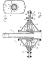
- a transmission constructed in accordance with the present invention as shown in FIG. 1, has a pinion shaft 20 extending from an engine (which is not shown) and a spur gear type pinion 22 at one end of the shaft.
- the spur gear type pinion has radial teeth 24 on its rim, with edges parallel to the axis of rotation.
- the opposite end of the shaft is connected to the output shaft 26 of the engine and is supported by a flexible coupling 28.
- the pinion 22 As the pinion 22 rotates, it drives an upper face gear 32 and a lower face gear 34.
- the face gears are mounted concentrically and are in opposed relationship to each other.
- the spur gear pinion is located between the face gears and meshes with the lower surface 36 of the upper face gear and the upper surface 38 of the lower face gear.
- This exemplary pinion is provided with 28 teeth.
- the engaging surfaces of both face gears have 127 teeth 40 whose edges are radially directed along the gear periphery, toward the center of the gear, and have a pitch so as to be in smooth meshing engagement with the pinion teeth 24.
- the exemplary ratio of 127/28 for the face gear teeth to the pinion teeth provides a drive transfer ratio, or speed reduction, of greater than 4-to-1.
- the upper face gear 32 rotates about an upper face gear shaft 42 which is rotatably supported and positioned by a lower bearing 80 and an upper bearing 82.
- the lower face gear 34 rotates about a lower face gear shaft 46 which is rotatably supported and positioned by a lower bearing 84 and an upper bearing 86.
- the shafts rotate about concentric axes. As seen in FIG. 1, for a given hand of rotation of the pinion shaft 20, the face gears and their respective shafts rotate in opposite directions. It should be apparent that the face gears rotate about an axis that is at an angle of approximately 90° from the axis of rotation of the pinion shaft. That is, a pinion gear and paired face gear combination is used to turn the corner, in the manner described in U.S. Patent No. 5,135,442 by the present inventor, which is incorporated herein by reference.
- the flexible coupling 28 permits the pinion shaft and the pinion to float, both axially and radially, so as to provide automatic and flexible balancing between the two torques transferred respectively from the pinion to the two face gears with which it is engaged.
- the flexible coupling may be substituted by a duplex pair of ball bearings 50 (e.g. angular contact bearings) mounted face-to-face to provide a pivot point 52 (see FIG. 2).
- the lines of action of the two bearings face toward each other so that they coincide at the axis of rotation of the pinion shaft to provide a pivot point.
- a crowned splined coupling or universal joint may be used.
- a flexible coupling, a ball bearing arrangement, a crowned splined coupling or other similar means the position of the pinion gear is permitted to automatically adjust between the face gears so that the two torques transferred to the face gears are substantially identical.
- the pinion and face gears provide a spur/face gear arrangement that exhibits true conjugate action and accommodates high speed-reduction ratios. Such an arrangement is also tolerant of thermal changes and deflections under load, and increases the quietness and smoothness of operation.
- a non-floating spur gear 60 is mounted between the face gears at a location 180° around the periphery of the face gears from the floating pinion 22.
- the non-floating spur gear is mounted at one end of a shaft 62.
- the other end of the shaft may be operably connected to an auxiliary device 90 (see FIG. 4) to receive power from the shaft.
- the non-floating spur gear and its shaft are rotatably supported and positioned by a pair of bearings 64.
- the non-floating spur gear performs a dual function by first serving as a crossover gear, transferring power from one face gear to the other face gear and, second, by serving as a power extraction path for providing power to auxiliary devices such as generators and pumps.
- a plurality of such non-floating spur gears 92 and shafts 94 may be added along the periphery of the face gears to provide power to other auxiliary devices 96 as desired or to provide a plurality of load paths transferring power from one face gear to the other (see FIG. 4).
- the gear arrangement shown in FIG. 1 can double the power transmitted by a given size face gear or allow a reduction in the size of the face gear for a given power. Because the pinion is permitted to float freely, the pinion torque will be divided precisely between the two face gears by the opposing meshing forces.
- the torque supplied to the upper face gear goes directly to the rotor shaft.
- the torque supplied to the lower face gear is transferred by the non-floating spur gear to the upper face gear and to the rotor shaft.
- the floating pinion allows power to be absorbed by any or all of the other three shafts, i.e., the non-floating spur gear, the upper face gear or the lower face gear. This capability does not affect the torque split. Useful power may also be extracted from the lower face gear to operate another auxiliary device 98.
- FIG. 2 a second preferred embodiment of the invention is shown wherein a helicopter rotor shaft 70 is mounted to the lower face gear thus reversing the hand of rotation of the rotor shaft from that shown in FIG. 1.
- Each face gear has a cone portion 110 welded to a disk portion 112 for optimum strength.
- the upper face gear 32 is straddle mounted and located by an upper bearing 114 and a lower bearing 116.
- the lower face gear 34 is straddle mounted and located by an upper bearing 118 and a lower bearing 120.
- the bearings 116 and 118 interposed between the face gears are mounted to a flat plate 74 having a cylindrical mount portion 78 and serve to locate cylindrical extension portions 122 extending outwardly from the disk portions of the face gears (see also FIG. 3).
- the flat plate is secured to the helicopter structure by bolts 124 and may include recesses (not shown) for locating additional non-floating spur gears between the face gears.
- the rotor shaft may be mounted to the lower face gear by a spline 76 at the top end of the bottom face gear.
- An added safety feature is a non-contacting roller bearing set 130 that provides a restraint for the pinion 22 in the event of a failure of one of the face gears.
- the roller bearing set is separated from its outer contact surface 132 a sufficient distance to permit normal floating of the pinion.
- helical gears can be used instead of spur gears.
Landscapes
- Engineering & Computer Science (AREA)
- General Engineering & Computer Science (AREA)
- Mechanical Engineering (AREA)
- Gear Transmission (AREA)
Claims (9)
- Getriebeanordnung zum Übertragen eines Drehmomentes von einer Abtriebswelle (26) eines Motors umfassend eine Zahnradwelle (20) zum Aufnehmen des Drehmomentes von der Abtriebswelle (26), ein konzentrisch auf ein erstes Ende der Zahnradwelle (20) angeordnetes Zahnrad (22), mit oberen und unteren konzentrisch und gegenüberliegend angeordneten Zahnkreisen (32, 34), die mit dem Zahnrad (22) verzahnt ineinander greifen, eine Einrichtung (28), die erlaubt, daß das Zahnrad derart verlagerbar ist, daß das Drehmoment von der Zahnradwelle (22) gleichmäßig zwischen den Zahnkreisen (32, 34) und einer Primärantriebswelle (42, 46) verteilt wird, die an einen der Zahnkreise (32, 34) gekoppelt ist,
dadurch gekennzeichnet,
daß wenigstens eine nicht-verlagerbare Welle (62) mit einem Zahnrad (60) in verzahnter Ineingriffnahme mit dem ersten und zweiten Zahnkreis (32, 34) steht. - Anordnung nach Anspruch 1,
dadurch gekennzeichnet,
daß eine Hilfseinrichtung mit der nicht-verlagerbaren Welle (62) verbunden ist, und von dieser angetrieben wird. - Anordnung nach Anspruch 2,
dadurch gekennzeichnet,
daß mehrere nicht-verlagerbare Wellen (62) jeweils mit mehreren Hilfseinrichtungen jeweils verbunden sind und diese antreiben. - Anordnung nach Anspruch 1,
dadurch gekennzeichnet,
daß eine Sekundärantriebswelle (46) mit dem anderen Zahnkreis (34) gekoppelt ist und sich entgegengesetzt zu der Primärantriebswelle (42) dreht. - Anordnung nach Anspruch 4,
dadurch gekennzeichnet,
daß die Sekundärantriebswelle (46) mit einer Hilfseinrichtung verbunden ist und diese antreibt. - Anordnung nach einem der Ansprüche 1 bis 5,
dadurch gekennzeichnet,
daß die Primärantriebswelle (70) am unteren Zahnkreis (34) befestigt ist und sich nach oben durch den oberen Zahnkreis (32) erstreckt. - Anordnung nach einem der Ansprüch 1 bis 6,
gekennzeichnet durch,
eine Einrichtung (130) zum Halten des Zahnrades (22) bei einem Ausfall eines der Zahnkreise (32, 34). - Anordnung nach einem der Ansprüche 1 bis 7,
gekennzeichnet durch
Lager (116, 118) und eine Platte (74), die zwischen den Zahnkreisen (32, 34) angeordnet ist, wobei die Lager (116, 118) an einem zylindrischen Befestigungsteil (78) der Platte (74) befestigt sind, um ein unteres Ende des oberen Zahnkreises (32) und ein oberes Ende des unteren Zahnkreises (34) anzuordnen. - Anordnung nach einem der vorhergehenden Ansprüche,
dadurch gekennzeichnet,
daß die Einrichtung (28), die ein Verlagern des Zahnrades erlaubt, Mittel umfaßt, die dem Zahnrad ein radiales und axiales Verlagern derart erlauben, daß das Drehmoment von der Zahnradwelle (20) gleichmäßig zwischen den Zahnkreisen (32, 34) aufgeteilt wird.
Applications Claiming Priority (3)
| Application Number | Priority Date | Filing Date | Title |
|---|---|---|---|
| US07/888,190 US5233886A (en) | 1992-05-26 | 1992-05-26 | Increased capacity face gear arrangement for transmitting torque through an angle and to a plurality of power extraction paths |
| PCT/US1993/004490 WO1993024766A1 (en) | 1992-05-26 | 1993-04-30 | Increased capacity face gear arrangement for transmitting torque through an angle to a plurality of power paths |
| US888190 | 2004-07-09 |
Publications (3)
| Publication Number | Publication Date |
|---|---|
| EP0642636A1 EP0642636A1 (de) | 1995-03-15 |
| EP0642636A4 EP0642636A4 (de) | 1995-07-19 |
| EP0642636B1 true EP0642636B1 (de) | 1999-08-04 |
Family
ID=25392702
Family Applications (1)
| Application Number | Title | Priority Date | Filing Date |
|---|---|---|---|
| EP93913842A Expired - Lifetime EP0642636B1 (de) | 1992-05-26 | 1993-04-30 | Getriebeanordnung |
Country Status (7)
| Country | Link |
|---|---|
| US (1) | US5233886A (de) |
| EP (1) | EP0642636B1 (de) |
| JP (1) | JP3075483B2 (de) |
| AU (1) | AU4372893A (de) |
| CA (1) | CA2136642C (de) |
| DE (1) | DE69325907T2 (de) |
| WO (1) | WO1993024766A1 (de) |
Families Citing this family (45)
| Publication number | Priority date | Publication date | Assignee | Title |
|---|---|---|---|---|
| IT1261872B (it) * | 1993-09-17 | 1996-06-03 | Fiatavio Spa | Applicazione di ingranaggi facciali a trasmissioni per elicotteri. |
| JPH09510767A (ja) * | 1993-12-06 | 1997-10-28 | ヴォアク ヒドラウリークス アクチボラゲット | 歯車装置 |
| US5501636A (en) * | 1994-01-10 | 1996-03-26 | Woods Equipment Corporation | Rotary machine system having hollow tube shaft and plural output shafts |
| US5525970A (en) * | 1994-04-12 | 1996-06-11 | The United States Of America As Represented By The Secretary Of The Army | Safety system and technique for multi-aperture optical systems |
| NL194681C (nl) * | 1994-11-22 | 2002-11-04 | Ihc Holland Nv | Tandwielkast voor continu variabele overbrenging. |
| US5509862A (en) * | 1994-12-19 | 1996-04-23 | General Motors Corporation | Right angle differential drive gear assembly |
| US6183388B1 (en) * | 1996-03-12 | 2001-02-06 | Allison Engine Company, Inc. | Epicyclic face gear reduction gearbox particularly for a gas turbine engine |
| US6146253A (en) * | 1996-04-23 | 2000-11-14 | Mcdonnell Douglas Helicopter Company | Apparatus and method for precision grinding face gear |
| US5823857A (en) * | 1996-04-23 | 1998-10-20 | Mcdonnell Douglas Helicopter Company | Apparatus and method for precision grinding of face gears |
| US5823470A (en) * | 1996-07-16 | 1998-10-20 | Mcdonnell Douglas Helicopter Co. | Split torque proprotor transmission |
| US5862706A (en) * | 1996-07-16 | 1999-01-26 | Mcdonnell Douglas Helicopter Company | Shaft deflection controller |
| US5802918A (en) * | 1996-10-16 | 1998-09-08 | Mcdonnell Douglas Helicopter Co. | Concentric face gear transmission assembly |
| US6129793A (en) * | 1997-08-11 | 2000-10-10 | Tan; Jie | Face-gear forging method |
| IT1297939B1 (it) * | 1997-12-23 | 1999-12-20 | Fiatavio Spa | Gruppo di trasmissione ad ingranaggi |
| CA2240752C (en) * | 1998-06-16 | 2006-07-25 | Fiatavio S.P.A. | Face-gear transmission assembly with floating balance pinions |
| DE69809404T2 (de) * | 1998-06-18 | 2003-07-10 | Fiatavio S.P.A., Turin/Torino | Kronradgetriebeanordnung mit beweglich angeordneten Ritzeln |
| US6302356B1 (en) | 1998-08-21 | 2001-10-16 | Rolls-Royce Corporation | Helicopter two stage main reduction gearbox |
| IT1303139B1 (it) * | 1998-10-16 | 2000-10-30 | Fiatavio Spa | Gruppo di trasmissione ad ingranaggi facciali, particolarmente perapplicazioni aeronautiche. |
| DE10019686A1 (de) * | 2000-04-20 | 2001-10-31 | Nem Power Systems Niederlassun | Klappe, insbesondere Umschaltklappe für große Kanalquerschnitte |
| NL1016550C2 (nl) * | 2000-11-06 | 2002-05-22 | Crown Gear Holding B V | Tandwieloverbrenging. |
| DE10065108C2 (de) * | 2000-12-28 | 2003-06-18 | Gkn Automotive Gmbh | Winkelgetriebe mit Ringgehäuse |
| DE10065107C2 (de) * | 2000-12-28 | 2003-06-05 | Gkn Automotive Gmbh | Winkelgetriebe mit Leistungsverzweigung |
| US6443035B1 (en) | 2001-09-20 | 2002-09-03 | The Boeing Company | Hybrid power input quill for transmissions |
| FR2830307B1 (fr) * | 2001-10-02 | 2003-12-05 | Eurocopter France | Boite de transmission de puissance basculante a roues a denture frontale peripherique de type "far gear" |
| US6612195B2 (en) | 2001-11-26 | 2003-09-02 | Sikorsky Aircraft Corporation | Split-torque face gear transmission |
| US20040214682A1 (en) * | 2003-04-28 | 2004-10-28 | Sbabo Thomas L. | Dual stage differential speed transmission |
| EP1627158B1 (de) * | 2003-05-28 | 2014-05-07 | The Boeing Company | Leistungsverzweigungs-getriebeantriebssystem und verfahren zum antrieb eines abtriebsritzels |
| US8015900B2 (en) | 2003-07-16 | 2011-09-13 | Sikorsky Aircraft Corporation | Split-torque gear box |
| DE10360363B4 (de) * | 2003-12-22 | 2010-06-24 | Gkn Driveline International Gmbh | Winkelgetriebe |
| US7650754B2 (en) * | 2004-05-20 | 2010-01-26 | Gilbert Staffend | Transmission between rotary devices |
| FR2907182B1 (fr) * | 2006-10-11 | 2009-05-29 | Itw Smpi Soc Par Actions Simpl | Dispositif de transmission de mouvements,equipement electrique et vehicule automobile correspondants |
| US7896287B2 (en) * | 2007-08-08 | 2011-03-01 | The Boeing Company | Split torque geared power transmissions with composite output shafts |
| AU2010234767A1 (en) * | 2009-04-06 | 2011-10-27 | Peter V. Bitar | Coaxial wind turbine |
| US8490410B2 (en) * | 2010-11-17 | 2013-07-23 | United Technologies Corporation | Axial accessory gearbox |
| US8490411B2 (en) * | 2010-11-17 | 2013-07-23 | United Technologies Corporation | Axial accessory gearbox |
| CN102230519B (zh) * | 2011-04-12 | 2013-11-27 | 河南科技大学 | 面齿轮式行星减速箱 |
| US20150075325A1 (en) * | 2013-09-17 | 2015-03-19 | Illinois Tool Works Inc. | Synchronized dual drive gear assemblies and methods |
| US9951695B2 (en) | 2014-04-29 | 2018-04-24 | Honeywell International Inc. | Multi-axis accessory gearboxes of mechanical drive systems and gas turbine engines including the same |
| JP6568381B2 (ja) * | 2015-04-09 | 2019-08-28 | オリエンタルモーター株式会社 | 多方向より動力を取り出すことができるギヤ機構およびハンド機構 |
| FR3038954B1 (fr) * | 2015-07-16 | 2017-07-21 | Airbus Helicopters | Boite de transmission de puissance et aeronef |
| DE102015012687A1 (de) * | 2015-10-02 | 2017-04-06 | Heinrich Burgmer | Hochleistungs - Kegelrad - Getriebe / Symmetrisch geschlossene Kegelrad-Getriebe bzw. Getriebe-stufen / mit oder ohne Zentrallagerung / Dif-ferentialgetriebe |
| US10662878B2 (en) | 2016-02-03 | 2020-05-26 | Honeywell Internatioanl Inc. | Compact accessory systems for a gas turbine engine |
| US10941836B2 (en) | 2017-03-28 | 2021-03-09 | Sikorsky Aircraft Corporation | Rotorcraft internal transfer member transmission |
| CN107061703B (zh) * | 2017-05-09 | 2023-04-21 | 天津工业大学 | 一种新型高功率密度分汇流传动系统 |
| CN111365413A (zh) * | 2020-02-27 | 2020-07-03 | 湖南工学院 | 一种大功率多输入多输出的传动装置及其装配方法 |
Family Cites Families (23)
| Publication number | Priority date | Publication date | Assignee | Title |
|---|---|---|---|---|
| US317628A (en) * | 1885-05-12 | Wind-engine | ||
| US1513387A (en) * | 1922-05-03 | 1924-10-28 | Edgar E Greve | Rotary hoist |
| GB473229A (en) * | 1936-03-30 | 1937-10-08 | Messerschmitt Boelkow Blohm | An improved machine unit comprising a power engine and a plurality of working machines absorbing the entire output thereof |
| US2293279A (en) * | 1938-09-10 | 1942-08-18 | Wright Aeronautical Corp | Aircraft transmission |
| US2479406A (en) * | 1946-03-29 | 1949-08-16 | United Aircraft Corp | Bevel gear drive |
| US2486671A (en) * | 1946-06-22 | 1949-11-01 | Normann Thorvald Cato | Power transmission means |
| US2749764A (en) * | 1955-05-17 | 1956-06-12 | Wayne W Chou | Variable speed drive mechanism |
| US2865219A (en) * | 1957-01-04 | 1958-12-23 | Alfred W Allen | Means for transmitting power equally to a driven shaft at symmetrically displaced points in the diametrical plane of said shaft |
| US3225615A (en) * | 1962-06-14 | 1965-12-28 | Henry Kohn | Positive drive mechanism |
| US3400602A (en) * | 1965-11-05 | 1968-09-10 | Scardaci Salvatore | Universal high speed ratchet adapter |
| US3616708A (en) * | 1970-06-10 | 1971-11-02 | Curtiss Wright Corp | Rotary power transmission assembly |
| US3871248A (en) * | 1974-08-13 | 1975-03-18 | Thomas Barish | Two-power-path bevel gearing for high loads and high speeds |
| US4297907A (en) * | 1979-06-01 | 1981-11-03 | Kaman Aerospace Corporation | Torque splitting gear drive |
| US4311435A (en) * | 1979-10-01 | 1982-01-19 | Ramon Bergero | Balanced power transmission device |
| FR2481396A1 (fr) * | 1980-04-29 | 1981-10-30 | Normandie Const Meca | Perfectionnements aux trains d'engrenages transmetteurs de puissance a renvoi d'angle |
| US4489625A (en) * | 1982-11-23 | 1984-12-25 | Transmission Research, Inc. | Split torque transmission |
| GB2150665B (en) * | 1983-11-30 | 1986-11-05 | Josef Petr Prokopius | Reduction gearing |
| NL8503359A (nl) * | 1985-12-05 | 1987-07-01 | Kuiken Nv | Kroonwieloverbrenging. |
| NL8503488A (nl) * | 1985-12-18 | 1987-07-16 | Daf Special Products B V | Tandwieltransmissie, in het bijzonder voor helicoptertoepassing. |
| US4741192A (en) * | 1986-07-14 | 1988-05-03 | Wallis Bernard J | Rolling metal ribbon stock into convoluted fin strip for use in heat exchangers |
| US4810916A (en) * | 1987-12-16 | 1989-03-07 | Mcbride Scott | Rotary power tool having dual outputs |
| US4885950A (en) * | 1989-03-20 | 1989-12-12 | The United States Of America As Represented By The Secretary Of The Army | Bevel gear backlash and clutch device |
| WO1992006317A1 (en) * | 1990-09-27 | 1992-04-16 | Lucas Western, Inc. | Offset face gear transmission |
-
1992
- 1992-05-26 US US07/888,190 patent/US5233886A/en not_active Expired - Lifetime
-
1993
- 1993-04-30 WO PCT/US1993/004490 patent/WO1993024766A1/en not_active Ceased
- 1993-04-30 AU AU43728/93A patent/AU4372893A/en not_active Abandoned
- 1993-04-30 CA CA002136642A patent/CA2136642C/en not_active Expired - Fee Related
- 1993-04-30 JP JP06500571A patent/JP3075483B2/ja not_active Expired - Fee Related
- 1993-04-30 EP EP93913842A patent/EP0642636B1/de not_active Expired - Lifetime
- 1993-04-30 DE DE69325907T patent/DE69325907T2/de not_active Expired - Lifetime
Also Published As
| Publication number | Publication date |
|---|---|
| AU4372893A (en) | 1993-12-30 |
| DE69325907T2 (de) | 1999-12-02 |
| CA2136642A1 (en) | 1993-12-09 |
| EP0642636A4 (de) | 1995-07-19 |
| US5233886A (en) | 1993-08-10 |
| JP3075483B2 (ja) | 2000-08-14 |
| WO1993024766A1 (en) | 1993-12-09 |
| DE69325907D1 (de) | 1999-09-09 |
| EP0642636A1 (de) | 1995-03-15 |
| CA2136642C (en) | 2000-07-11 |
| JPH07507379A (ja) | 1995-08-10 |
Similar Documents
| Publication | Publication Date | Title |
|---|---|---|
| US5233886A (en) | Increased capacity face gear arrangement for transmitting torque through an angle and to a plurality of power extraction paths | |
| US5178028A (en) | Offset face gear transmission | |
| US4090416A (en) | Gear boxes | |
| EP0474897B1 (de) | Planetenübersetzungsgetriebe | |
| US8820193B2 (en) | Driving force distribution device | |
| US5135442A (en) | Gear arrangement for transmitting torque through an angle | |
| US20050262955A1 (en) | Automotive drivetrain having deflection compensation | |
| US5360376A (en) | Quick release disconnect coupling device for drive shaft segments | |
| EP0452382B1 (de) | Getriebeanordnung von radfahrzeugen | |
| JPS61247595A (ja) | ツインエンジンヘリコプタ用主変速ギアボツクス | |
| EP0007938B1 (de) | Flexibele kupplung | |
| US5214973A (en) | Traction drive power transmission systems | |
| EP1627158A4 (de) | Leistungsverzweigungs-getriebeantriebssystem und verfahren zum antrieb eines abtriebsritzels | |
| US3739600A (en) | Coupling for joining two shafts liable to non-alignment and to displacement along their axes, about a mean position | |
| US4861313A (en) | Elastomeric shaft coupling for concentric shafts | |
| US5078027A (en) | Drive system assembly for tracked vehicle | |
| US4537094A (en) | Gear transmission | |
| EP0155112A1 (de) | Fahrzeuggetriebe | |
| KR20010002656A (ko) | 감속기 | |
| RU2136989C1 (ru) | Зубчатый вариатор | |
| GB2116653A (en) | Torque transmitting unit including planetary gearing and clutch | |
| JPH0627867Y2 (ja) | 遊星歯車増減速機における出力軸の連結装置 | |
| WO1992006317A1 (en) | Offset face gear transmission | |
| US2641142A (en) | Power transmission | |
| US2687652A (en) | Right-angle drive transmission |
Legal Events
| Date | Code | Title | Description |
|---|---|---|---|
| PUAI | Public reference made under article 153(3) epc to a published international application that has entered the european phase |
Free format text: ORIGINAL CODE: 0009012 |
|
| 17P | Request for examination filed |
Effective date: 19941129 |
|
| AK | Designated contracting states |
Kind code of ref document: A1 Designated state(s): CH DE FR GB IT LI NL SE |
|
| A4 | Supplementary search report drawn up and despatched |
Effective date: 19950601 |
|
| AK | Designated contracting states |
Kind code of ref document: A4 Designated state(s): CH DE FR GB IT LI NL SE |
|
| 17Q | First examination report despatched |
Effective date: 19960129 |
|
| GRAG | Despatch of communication of intention to grant |
Free format text: ORIGINAL CODE: EPIDOS AGRA |
|
| GRAG | Despatch of communication of intention to grant |
Free format text: ORIGINAL CODE: EPIDOS AGRA |
|
| GRAH | Despatch of communication of intention to grant a patent |
Free format text: ORIGINAL CODE: EPIDOS IGRA |
|
| GRAH | Despatch of communication of intention to grant a patent |
Free format text: ORIGINAL CODE: EPIDOS IGRA |
|
| RAP1 | Party data changed (applicant data changed or rights of an application transferred) |
Owner name: ROLLS-ROYCE GEAR SYSTEMS |
|
| GRAA | (expected) grant |
Free format text: ORIGINAL CODE: 0009210 |
|
| AK | Designated contracting states |
Kind code of ref document: B1 Designated state(s): CH DE FR GB IT LI NL SE |
|
| ITF | It: translation for a ep patent filed | ||
| REG | Reference to a national code |
Ref country code: CH Ref legal event code: NV Representative=s name: BUECHEL & PARTNER AG PATENTBUERO Ref country code: CH Ref legal event code: EP |
|
| REF | Corresponds to: |
Ref document number: 69325907 Country of ref document: DE Date of ref document: 19990909 |
|
| ET | Fr: translation filed | ||
| PLBE | No opposition filed within time limit |
Free format text: ORIGINAL CODE: 0009261 |
|
| STAA | Information on the status of an ep patent application or granted ep patent |
Free format text: STATUS: NO OPPOSITION FILED WITHIN TIME LIMIT |
|
| 26N | No opposition filed | ||
| REG | Reference to a national code |
Ref country code: GB Ref legal event code: IF02 |
|
| PGFP | Annual fee paid to national office [announced via postgrant information from national office to epo] |
Ref country code: CH Payment date: 20080429 Year of fee payment: 16 |
|
| PGFP | Annual fee paid to national office [announced via postgrant information from national office to epo] |
Ref country code: IT Payment date: 20080428 Year of fee payment: 16 |
|
| PGFP | Annual fee paid to national office [announced via postgrant information from national office to epo] |
Ref country code: SE Payment date: 20080428 Year of fee payment: 16 |
|
| PGFP | Annual fee paid to national office [announced via postgrant information from national office to epo] |
Ref country code: GB Payment date: 20080424 Year of fee payment: 16 |
|
| REG | Reference to a national code |
Ref country code: CH Ref legal event code: PL |
|
| GBPC | Gb: european patent ceased through non-payment of renewal fee |
Effective date: 20090430 |
|
| REG | Reference to a national code |
Ref country code: FR Ref legal event code: ST Effective date: 20091231 |
|
| PG25 | Lapsed in a contracting state [announced via postgrant information from national office to epo] |
Ref country code: LI Free format text: LAPSE BECAUSE OF NON-PAYMENT OF DUE FEES Effective date: 20090430 Ref country code: CH Free format text: LAPSE BECAUSE OF NON-PAYMENT OF DUE FEES Effective date: 20090430 |
|
| PG25 | Lapsed in a contracting state [announced via postgrant information from national office to epo] |
Ref country code: GB Free format text: LAPSE BECAUSE OF NON-PAYMENT OF DUE FEES Effective date: 20090430 Ref country code: FR Free format text: LAPSE BECAUSE OF NON-PAYMENT OF DUE FEES Effective date: 20091222 |
|
| PGFP | Annual fee paid to national office [announced via postgrant information from national office to epo] |
Ref country code: FR Payment date: 20080425 Year of fee payment: 16 |
|
| PG25 | Lapsed in a contracting state [announced via postgrant information from national office to epo] |
Ref country code: IT Free format text: LAPSE BECAUSE OF NON-PAYMENT OF DUE FEES Effective date: 20090430 |
|
| PG25 | Lapsed in a contracting state [announced via postgrant information from national office to epo] |
Ref country code: SE Free format text: LAPSE BECAUSE OF NON-PAYMENT OF DUE FEES Effective date: 20090501 |
|
| PGFP | Annual fee paid to national office [announced via postgrant information from national office to epo] |
Ref country code: NL Payment date: 20110523 Year of fee payment: 19 |
|
| PGFP | Annual fee paid to national office [announced via postgrant information from national office to epo] |
Ref country code: DE Payment date: 20110622 Year of fee payment: 19 |
|
| REG | Reference to a national code |
Ref country code: NL Ref legal event code: V1 Effective date: 20121101 |
|
| REG | Reference to a national code |
Ref country code: DE Ref legal event code: R119 Ref document number: 69325907 Country of ref document: DE Effective date: 20121101 |
|
| PG25 | Lapsed in a contracting state [announced via postgrant information from national office to epo] |
Ref country code: NL Free format text: LAPSE BECAUSE OF NON-PAYMENT OF DUE FEES Effective date: 20121101 |
|
| PG25 | Lapsed in a contracting state [announced via postgrant information from national office to epo] |
Ref country code: DE Free format text: LAPSE BECAUSE OF NON-PAYMENT OF DUE FEES Effective date: 20121101 |