EP0642729A1 - Distributeur pneumatique agricole - Google Patents
Distributeur pneumatique agricole Download PDFInfo
- Publication number
- EP0642729A1 EP0642729A1 EP94111112A EP94111112A EP0642729A1 EP 0642729 A1 EP0642729 A1 EP 0642729A1 EP 94111112 A EP94111112 A EP 94111112A EP 94111112 A EP94111112 A EP 94111112A EP 0642729 A1 EP0642729 A1 EP 0642729A1
- Authority
- EP
- European Patent Office
- Prior art keywords
- distribution
- distributor
- return line
- distributor according
- head
- Prior art date
- Legal status (The legal status is an assumption and is not a legal conclusion. Google has not performed a legal analysis and makes no representation as to the accuracy of the status listed.)
- Granted
Links
- 239000000463 material Substances 0.000 claims abstract description 40
- 239000003337 fertilizer Substances 0.000 claims abstract description 8
- 238000007373 indentation Methods 0.000 claims description 14
- 230000002349 favourable effect Effects 0.000 description 2
- 230000009467 reduction Effects 0.000 description 2
- 239000000725 suspension Substances 0.000 description 2
- 230000001133 acceleration Effects 0.000 description 1
- 230000000694 effects Effects 0.000 description 1
- 230000005284 excitation Effects 0.000 description 1
- 230000004720 fertilization Effects 0.000 description 1
- 239000004009 herbicide Substances 0.000 description 1
- 238000011328 necessary treatment Methods 0.000 description 1
- 238000009331 sowing Methods 0.000 description 1
- 230000003068 static effect Effects 0.000 description 1
- 238000011144 upstream manufacturing Methods 0.000 description 1
Images



Classifications
-
- A—HUMAN NECESSITIES
- A01—AGRICULTURE; FORESTRY; ANIMAL HUSBANDRY; HUNTING; TRAPPING; FISHING
- A01C—PLANTING; SOWING; FERTILISING
- A01C7/00—Sowing
- A01C7/08—Broadcast seeders; Seeders depositing seeds in rows
- A01C7/087—Tramlining
-
- A—HUMAN NECESSITIES
- A01—AGRICULTURE; FORESTRY; ANIMAL HUSBANDRY; HUNTING; TRAPPING; FISHING
- A01C—PLANTING; SOWING; FERTILISING
- A01C7/00—Sowing
- A01C7/08—Broadcast seeders; Seeders depositing seeds in rows
- A01C7/081—Seeders depositing seeds in rows using pneumatic means
- A01C7/084—Pneumatic distribution heads for seeders
Definitions
- the invention relates to an agricultural pneumatic distribution machine for distributing a preferably granular distribution material, in particular a seed or a fertilizer, during its application from a storage container to a field, with a metering device for the metered pneumatic conveying of the distribution material from the storage container via a feed line to a distribution head , and with distribution lines connected to the distribution head for the pneumatic conveyance of a subset of the distribution material to a spreader for the distribution material, in particular to a coulter or a fertilizer spreader, part of the distribution lines being provided with shut-off devices at their outlets from the distribution head can be switched so that the conveyance of the distribution material to the associated spreader is prevented and instead a respective return line is opened via a branch.
- Such a distribution machine is already known from EP 0 376 018 A2. It is particularly designed for the distribution of seeds and is intended to ensure that the seed is spread on the field with the same area-specific seed quantity, regardless of whether for one later necessary treatment of the accumulated seeds the creation of a tram line is necessary for a tractor or not.
- tramlines often have to be created inevitably. For example, if seed crops are to be subjected to (second) fertilization by tractor-drawn machines or are to be treated with herbicides; otherwise it would be impossible to maintain a stable straight-ahead travel of the tractor and the optimal distance to the next lane, the crops would be destroyed in the areas overrun by the tractor wheels and the yield would be reduced accordingly.
- each tramline associated with a tractor wheel is opposed to more than just one coulter that has been omitted; this means, however, that double the amount of seed is spread out of the tram line not immediately adjacent to the coulters, ie where no additional stand space is available. With such an arrangement, it should therefore not be possible to avoid lower yields or quality reductions.
- the invention is therefore based on the object of designing a distribution machine of the type specified in the introduction in such a way that, on the one hand, an arbitrarily smaller number of spreaders can be assigned to the outlets of the distributor head and, on the other hand, the associated arable area is always occupied uniformly regardless of this. It should also be possible to use the rest of the distribution machine to be provided far away from the storage container.
- the object is achieved in that the return line ends in a bypass-like manner in the supply line to the distributor head.
- the arrangement according to the invention is particularly effective if the return line opens into a preferably vertical part of the supply line located directly in front of the distributor head; but it is also possible that the return line opens into a preferably curved part of the supply line located in front of the distributor head, for example in a horizontal region of this part and in particular at the point with the greatest curvature.
- the feed line in the conveying direction preferably immediately before the return line is connected to the feed line, has a nozzle-like first indentation of its cross section, which is dimensioned such that the material to be distributed is sucked out of the return line into the feed line.
- this cycle is stationary, and the excess material to be distributed is actually conveyed out of the distribution machine.
- the mode of operation of the distributor head is further improved if the feed line has a nozzle-like second indentation before, preferably immediately before it opens into the distributor head. As a result, the flow through the supply line is centered before it exits the distributor head and accelerated again.
- the amount of material to be distributed can be reduced and it is not necessary to return the excess amount to the circuit due to shutdown of distribution lines. If the rest of the distribution machine must nevertheless be provided far away from the storage container, then it can be advantageous if, in the case of a distribution machine of the type specified in the introduction, the return line opens into a collecting container which is separate from the storage container. With such an embodiment, it is possible for the collecting container to be provided on or in the vicinity of the other distribution machine, in a stationary manner, and on the other hand to be advantageously detachably provided and to be emptied into the storage container.
- shut-off devices are provided in sockets which can be separated from the distributor head and to which the distributor lines can be connected, advantageously in the sockets of the lockable distribution lines, the branch affected by the associated shut-off device is provided for the return line, because the sockets are only used on those distribution lines that lead to the intended tramlines. It is practical if the shut-off devices are designed as electromagnetically actuated flaps.
- the assignment of return lines to the supply line can be made particularly simple if the branches each open into a funnel adjoining the connection piece, possibly sealed, to which the associated return line is connected; It is particularly favorable if at least two branches end in a funnel. In this way, if there are several shutdown distribution lines, only one return line can be used.
- the arrangement according to the invention is easy to produce both when the indentation is rotationally symmetrical to the axis of the feed line, in which the indentation may have a conical lateral surface, and when the indentation of the flow cross section provided in the feed line, preferably flat the supply line in the flow direction is formed successively until the junction of the return line reducing nozzle plate, the nozzle plate can be arranged so that a circular flow cross-section in the flow direction is successively reduced until the return line ends by a circular section gradually increasing in the flow direction.
- the mode of operation can also be improved, for example, by providing a supply air nozzle for a supply air taken from the environment in the flow direction immediately behind the drawing, for example in the supply line or the return line.
- a supply air nozzle for a supply air taken from the environment in the flow direction immediately behind the drawing, for example in the supply line or the return line.
- the associated increase in air flow after the supply air nozzle reduces the risk of clogging in the distributor head and the distributor lines and, on the other hand, relieves the load on the supply line.
- the return line can be designed such that it can be shut off, for example by providing a slide, preferably shortly before it flows into the supply line.
- the flow rate of the material to be distributed has to be adapted to changing conditions during the ongoing spreading, for example if individual sowing coulters are shut down in order to produce a tramline, then this is a comparatively easy to implement measure. It is then initially advantageous if this is not done by manipulating the distributor head, but rather in that a tramline circuit is provided which can be activated automatically or manually and which, by means of the shut-off devices, blocks those distributor lines whose spreaders in the path of the tractor wheels one the distributor machine moving tractor end. In this way, the design of the required parameters can be predetermined and does not have to be carried out in the field in a cumbersome manner.
- the metering device prefferably be adjusted or controlled when the tramline switching is activated in such a way that the dispensed is applied to the order area
- the quantity of the material to be distributed does not change compared to that when the tramline switch is deactivated, so that, regardless of a general predetermination of the quantity of material to be distributed, this can be adapted or adapted to the conditions which change during the application.
- the use of on-board computers has opened the way for the machine to be able to take all the measures automatically which result in an arbitrary change in the setpoint of a regulation.
- the details are customary in the art and are not directly related to the invention, but they nevertheless enable its advantageous implementation.
- the invention is essentially directed to an application in the application of seeds with the aid of appropriate seeders, but it is in no way limited to this. However, it is essential that the material to be distributed can be conveyed at all in the manner according to the invention. For example, suitable fertilizers can be applied equally easily with such a device.
- a storage container 1 for a distribution material 2 to be distributed on a field is an essential part of, for example, a seeder and rigidly attached to it. It is connected to a metering device 3, which is driven in a suitable manner, mostly depending on the driving speed of the tractor carrying or moving all parts. The options available here are not the subject of the invention and can therefore be ignored, but they are familiar to the person skilled in the art.
- a fan 4 generates a pneumatic flow for the material to be distributed 2 in a feed line 5 and conveys the material to be distributed 2 from the storage container 1. It is easily possible to fasten the storage container 1, the metering device 3 and the fan 4 on the front of the tractor , so that a back overload is avoided from the outset.
- the required frame for a distributor head 6 and the associated required spreader for example the coulters, their suspension etc. can be connected to the tractor by means of upper and lower links of a conventional three-point suspension and can be raised and lowered hydraulically. All these details are also not related to the invention, are customary in the art and have therefore been omitted from the drawing.
- the best flexible supply line 5 ends in a rigid, vertical part 5a through which the material to be distributed 2 is transported vertically upwards.
- a first and a second indentation 5b and 5c of the conveying cross section of the feed line 5 ensure, in the manner of a nozzle, an at least temporary acceleration of the conveying flow. While the second indentation 5b immediately before the junction ("5d" is omitted here!) Of the feed line 5 in the distributor head 6 ensures that the necessary back pressure is provided in the subsequent delivery lines, the first indentation 5c serves to unite one in a return line 6a Generate negative pressure at the point where this return line 6a is integrated into the supply line 5.
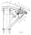
- the return line 6a opens into a lockable distribution line 71.
- a further but not lockable distribution line 72 is also supplied with distribution material 2 from the feed line 5. Both types of distribution lines 7 occur several times on the distribution head 6; the distribution lines 72 predominate.
- a connector 7a connects to an outlet 7b of the distributor lines by means of a clamp connection 7c of the distributor lines 7.
- a shut-off device 8 is provided in the connector 7a. This consists of a flap 8a which can be pivoted about a fixed axis 8b on the nozzle so that it alternately closes a branch 7d to the return line 6a and the delivery cross section of the distributor line 71. The position of the flap 8a is determined by the excitation or de-excitation of an electromagnet 8c, which can be locked in place on the clamping connection 7c.
- the distribution lines 7 finally include on the nozzle 7a attached delivery hoses 7e, which transport the material to be distributed 2 to the spreaders not visible in the drawing.
- the branch 7d opens into a funnel 6b which is stationary on the distributor head 6 and to which the return line 6a in turn connects.
- a supply air nozzle 5e is provided - in the flow direction just behind the indentation 5c - which connects the flow in the supply line 5 to the surroundings.
- the negative pressure behind the indentation 5c is sufficient to exert suction pressure on the return line 6 as well as on the surroundings, so that sufficient supply air is available through the supply air 9 to prevent a delivery cross-section from becoming blocked downstream.
- a slide 6d is also indicated in FIG. 3, with which the return line 6a can be shut off in whole or in part.
- This return line 6a can also, as shown in FIGS. 4, 4a, open into a part 5d of the feed line 5 which is connected upstream of the vertical part 5a and is designed here as a bend, for example in its horizontal section 5f;
- the flow conditions are met if the junction is preceded by a flat nozzle plate 5g instead of a retraction, which also draws the flow cross-section in a nozzle-like manner, but shifting asymmetrically towards the large radius of curvature of section 5f, where the flow velocity is highest.
- a supply air nozzle 6e is provided in this embodiment within the return line 6a.
- the rigid vertical part 5a through which the material to be distributed 2 is transported vertically upwards, as in the embodiments according to FIGS. 1 to 4, is designed with a nozzle-like retraction 5c.
- the return line 6a ends above the retraction 5c.
- a conically shaped piece of pipe 6d has been inserted in the vertical part 5a in the region of the mouth 6c of the return line 6a.
- This conical piece of pipe has a smaller diameter directed towards the retraction 5c, this being chosen such that the material to be distributed 2 is introduced into the feed line 5 in an approximately annular manner. In this way, a more favorable distribution of the returned distribution material 2 is achieved.
Landscapes
- Life Sciences & Earth Sciences (AREA)
- Soil Sciences (AREA)
- Environmental Sciences (AREA)
- Fertilizing (AREA)
- Sowing (AREA)
- Threshing Machine Elements (AREA)
Priority Applications (1)
| Application Number | Priority Date | Filing Date | Title |
|---|---|---|---|
| EP96114671A EP0752203B1 (fr) | 1993-09-11 | 1994-07-16 | Distributeur pneumatique agricole |
Applications Claiming Priority (2)
| Application Number | Priority Date | Filing Date | Title |
|---|---|---|---|
| DE9313779U DE9313779U1 (de) | 1993-09-11 | 1993-09-11 | Landwirtschaftliche pneumatische Verteilmaschine |
| DE9313779U | 1993-09-11 |
Related Child Applications (2)
| Application Number | Title | Priority Date | Filing Date |
|---|---|---|---|
| EP96114671A Division EP0752203B1 (fr) | 1993-09-11 | 1994-07-16 | Distributeur pneumatique agricole |
| EP96114671.9 Division-Into | 1996-09-13 |
Publications (2)
| Publication Number | Publication Date |
|---|---|
| EP0642729A1 true EP0642729A1 (fr) | 1995-03-15 |
| EP0642729B1 EP0642729B1 (fr) | 1997-05-14 |
Family
ID=6898009
Family Applications (2)
| Application Number | Title | Priority Date | Filing Date |
|---|---|---|---|
| EP96114671A Expired - Lifetime EP0752203B1 (fr) | 1993-09-11 | 1994-07-16 | Distributeur pneumatique agricole |
| EP94111112A Expired - Lifetime EP0642729B1 (fr) | 1993-09-11 | 1994-07-16 | Distributeur pneumatique agricole |
Family Applications Before (1)
| Application Number | Title | Priority Date | Filing Date |
|---|---|---|---|
| EP96114671A Expired - Lifetime EP0752203B1 (fr) | 1993-09-11 | 1994-07-16 | Distributeur pneumatique agricole |
Country Status (2)
| Country | Link |
|---|---|
| EP (2) | EP0752203B1 (fr) |
| DE (3) | DE9313779U1 (fr) |
Cited By (5)
| Publication number | Priority date | Publication date | Assignee | Title |
|---|---|---|---|---|
| WO1997021338A1 (fr) * | 1995-12-14 | 1997-06-19 | Crister Stark | Machine agricole |
| DE102015116378A1 (de) | 2015-09-28 | 2017-03-30 | Horsch Maschinen Gmbh | Verteilturm einer landwirtschaftlichen Verteilmaschine |
| DE102017203854A1 (de) | 2017-03-08 | 2018-09-13 | Horsch Maschinen Gmbh | Verteilerturm einer landwirtschaftlichen Maschine, landwirtschaftliche Maschine und Verfahren zum Betreiben einer solchen landwirtschaftlichen Maschine |
| DE102017113487A1 (de) | 2017-06-20 | 2018-12-20 | Amazonen-Werke H. Dreyer Gmbh & Co. Kg | Landwirtschaftliche pneumatische Verteilmaschine |
| WO2021204677A1 (fr) | 2020-04-08 | 2021-10-14 | Amazonen-Werke H. Dreyer SE & Co. KG | Machine de distribution pneumatique |
Families Citing this family (21)
| Publication number | Priority date | Publication date | Assignee | Title |
|---|---|---|---|---|
| DE4411240C2 (de) * | 1994-03-31 | 2001-12-20 | Kverneland Accord Landmaschine | Verteilerkopf für eine Verteilmaschine für Saatgut und/oder Dünger |
| DE19538626A1 (de) * | 1995-09-15 | 1997-03-20 | Amazonen Werke Dreyer H | Landwirtschaftliche Verteilmaschine |
| DE19613785C2 (de) * | 1996-04-04 | 2002-08-22 | Kverneland Accord Gmbh & Co Kg | Abluftleitung für eine pneumatisch arbeitende Verteilmaschine |
| DE19711942A1 (de) * | 1997-03-21 | 1998-09-24 | Amazonen Werke Dreyer H | Landwirtschaftliche Verteilmaschine |
| DE19745098C2 (de) * | 1997-10-11 | 2003-01-30 | Lemken Gmbh & Co Kg | Pneumatische Dillmaschine mit Saatgutrückführung |
| ATE444920T1 (de) * | 2002-12-04 | 2009-10-15 | T A C A Internat Pty Ltd | Verfahren und vorrichtung zur ausgabe von partikelförmigem material |
| DE102009003791A1 (de) * | 2009-04-16 | 2010-10-21 | Amazonen-Werke H. Dreyer Gmbh & Co. Kg | Pneumatisch arbeitende Verteilmaschine |
| DE102009031066B4 (de) | 2009-06-30 | 2015-10-01 | Lemken Gmbh & Co. Kg | Verteiler für pneumatische Drillmaschine |
| USD647542S1 (en) | 2009-09-11 | 2011-10-25 | Agco-Amity Jv, Llc | Seed brake |
| US8196534B2 (en) † | 2009-12-03 | 2012-06-12 | Deere & Company | Volumetric metering system with clutch based sectional shut-off |
| EP2717668B1 (fr) * | 2011-06-10 | 2016-04-27 | Great Plains Manufacturing, Incorporated | Tour de distribution de graines pour un semoir pneumatique |
| DE102012015731A1 (de) * | 2012-08-09 | 2014-02-13 | Alois Pöttinger Maschinenfabrik Ges.m.b.H. | Verteilerkopf für eine Sä- und/oder Düngemaschine |
| DE102013000758A1 (de) * | 2013-01-16 | 2014-07-17 | Alois Pöttinger Maschinenfabrik Ges.m.b.H. | Verteilerkopf für eine Sä- und/oder Düngemaschine |
| EA029183B1 (ru) * | 2014-06-11 | 2018-02-28 | Республиканское Унитарное Предприятие "Научно-Практический Центр Национальной Академии Наук Беларуси По Механизации Сельского Хозяйства" | Сеялка с пневматическим высевающим аппаратом |
| ITUB20152403A1 (it) * | 2015-07-22 | 2017-01-22 | Matermacc S P A | Dispositivo di distribuzione di fertilizzanti. |
| DE102016218531A1 (de) * | 2016-09-27 | 2018-03-29 | Horsch Maschinen Gmbh | Verteilturm einer landwirtschaftlichen Verteilmaschine |
| DE102017113488A1 (de) * | 2017-06-20 | 2018-12-20 | Amazonen-Werke H. Dreyer Gmbh & Co. Kg | Landwirtschaftliche pneumatische Verteilmaschine |
| DE102018102582A1 (de) * | 2018-02-06 | 2019-08-08 | Amazonen-Werke H. Dreyer Gmbh & Co. Kg | Verfahren zum Ausbringen von körnigem Material |
| DE102019128863B4 (de) * | 2019-10-25 | 2023-06-29 | Amazonen-Werke H. Dreyer SE & Co. KG | Verteilerkopf für eine pneumatisch arbeitende Verteilmaschine |
| DE102020130985A1 (de) | 2020-11-24 | 2022-05-25 | Pöttinger Landtechnik Gmbh | Verteilerkopf für eine Sä- und/oder Düngemaschine |
| CN116420470A (zh) * | 2022-01-04 | 2023-07-14 | 中国农业机械化科学研究院集团有限公司 | 气流输送式播种机及其区段控制式种/肥导流分配装置 |
Citations (3)
| Publication number | Priority date | Publication date | Assignee | Title |
|---|---|---|---|---|
| EP0376018A2 (fr) * | 1988-12-22 | 1990-07-04 | Amazonen-Werke H. Dreyer GmbH & Co. KG | Machine distributrice |
| US5028009A (en) * | 1989-12-22 | 1991-07-02 | Ag-Chem Equipment Co., Inc. | Distributor head for use with booms having shut-off capability |
| US5074228A (en) * | 1990-10-04 | 1991-12-24 | Daws Gregory R | Apparatus and methods for selectively creating tramlines |
-
1993
- 1993-09-11 DE DE9313779U patent/DE9313779U1/de not_active Expired - Lifetime
-
1994
- 1994-07-16 EP EP96114671A patent/EP0752203B1/fr not_active Expired - Lifetime
- 1994-07-16 DE DE59409523T patent/DE59409523D1/de not_active Expired - Lifetime
- 1994-07-16 EP EP94111112A patent/EP0642729B1/fr not_active Expired - Lifetime
- 1994-07-16 DE DE59402728T patent/DE59402728D1/de not_active Expired - Lifetime
Patent Citations (3)
| Publication number | Priority date | Publication date | Assignee | Title |
|---|---|---|---|---|
| EP0376018A2 (fr) * | 1988-12-22 | 1990-07-04 | Amazonen-Werke H. Dreyer GmbH & Co. KG | Machine distributrice |
| US5028009A (en) * | 1989-12-22 | 1991-07-02 | Ag-Chem Equipment Co., Inc. | Distributor head for use with booms having shut-off capability |
| US5074228A (en) * | 1990-10-04 | 1991-12-24 | Daws Gregory R | Apparatus and methods for selectively creating tramlines |
Cited By (12)
| Publication number | Priority date | Publication date | Assignee | Title |
|---|---|---|---|---|
| WO1997021338A1 (fr) * | 1995-12-14 | 1997-06-19 | Crister Stark | Machine agricole |
| DE102015116378A1 (de) | 2015-09-28 | 2017-03-30 | Horsch Maschinen Gmbh | Verteilturm einer landwirtschaftlichen Verteilmaschine |
| WO2017055266A1 (fr) * | 2015-09-28 | 2017-04-06 | Horsch Maschinen Gmbh | Tour de distribution d'une machine de distribution agricole et procédé pour la mise hors circuit en série sur une telle tour de distribution |
| EP3653036A1 (fr) | 2015-09-28 | 2020-05-20 | Horsch Maschinen GmbH | Tête de distribution pour machine de distribution agricole et procédé de désactivation des rangs d'une telle tête de distribution |
| US10779460B2 (en) | 2015-09-28 | 2020-09-22 | Horsch Maschinen Gmbh | Distributing tower of an agricultural distributing machine and method for series cut-off on such a distributing tower |
| DE102017203854A1 (de) | 2017-03-08 | 2018-09-13 | Horsch Maschinen Gmbh | Verteilerturm einer landwirtschaftlichen Maschine, landwirtschaftliche Maschine und Verfahren zum Betreiben einer solchen landwirtschaftlichen Maschine |
| DE102017113487A1 (de) | 2017-06-20 | 2018-12-20 | Amazonen-Werke H. Dreyer Gmbh & Co. Kg | Landwirtschaftliche pneumatische Verteilmaschine |
| EP3417688A1 (fr) | 2017-06-20 | 2018-12-26 | Amazonen-Werke H. Dreyer GmbH & Co. KG | Machine d'épandage pneumatique agricole |
| WO2021204677A1 (fr) | 2020-04-08 | 2021-10-14 | Amazonen-Werke H. Dreyer SE & Co. KG | Machine de distribution pneumatique |
| DE102020109791A1 (de) | 2020-04-08 | 2021-10-14 | Amazonen-Werke H. Dreyer SE & Co. KG | Pneumatische Verteilmaschine |
| EP4179859A1 (fr) | 2020-04-08 | 2023-05-17 | Amazonen-Werke H. Dreyer SE & Co. KG | Machine de distribution pneumatique |
| US12193353B2 (en) | 2020-04-08 | 2025-01-14 | Amazonen-Werke H. Dreyer SE & Co. KG | Pneumatic distribution machine |
Also Published As
| Publication number | Publication date |
|---|---|
| DE59409523D1 (de) | 2000-10-19 |
| EP0752203B1 (fr) | 2000-09-13 |
| EP0752203A3 (fr) | 1997-04-02 |
| EP0642729B1 (fr) | 1997-05-14 |
| EP0752203A2 (fr) | 1997-01-08 |
| DE9313779U1 (de) | 1993-11-18 |
| DE59402728D1 (de) | 1997-06-19 |
Similar Documents
| Publication | Publication Date | Title |
|---|---|---|
| EP0642729B1 (fr) | Distributeur pneumatique agricole | |
| EP3372064B1 (fr) | Tour de distribution d'une machine agricole, machine agricole et procédé de fonctionnement d'une telle machine agricole | |
| DE102016115236A1 (de) | Verteilmaschine und Verfahren zur Aussaat von granulatartigem Verteilgut | |
| EP2695508B1 (fr) | Tête de répartition pour une machine à semence ou à engrais | |
| EP0799560A2 (fr) | Conduite pour l'air de sortie d'un distributeur pneumatique | |
| DE102011054862A1 (de) | Bodenbearbeitungsgerät und Verfahren zur Einbringung von wasserspeicherndem Material und/oder Düngemittel und/oder Saatgut in den Erdboden | |
| DE60101108T2 (de) | Sävorrichtung und Sämaschine mit solchen Sävorrichtungen | |
| EP3417688A1 (fr) | Machine d'épandage pneumatique agricole | |
| DE2807639C2 (de) | Vorrichtung und Verfahren zum Einspritzen von körnigen Materialien in den Erdboden | |
| DD297298A5 (de) | Vorrichtung zum einbringen von samen in den boden | |
| WO2021083536A1 (fr) | Machine d'épandage pneumatique | |
| EP4230019B1 (fr) | Epandeur pneumatique d'engrais | |
| DE29517792U1 (de) | Gülleverteiler | |
| DE102020133357A1 (de) | Dosiersystem einer landwirtschaftlichen Sämaschine | |
| DE10010347A1 (de) | Vorrichtung zum Ausbringen von Gut auf landwirtschaftliche Flächen | |
| DE20306595U1 (de) | Sämaschine | |
| EP0391220A1 (fr) | Distributeur agricole | |
| DE69407113T2 (de) | Pneumatischer Sämaschine und kombinierte Landmaschine zur Bodenbearbeitung und zum Säen mit einer solchen pneumatischen Sämaschine | |
| EP4305943A1 (fr) | Dispositif de transport pneumatique d'un agent auxiliaire vers des unités en série d'un semoir | |
| EP3701780B1 (fr) | Système de semoir | |
| DE102023129737A1 (de) | Reiheneinheit einer landwirtschaftlichen Maschine und landwirtschaftliche Maschine | |
| EP4662995A1 (fr) | Machine de distribution pneumatique | |
| DE102024129278A1 (de) | Landwirtschaftliche Feldspritze und Spritzvorrichtung für eine landwirtschaftliche Feldspritze | |
| DE102022108775A1 (de) | Landwirtschaftliche Verteilmaschine | |
| EP0382006A1 (fr) | Machine distributrice combinée |
Legal Events
| Date | Code | Title | Description |
|---|---|---|---|
| PUAI | Public reference made under article 153(3) epc to a published international application that has entered the european phase |
Free format text: ORIGINAL CODE: 0009012 |
|
| AK | Designated contracting states |
Kind code of ref document: A1 Designated state(s): DE FR |
|
| 17P | Request for examination filed |
Effective date: 19950309 |
|
| GRAG | Despatch of communication of intention to grant |
Free format text: ORIGINAL CODE: EPIDOS AGRA |
|
| GRAH | Despatch of communication of intention to grant a patent |
Free format text: ORIGINAL CODE: EPIDOS IGRA |
|
| 17Q | First examination report despatched |
Effective date: 19961028 |
|
| GRAH | Despatch of communication of intention to grant a patent |
Free format text: ORIGINAL CODE: EPIDOS IGRA |
|
| GRAA | (expected) grant |
Free format text: ORIGINAL CODE: 0009210 |
|
| AK | Designated contracting states |
Kind code of ref document: B1 Designated state(s): DE FR |
|
| DX | Miscellaneous (deleted) | ||
| REF | Corresponds to: |
Ref document number: 59402728 Country of ref document: DE Date of ref document: 19970619 |
|
| ET | Fr: translation filed | ||
| PLBE | No opposition filed within time limit |
Free format text: ORIGINAL CODE: 0009261 |
|
| STAA | Information on the status of an ep patent application or granted ep patent |
Free format text: STATUS: NO OPPOSITION FILED WITHIN TIME LIMIT |
|
| 26N | No opposition filed | ||
| REG | Reference to a national code |
Ref country code: FR Ref legal event code: TP |
|
| REG | Reference to a national code |
Ref country code: FR Ref legal event code: TP |
|
| PGFP | Annual fee paid to national office [announced via postgrant information from national office to epo] |
Ref country code: DE Payment date: 20130918 Year of fee payment: 20 |
|
| PGFP | Annual fee paid to national office [announced via postgrant information from national office to epo] |
Ref country code: FR Payment date: 20130719 Year of fee payment: 20 |
|
| REG | Reference to a national code |
Ref country code: DE Ref legal event code: R071 Ref document number: 59402728 Country of ref document: DE |
|
| PG25 | Lapsed in a contracting state [announced via postgrant information from national office to epo] |
Ref country code: DE Free format text: LAPSE BECAUSE OF EXPIRATION OF PROTECTION Effective date: 20140717 |