EP0642732B1 - Boden-Bearbeitungsvorrichtung - Google Patents
Boden-Bearbeitungsvorrichtung Download PDFInfo
- Publication number
- EP0642732B1 EP0642732B1 EP94113577A EP94113577A EP0642732B1 EP 0642732 B1 EP0642732 B1 EP 0642732B1 EP 94113577 A EP94113577 A EP 94113577A EP 94113577 A EP94113577 A EP 94113577A EP 0642732 B1 EP0642732 B1 EP 0642732B1
- Authority
- EP
- European Patent Office
- Prior art keywords
- working
- implement
- additional
- chassis
- mowing
- Prior art date
- Legal status (The legal status is an assumption and is not a legal conclusion. Google has not performed a legal analysis and makes no representation as to the accuracy of the status listed.)
- Expired - Lifetime
Links
- 230000033001 locomotion Effects 0.000 claims abstract description 36
- 230000008878 coupling Effects 0.000 claims description 19
- 238000010168 coupling process Methods 0.000 claims description 19
- 238000005859 coupling reaction Methods 0.000 claims description 19
- 239000002689 soil Substances 0.000 claims description 11
- 238000005192 partition Methods 0.000 claims description 8
- 238000003860 storage Methods 0.000 claims description 4
- 238000005520 cutting process Methods 0.000 description 33
- 241000196324 Embryophyta Species 0.000 description 21
- 210000003128 head Anatomy 0.000 description 7
- 230000005540 biological transmission Effects 0.000 description 5
- 230000002093 peripheral effect Effects 0.000 description 5
- 210000002435 tendon Anatomy 0.000 description 5
- 230000008859 change Effects 0.000 description 4
- 230000000694 effects Effects 0.000 description 4
- 238000012549 training Methods 0.000 description 4
- 230000001154 acute effect Effects 0.000 description 3
- 238000010276 construction Methods 0.000 description 3
- 239000000463 material Substances 0.000 description 3
- 239000002245 particle Substances 0.000 description 3
- 244000025254 Cannabis sativa Species 0.000 description 2
- 229910000639 Spring steel Inorganic materials 0.000 description 2
- 230000006378 damage Effects 0.000 description 2
- 230000001066 destructive effect Effects 0.000 description 2
- 230000002441 reversible effect Effects 0.000 description 2
- 238000010408 sweeping Methods 0.000 description 2
- 229930091051 Arenine Natural products 0.000 description 1
- 208000012868 Overgrowth Diseases 0.000 description 1
- 208000027418 Wounds and injury Diseases 0.000 description 1
- 238000006243 chemical reaction Methods 0.000 description 1
- 239000003795 chemical substances by application Substances 0.000 description 1
- 210000000078 claw Anatomy 0.000 description 1
- 238000002485 combustion reaction Methods 0.000 description 1
- 238000013461 design Methods 0.000 description 1
- 239000013013 elastic material Substances 0.000 description 1
- 210000001061 forehead Anatomy 0.000 description 1
- 238000001746 injection moulding Methods 0.000 description 1
- 208000014674 injury Diseases 0.000 description 1
- 230000010354 integration Effects 0.000 description 1
- 238000003754 machining Methods 0.000 description 1
- 238000012423 maintenance Methods 0.000 description 1
- 230000013011 mating Effects 0.000 description 1
- 238000012986 modification Methods 0.000 description 1
- 230000004048 modification Effects 0.000 description 1
- 229920000728 polyester Polymers 0.000 description 1
- 238000003825 pressing Methods 0.000 description 1
- 238000012545 processing Methods 0.000 description 1
- 230000009467 reduction Effects 0.000 description 1
- 230000000284 resting effect Effects 0.000 description 1
- 238000009420 retrofitting Methods 0.000 description 1
- 238000005096 rolling process Methods 0.000 description 1
- 125000006850 spacer group Chemical group 0.000 description 1
- 239000004753 textile Substances 0.000 description 1
- 230000007704 transition Effects 0.000 description 1
- 238000013519 translation Methods 0.000 description 1
- 238000004804 winding Methods 0.000 description 1
Images


Classifications
-
- A—HUMAN NECESSITIES
- A01—AGRICULTURE; FORESTRY; ANIMAL HUSBANDRY; HUNTING; TRAPPING; FISHING
- A01D—HARVESTING; MOWING
- A01D42/00—Mowers convertible to apparatus for purposes other than mowing; Mowers capable of performing operations other than mowing
- A01D42/04—Soil working
-
- A—HUMAN NECESSITIES
- A01—AGRICULTURE; FORESTRY; ANIMAL HUSBANDRY; HUNTING; TRAPPING; FISHING
- A01D—HARVESTING; MOWING
- A01D2101/00—Lawn-mowers
Definitions
- the invention relates to a soil cultivation device according to the preamble of claim 1. It should in particular be of the flat construction with which lawn by Gardens are mowed so that the mowing person can use the device or guides or pushes the lawn mower in front of it or pulls behind.
- the lawnmower has a bogie or chassis with which he works self-stable can be supported on the floor in such a way that it is roughly parallel to the lateral direction or to the feed direction Tilting movements are supported securely and therefore its working tools at a constant altitude parallel to the ground or to Walking level can be moved. Lawn mower with the walking level approximately perpendicular position of the cutting tool axis are such with a position that is approximately parallel to the running plane, the cutting tool has fly knives for which no Counter tool is required. All as not preferred The training courses mentioned depend on the requirements also conceivable.
- a drive of the respective work tool via wheels of the chassis an independent one Drive preferred because then the speed of the Working movement does not depend on the speed of the feed movement depends, but possibly also without feed movement can be worked. This applies in particular to the Mowing additional work, depending on the nature the machining area of different feed speeds need. If the lawnmower has a running or Feed drive on, this is therefore useful during the continuous further work of the work tool in the speed can be controlled or switched on and off at any time.
- US-A-3 945 176 shows a soil cultivation device with a side shielded mower and one in front of it unshielded scarifier.
- US-A-3 183 653 is a soil cultivator became known in which the two Working tools of the mowing device and the scarifying device are arranged in separate housing spaces, which however have separate side walls that are spaced lie in a row.
- the scarifier runs as separate towing unit behind the lawn mower.
- the invention is also based on the object of a soil cultivation device to create what disadvantages known training or the type described avoided are and, in particular, additional work in addition to mowing with high intensity or high efficiency essentially regardless of whether or how quickly the Device in the respective feed direction compared to the Floor is moved. Furthermore, the individual work tools without retrofitting or mutual adjustment and optionally only by simple manual switching operations can be brought in and out of work.
- At least one additional tool is independent of the feed movement of the chassis can be driven and / or e.g. this together with the mower completely in one common chassis that integrates it like the mower is essentially only free in his work area, but otherwise on the front, in the upper area and / or is covered on the side so that there is a risk of injury from immediate Touch are largely avoided.
- An advantageous one structural integration also arises when a common drive or drive motor for the cutting tool and the additional tool are provided, the drive connection between the engine and the additional tool can be when the mower is mounted in the working position is or is in rotating work. That’s it possible with both work tools simultaneously or with each of the work tools work independently of the other.
- the additional tool immediately before the cutting circle diameter of the mower and / or behind a foremost housing wall or boundary the chassis' of the chassis is arranged so that despite the arrangement of the additional tools compared to a lawn mower without such an additional tool, only a very minor one Enlargement of the total length results.
- In side view can be the distance between the front wheels or the additional tool about the same as the circle diameter of the mower be the same as the corresponding distance between the rear wheels. This distance is advantageously only a fraction of the Circle radius' of the additional tool, which in turn suitably much smaller than that of the cutting tool is.
- a shield between the two working tools provided that in the deepest area and above the running level only through a single thin, upright partition can be formed and two downward open bowl or trough-shaped housings for the two work tools separates from each other.
- This positioning axis is advantageously in front of the additional tool and / or approximately at the level of the tool axis, expedient impellers with the same axis and / or one behind the other forcibly connected with each other with regard to the height adjustment or to be adjusted using a common actuating handle.
- the additional tool and in particular its working tines can through the front floor wheels of the chassis be shielded over a large area, so that they hardly have a foot of the Operator can grasp by such Wheel is overrun.
- the additional tool is opposite respective neighboring impeller but also additionally through an outermost side wall of the chassis or chassis housing shielded which the storage of the additional tool and can carry the positioning axis. Over the bottom this housing stands the additional tool at most with one Third to a quarter of its diameter. Furthermore can the wheel axis of the respective front wheel in front of Tool axis of the additional tool or closer to the flight circle diameter, which is still a better accident protection results.
- the mower expediently gearless immediately driven by the engine output shaft is for the additional tool is a gearbox instead of a separate motor provided that is driven by this motor shaft, expediently the largest distance of the gear connection is above the respective work tool.
- the mower expediently gearless immediately driven by the engine output shaft is for the additional tool is a gearbox instead of a separate motor provided that is driven by this motor shaft, expediently the largest distance of the gear connection is above the respective work tool.
- additional tools mounted in a fixed position relative to the chassis or an intermediate shaft at a distance in front of the motor output shaft be stored, which is driven by a gear stage and the additional tool via a further gear stage drives.
- gear stage is advantageous in one Gearbox arranged from the respective housing space for the work tools are essentially completely separate is, so that dirt or the like. From this housing space not in can reach the gearbox.
- the drive of the additional tool can be in the distance between the ends and / or at least at one end, the associated gear stage is also useful in one essentially separate from the housing space of the additional tool Gearbox is located.
- This gear stage can also essentially by a rotating traction element of the described Be kind.
- the clutch in advantageously arranged directly on the intermediate shaft be, expediently a gear link directly formed by the associated pulley and not a separate one Coupling link is required.
- For each Gear stage is also a round cord, a flat ribbon, a Triangular, a square or another belt conceivable, being opposite an arrangement with a tension pulley or The like.
- Tendon is provided for the tension member.
- the flexible tension member advantageously has a low positive or negative thermal expansion coefficient, in order the need for re-tensioning after certain operating times to avoid. It is also for belt tensioning conceivable, the conical engagement flanks of a deflection of the Belt axially adjustable against each other so that the associated turning radius can be changed continuously. Instead of a tension member made of a rubber-elastic material a low-stretch textile cord can also be used. Furthermore, the use of a pulling element made of polyester conceivable.
- the Invention also an advantageous embodiment of the additional tool, the appropriate working tines made of spring steel wire or a material with similar properties.
- the cross-sectional diameter of these working tines is appropriate between 0.8 to 1.2 mm.
- the additional tool can in Modular construction from individual building blocks or tool bodies be composed, all of substantially the same design and axially to each other in any order are structured.
- Each tool body can optionally be in one of eight mutually offset rotational positions on a tool or Profile shaft are placed so that it is in the respective Rotational position against this profile shaft against twisting is secured, but can be moved axially and for the rotation lock not the frontal engagement into an adjacent tool body.
- an additional tool body is also provided can be. As a result, a very even and low load on the additional tool guaranteed.
- Each tool body expediently carries several working tines in the axial direction next to each other and / or in the circumferential direction approximately diametrically offset from each other, so that e.g. each only three working tines are working at the same time reach.
- each working tine due to their resilient deflection from the floor suddenly springing back solve, have already the following in the circumferential direction as well axially immediately adjacent working tines started in Engaging with the ground to get and sort of drawn Drag tines to move along the ground.
- the axially adjacent working tines of the respective Tool body can be on a common storage or Securing member may be arranged, e.g. a rivet that Spring coils at the foot of the respective working tine as well radially projecting flanges of the associated hub body enforced and only on the one facing the tool axis Surface line on such flanges in the distance between its ends can be supported.
- the spring turns of the respective working tines can be essentially free of axial play engage between flanges of the type mentioned so that axial expansion of these spring turns is not possible is.
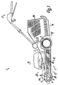
- the lawn mower 1 has an oblong rectangular top view Chassis 2 with a substantially closed housing-shaped chassis 3 on the front and rear End laterally two floor runners 4, 5, namely wheels, in essentially freely rotatable around two parallel wheel axles are stored, the two wheels 4, 5 on each side run approximately in the same lane and the rear wheels are larger Can have diameters.
- the rear wheels 5 In front of the rear wheels 5 are two working devices 6, 7 working in succession provided and on the top, on the sides and on the Front and back together through the chassis 3 in essentially completely through across both work facilities 6, 7 continuous housing wall covered.
- a scarifier 6 is provided, as an additional tool 8 trained work tool in plan view approximately extends to the rear ends of the wheels 4, the between its ends over the entire associated working width in goes through essentially continuously, and essentially symmetrical to that to the longitudinal median plane of the chassis 2 parallel center plane of the work area behind it lying cutter 9 of the mowing device 7.
- the flight circle or working area extends from above Mower 9 to a small gap distance to the rear circumference of the additional tool 8, while the rear End of this work area almost to the front End of the rear wheels 5 is enough.
- the working area of the cutting tool 9 extends to the side almost up to the associated lateral outer limits of the chassis' 3, which in the area of the wheels 4, 5 by slightly more than their wheel width are offset inwards, so that the working width of the additional tool 8 about twice this wheel width is smaller than the working width of the Mower 9 is.
- the working width of the additional tool 8 then essentially closes directly to the longitudinal edge of the strip already processed, so that a good one Efficiency results and is avoided by that Additional tool 8 stripe areas can be machined twice.
- Mower 9 is e.g. by two or more radially protruding, for Working level 14 flat plate-shaped flyknife formed.
- the working plane 13 of the additional tool parallel to the running plane 10 8 is usually lower than levels 10, 14 and is not as with the cutting tool 9 through one end face, but through the deepest point of the outer circumference of the additional tool 8 determined.
- the running level 10 and the working axis 11th approximately parallel common wheel axis 15 of the wheels 4 can be approximately at the same height as and relative to the working axis 11 be offset by an amount that is of the order of magnitude the flight circle radius' of the additional tool 8.
- a main feed direction 16 of the lawn mower 1 determines which results from the fact that the person leading the lawnmower 1 behind the lawnmower Foot goes along.
- the working axis lies in relation to the feed direction 16 11 approximately rectangular.
- the diameter of the outermost flight circle 17 of the additional tool 8 is about three quarters of the diameter of the wheels 4, so that it is not in plan view over its front ends protrudes, but by its opposite the wheels 4 Eccentric position at most to the rear and at a distance above the running level 10 via the rear ends of the wheels 4 can protrude.
- the smallest distance between the flight circle diameters of the two working tools 8, 9 is essential smaller than the diameter of the flight circle 17 and significantly smaller than the flight circle radius of the additional tool 9 and can be on the order of a fifth of the diameter of the flight circle 17 or one tenth of the flight circle radius' of the cutting tool 9, whose flight circle diameter is approximately four times the size of the additional tool 8.
- the cutting tool 9 is at the lower end of a cutting shaft 18 arranged, which on a at the top of the chassis' 3 attached motor flange 19 mounted and via a drive arrangement 20 is to be driven.
- the associated one Electric motor or an internal combustion engine formed drive motor 22 is expedient with its output shaft approximately perpendicular to the running plane 10 or in the working axis 12, see above that this output shaft directly form the mowing shaft 18 or can wear, on which the cutting tool 9 by a Forehead screw is attached easily replaceable.
- a bow-shaped guide handle 21 with their two front side Legs articulated, the above and behind the Chassis 3 form a guide handle over which the Drive arrangement 20 can be switched on and off. It is useful for the operation of the drive arrangement 20 with the guide handle at the same time a safety handle hold an on position so that when you release the Guide handle inevitably released this handle and is automatically transferred to its off position an immediate standstill or a drive interruption the work tools 8, 9 results.
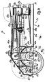
- the mowing shaft has directly below the drive motor 22 18 to form a pulley 23 a in cross section e.g. trapezoidal circumferential groove, and from this pulley 23, the additional tool 8 can be driven via a gear 24 become.
- the single-stage gear 24 has two at an angle gear sections 25, 26 lying to each other, which by an intermediate shaft 27 are offset against each other.
- This Intermediate shaft 27 carries above the additional tool 8 and slightly offset to the rear, but in front the cutting tool 9, two axially adjacent and independently rotating pulleys 28, 29.
- a corresponding pulley 31 is at a distance between the Ends of the additional tool 8 or approximately in the middle of its length arranged. From the pulley 23 is continuous up to the pulley 31 a rotating drive belt 32, e.g.
- the intermediate shaft 27 is perpendicular to the output shaft 18 or parallel to the working axis 11, so that the gear 24 according to Art an angular gear works.
- the pulleys 28, 29 can on a common shaft or axis with bearings 34 be stored.
- the chassis 3 forms one from the front to the rear end of the lawnmower 1 through housing 35, which, however separate housing spaces limited.
- the gear 24 is in the arranged essentially in a gearbox 36, which is shown in Fig. 3 shown open and opposite the work tools 8, 9 is essentially closed or only open where the output shaft 18 or leading to the additional tool 8 Drive connections are made.
- the additional tool 8 is arranged in a separate housing space 37, the lies below the front end of the gear chamber 36 and is essentially only open in the shape of a cup.
- Right away behind the housing space 37 includes a housing space 38 lying at the rear end of the gearbox 36 for receiving the cutting tool 9, which is also in the described essentially only downward cup-shaped is open.
- the housing space 37 is upright Front wall 39 delimits the foremost end of the Chassis' 3 or the lawnmower 1 can form.
- the two Housing spaces 37, 38 are through an upright partition 40 or corresponding release agents separated from each other only up to a gap between the two flight circle diameters the work tools 8, 9 are adjacent and approximate over the entire working width of the working tool 8 or 9 stretches continuously and closed.
- Of the Housing space 7 is at the top of an approximately horizontal Cover wall 41 delimits which is the bottom wall of the gear chamber 36 forms and except for an opening Execution of the drive connection is closed.
- the top wall 42 also has the housing space 38, with an opening in this top wall 42 passes through the mowing shaft 18 is.
- the gear box 36 is through a hood-shaped, non-destructive, easily detachable and complete removable and / or hinged cover 44 closed, which overlaps both housing spaces 37, 38 and sits on the top walls 41, 42 with their hood edge.
- the cover 44 has an opening or a Cutout for the implementation of the drive belt 32.
- the deflection pulleys 28, which are rotatable about the deflection axis 43, 29 reach almost to the top with their lower parting the top wall 41 and with its upper apex approximately to the inside of the top wall of the cover 44, so that the Lawn mower 1 in its front, in front of the drive motor 22 lying area can be kept so flat that this Area also under relatively low shrubbery or Driven and processed there with the work device 6 can be.
- a clutch 30 is provided in the form of a friction clutch, whose coupling links essentially by Pulley 23 and the drive belt 32 can be formed.
- the drive belt 32 can be tensioned under its weight from the annular groove provided as a coupling member 45
- Belt wheel 23 with radial expansion axially downwards slide a tray, which the cutting shaft 18 in the gap distance at least partially surrounds.
- Actuating device 46 is provided, with which as a belt tendons acting pulleys 28, 29 transverse to the axis of the coupling member 45 and to its deflection axis 43 approximately in Longitudinal direction of the lawnmower 1 can be adjusted.
- a handle 47 For adjustment is in the area of the handle Guide handle 21, a handle 47 is provided which over a Traction element, like a Bowden cable, with a pulley 28, 29 carrying, sliding carriage is connected. This slide is approximately parallel to a guide 52 Running level 10 slidably mounted against spring force, wherein the spring force can act so that it on the drive belt 32nd always has a tensioning effect if the clutch 30 is engaged is. the pulleys 28, 29 using the Handle 47 adjusted in the direction of the coupling member 45, so the drive belt 32 slides out of the coupling member 45 onto the Filing.
- a Traction element like a Bowden cable
- the housing rooms 37, 38 are on both sides bounded laterally by side walls 48, which on the outside of the chassis, namely in the narrower area of the Additional tool 8 immediately adjacent to the inside the wheels 4 and in the widened area of the cutting tool 9 in the longitudinal direction between the wheels 4, 5.
- each wheel is 4 or 5 on a between its inside and the associated side wall 48 lying Handlebar 54 rotatably mounted, which in turn about the central axis an actuating shaft 53 parallel to the wheel axis 15 the chassis 3 is pivotable.
- the central axis of this Actuating shaft 53 lies in front of the wheel axle in every setting state 15, a short distance from the flight circle 17 and approximately in Height of the working axis 11, the actuating shaft 53 in bearings is rotatably mounted, which is provided in the side walls 48 are.
- the respective control shaft 53 connects the two links 54 of the associated wheels 4 and 5, so that both Handlebar 54 are pivoted in unison.
- the two work tools 8, 9 can also be completely independent be drivable from each other, e.g. through separate Motors and / or in that both working tools 6, 7 via separate clutches to the output shaft of the Drive motor 22 can be coupled disengageable.
- a separate motor for the work tool 8 can this in front of the drive motor 22, laterally adjacent to Working tool 8 in a separate housing space, inside of the roll core of the working tool 8 as an axis motor or coaxial with the working tool 8 and / or at least partially arranged immediately above the flight circle 17 as well as a disc-shaped flat motor or as a rotary motor be trained, the housing with the additional tool 8th circulates.
- An actuator for height adjustment can also be useful of the additional tool 8 relative to the chassis 3 be provided, between the height adjustment device 50 and the bearings of the additional tool 8 a possibly disengageable or mechanical setting connection can be provided, through which the additional tool 8 runs approximately in sync with the Wheels 4, 5 to be adjusted relative to the chassis 3.
- the additional tool is adjustable 8 compared to the chassis 3 could be the at least one redirection 28 and 29 also as a voltage compensation element for the Drive belts 32 are used or to achieve a substantially always the same tension of the drive belt 32 at each Setting a separate one on one or more dreams of the drive belt 32 running tendon may be provided, which transversely to the respective strand resiliently in both opposite Readjust directions automatically.
- Figures 4 to 12 are mutually corresponding parts the same reference numerals as in Figures 1 to 3, however used with different letter indices, which is why all parts of the description analogously for all embodiments apply and all features or arrangements of the respective Embodiment additionally or alternatively also in each case at least one further embodiment can be provided can.
- the embodiments according to FIGS. 4 to 12 are in the, individual figures with minor modifications shown.
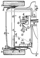
- gear 24a While in the embodiment according to Figures 1 to 3 Gear 24 only one stage, but in side view with two on both sides of the deflections 28, 29 at an angle to one another horizontal railway lines of the transmission member 32 are formed the gear 24a has two gear stages 25a, 26a an intermediate shaft 27a and separate transmission elements or drive belts 32a, 33.
- the at least over half the length of the working tool 8a intermediate shaft 27a is mounted in bearings 34a which are on the top wall 41a or 42a are fastened and of which the respective proportion close to the associated deflection 28a or 29a lies.
- the pulley 28a lies approximately in the middle Transverse plane of the additional tool 8a, while the pulley 29a laterally opposite the associated end of the additional tool 8a is slightly offset to the outside, so that instead a center drive according to FIG. 2, a side drive is provided which is laterally outside the side wall 48a with the Shaft of the additional tool 8a rotatably via the rotor 31a connected is.
- the associated gear stage 26a is essentially in a shaft of the gear compartment not shown in FIG. 5 36a, this shaft in a side view according to FIG Fig. 4 can be narrower than the housing space 37a.
- the transmission space can also be much narrower shaft 57 36a be reduced in the area of the transmission element 32a, this shaft 57 aligned with the rotor 28a approximately in the middle of the width of the chassis' 3 at the top of the Cover wall 42a led to the runner 23 and after opening the Lid 44a is open at the top.
- each bearing 58, 59 is in a divided carrier shell of the chassis 3a attached, the lower, in Fig. 6, Non-destructively easily removable support shells not shown which are the lower peripheral region of the outer rings of the Bearing 58, 59 surround and can form an assembly, which the shaft space at the bottom of the pulley 31a closes. After removing these lower trays, this can be done Additional tool 8a possibly together with the pulley 31a be lifted down from the chassis 3a and released.
- the side wall 48a In the area of the gear shaft for gear stage 26a the side wall 48a is double-walled, the outer wall part the associated lateral and to the in Fig. 6 not Wheel 4a shown in more detail adjacent to the outside of the Chassis' 3a forms.
- Each of the two wall parts carries one of the bearings 58, 59 and forms a corresponding support shell 61.
- the support shells 61 and the associated counter shells also in the manner of sliding carriages in guides of the associated wall parts 48a approximately at right angles be slidably guided to the running level 10a, so that this adjustment as well as all the others described in can be done essentially continuously.
- the bearing 59a can be in corresponding divided carrier shells Sidewall 48a attached and therefore also in the described Be detachable in such a way that both wheels 4a together with the links 54a and the control shaft 53a from Chassis 3a can be removed.
- Both tools can achieve optimal work results independently of each other as well as independently from each other against the chassis or chassis or Floor contact surfaces of the wheels or runners are continuously height-adjustable and fixable in the position set be arranged.
- FIG. 5 is a bearing housing for the pulley 31a shown, which laterally outwards close to the Inside of the adjacent wheel 4a via the side wall 48a protrudes and inside slightly over the inside this side wall 48a protrudes. Between the two parts of these lying parallel and at a distance from one another Sidewall 48a can provide the drive connection to the intermediate shaft Go through 27a. Stands over the inside of the position housing the coupling mandrel 60 before, which is expediently one of the cylindrical Training has different profile shape, so that he only by axially plugging together in several rotational positions are connected to the additional tool 8a in a rotationally locking manner can.
- the respective end of the additional tool 8a is expediently sufficient with the smallest gap distance directly to the inside the associated side wall 48a or the associated support shell 61, so that it is avoided that plant parts between these two surfaces on the shaft or the coupling mandrel 60 of the work tool 8a can wind up.
- This winding protection can also be improved in that the inside of the side wall 48a the end of the auxiliary tool 8a at least on part of its circumference a collar closely surrounding which parts of the plant against radial rejects inward movements.
- the housing space 37a is instead of essentially flat or 4 here arcuate or approximately limited over 180 ° following the flight circle 17a, for which the Cover wall 41a is trough-shaped in cross section.
- Opposite one Direction of rotation in the feed direction 16a is a direction of rotation 63 of the additional tool 8a in its lower working area against the feed direction 16a or in the direction of the cutting tool 7a to be preferred.
- Working axis 11a slightly compared to the central axis of the Channel shape of the housing space 37a so offset that the working axis 11a slightly closer to the partition 40a than lies at the front wall 39a.
- the lower edge of the partition 40a is approximately at the level of Working axis 11a or less than one fifth of the flight circle diameter 17a underneath, so that it serves as a scraper for Plant parts can be used by the additional tool 8a be taken up.
- the front wall 39a and the partition 40a form the legs of the U-shaped in cross section Limitation of the housing space 37a and are above the Connection area with the top wall 41a approximately up to Extends the height of the approximately flat top wall 42a, which connects approximately parallel to the running plane 10a and / or in height the apex of the top wall 41a.
- the side of the partition 40a and the mower facing 9a if necessary, the side facing away from it can also move around the working axis 12a be curved so that the cutting tool 9a at least over a part of its circumference in a cup-shaped to its Flight circle adapted housing space 38a.
- the coat of the Housing wall can be in the area of a device 16a rectangular axial plane of the working axis 12a in one piece connect to the inside of the side walls 48a, and its The lower edge, like that of the partition 40a, can be slightly above the lower edge 51a of the side walls 48a. This lower edge 51a points from the housing space 38a to the Area of the bearing 59a or until approximately constant before this Distance to the running level 10a and only then increases at an acute angle to form the raised lower edge 49a.
- the clutch 30a arranged on the intermediate shaft 27a has an axially displaceable on the intermediate shaft 27a Coupling member 45a, which is immediately adjacent to one Front side of the drive rotor 28a, which is also the Counter coupling member can form.
- the actuator 46a has an angular control lever 66, one of which Leg in the area of its end with a pressure member, such as a pressure roller on the side facing away from the mating coupling element Front side of the coupling member 45a rests on the other leg a tendon, like a tensioning eccentric, rests and between his legs around one to the central axis the clutch 30a rectangular axis on Chassis 3a is stored.
- the tendon is connected to the handle 47a, so that with the transmission member 66 can be pivoted so that that the coupling member 45a either against spring force in Coupling engagement pressed against the pulley 28a or released by the pressure member and thus under the spring force is lifted off the pulley 28a in the disengaged position.
- the two strands of the drive belt run from the pulley 28a 32a with a corresponding entanglement to one another turned away peripheral sides of the pulley 23a, so that they in the area of the two pulleys 23a, 28a to each other approximately rectangular levels.
- the lawn mower 1 can also advantageously one Have drive 67, via which e.g. only the rear Wheels 5 on and off manually from the guide handle 21 disengageable or controllable in speed by motor can be driven.
- a separate one Traction motor is driven by the drive motor 22 too to prefer.
- the output or Mowing shaft 18a between the drive rotor 23a and the cutting tool 9a a further drive rotor 68 in the form, for example provided a pulley, one of which is not closer illustrated drive belt to the rear to a gear arrangement or a pulley over which the Wheels 5 are driven.
- the translation is like this chosen that at at least one feed rate
- the peripheral speed is greater in the area of the flight circle 17a than the feed speed or the peripheral speed of the treads of the driven wheels 5 is one backward relative speed of the working or Engagement area of the additional tool 8a compared to the To ensure soil.
- the additional tool 8a can, depending on the requirements, be in the ground engaging tool members 69 and 70 oscillating stored flat material or flat belt tines according to Figures 1 to 3, 11 and 12 and / or resilient or have curved wire tines according to Figures 6 to 10.
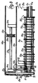
- the additional tool 8 has a hollow or through a Section of a tubular profile formed shaft 71, which belongs to the roller core 72 and the one hub body 73 Kundststoff or the like.
- a Section of a tubular profile formed shaft 71 which belongs to the roller core 72 and the one hub body 73 Kundststoff or the like.
- the hub body 73 In the circumference of the hub body 73 are slit-shaped distributed over its length and circumference Recordings 74 provided for the working tines 69, which at least about half of the cylindrical envelope surface of the roller core 72 protrude radially above this and their Flat cross sections in approximately perpendicular to the working axis 11 Levels.
- the axial distance between adjacent tine levels is suitably less than 20 mm and in the order of 10 mm, the diameter of the flight circle 17 advantageously at least 10 cm and at most 14 or 16 cm and preferably is about 12 cm.
- Each working tine 69 is on their inner, essentially free of axial play in the receptacle 74 lying end of a securing member 77, e.g. one Bolt, interspersed, on which they to one Working axis 11 approximately parallel axis around a predetermined one Swing the angular dimension back and forth as well as by using the Rotation centrifugal forces occur automatically radially can align.
- Each receptacle 74 is between two through the Hub body 73 formed hub flanges 75, which Ring flanges or only extending over a partial circumference Can be projections so that each working tine 69 with a separate securing member 77 is to be attached.
- Working tines lying axially adjacent to each other 69 are from one end of the roller core 72 and Additional tool 8 to the other end continuously against each other angularly offset about the working axis 11, so that at the respective circumferential location of the additional tool 8 only there are one or two free ends of the working tines.
- the front in the direction of rotation 63 Narrow edges of the working tines 69 at their ends by concave curved cutouts to form sharp-edged edges 79 trained so that they are not only a blunt in the ground Have a clearing effect, but cut into the floor like a groove and can reach under the plant parts.
- the roll core 72 has a continuous hub opening 76 into which the Wave 71 e.g. interlockingly engages through injection molding.
- the coupling mandrel 60 of the drive can e.g. a protruding one Have coupling element 78, such as a pin, when the roller core 72 is plugged into a transverse slot the shaft 71 and thereby the positive rotary connection manufactures.
- 11 is for the Center drive according to Figures 1 to 3 provided, wherein two such roller bodies on both sides of the drive pulley 31 and then axially directly at the end faces be strung together so that there is an effective total length of the additional tool 8 of at least 30 to 40 cm results because also on the exposed end or end faces of the hub body 73 working tines 69 are arranged, the not in slit-shaped receptacles flanked on both sides 74 lie.
- the additional tool 8a is made of a A plurality of the same or interchangeable as desired Tool body 80 formed, the hub opening 76a formed so is that it is connected to the shaft 71a in the manner of a splined connection each in a certain number of rotational positions can be put together, the angular distance essentially the same between all adjacent rotational positions is. If you divide this angular distance by 360 °, you get a number of angular divisions, and compared to this Number is the number of those arranged on the shaft 71a Tool body 80 larger by a tool body. Because here Angular distances are 45 °, so there are nine tool bodies 80 over the entire working width of the additional tool 8a strung together.
- the shaft 71a is in the outside and / or inside cross section substantially square, and the hub opening 76a instructs this outer cross-section also closely adapted to square Basic shape, with again in the middle of each square side an angular recess is provided as they are results in two regular and equal polygons around the Half of the arc angle of each polygon side against each other be twisted on top of each other. If you divide 360 ° by Half of this arc angle results in the number of possible rotational positions.
- the hub body 73a On the hub body 73a are next to each other in the axial direction at least two or at most four or six, in particular three essentially identical working tines 70 are arranged, being two on both sides of the working axis 11a roughly the same rows with opposite freely protruding Working tines 70 are provided.
- the working tines 70 of the two rows can be axially offset from each other, so that one working tine in a row in a tine plane rotates roughly halfway between neighboring ones Working tines 70 of the other row.
- the hub flanges 75 are in this case as ring flanges formed, expediently between two adjacent as well as in the outside diameter and / or in the thickness larger ring flanges in the middle a smaller ring flange is provided, which two adjacent, annular groove Separates recordings 74a.
- the axially outermost of the Larger hub flanges 75a are of each other aligned holes interspersed during the or the intermediate larger hub flanges instead of one Bore a U-shaped notch starting from the outer circumference can have.
- the securing member which is designed as a hollow rivet, is inserted into the bores 77a inserted without radial play, after which its Ends widened to form rivet heads so that they can be attached to the facing end faces of the outermost hub flanges 75a rest without axial play.
- the radially inner surface line of the securing member 77a can then on the peripheral surfaces the smaller hub flanges are essentially free of play be additionally supported.
- the respective working tine 70 is made of spring steel wire or Bent and forms in the area of attachment to the hub body 73a a spring body 81 in that the wire a torsion spring with axially close to each other lying turns is formed.
- This spring body 81 fits essentially without axial play in the associated receptacle 74a and essentially free of radial play on the securing member 77a, the direction of the helix pitch being selected that when the tine end 79a is loaded against the direction of rotation 63 the spring body 81 is loaded in the direction of a narrowing and thus with increasing friction around the circumference of the securing member 77a closes.
- One end of the spring body 81 sits tangentially in the associated working tine 70 continues while its other end tangentially into one opposite, but in an axial view according to FIG. 7 with the transition section of the working tine 70 approximately aligned Support leg 82 merges, which like the working tine 70th on the front side of the spring body in the direction of rotation 63 81 lies.
- the working tine 70 is located on one end face of a larger hub flange 75a, while the support leg 82 on the opposite end of a smaller one Hub flange rests.
- the Thickness of the larger hub flanges 75a is expedient approximately in the The magnitude of the width of a receptacle 74a is and also the smaller hub flanges can have this thickness.
- the spring body 81 of the two rows depending on the same or opposite helix slopes exhibit.
- the front of this head roughly in the plane of the associated one End face of the hub body 73a may lie.
- the one of them removed head of the securing member 77a is appropriate sunk in the outer face of the associated outermost Hubflansches 75a, which also in this end face associated end face of the hub body 73a can lie on which is the next tool body 80 immediately toast or with the interposition of an intermediate or Spacer ring connects.
- the working tine 70 is at its front in the direction of rotation 63 Page continuously over its entire free length concave with a radius of curvature that is at least so big as or bigger than this length and smaller than that Is double this length. Put it through the free end 79a the working tine 70 an axial plane of the working axis 11a, so lies the entire, freely projecting part of the working tine 70 behind this axial plane, the free end with this Axial plane an acute, which opens to the roller core 72a Includes angles of less than 90 or 30 ° and more than 10 °.
- Working tine 70 springing back by widening its curvature dodge, where appropriate then from the support surface 83 takes off, but returns like a whip when released.
- the additional tools or tines preferably have a tension-free one Empty movement along an empty path parallel to yours Working or the feed direction, in the transverse direction of the Tool or in one direction essentially rectangular to the feed direction, but parallel to the running plane and / or in an inclination direction transverse to the longitudinal direction of the Tines or the like or sideways with respect to the labor movement.
- the respective empty movement is positive by stops limited, which on the hub body 73a and / or on the hub flange 75a are provided, the counter member for these stop surfaces preferably only the support leg 82 and not that Tine is 70, although this would also be possible.
- movement game individually and separately for each of the Work tools 70 provided, and the movement game can essentially between at least 2 ° to 5 ° and at most 40 ° to 50 °, with the play in the circumferential direction expediently larger than the axial or lateral Tilt play is.
- movement games together can cause a corresponding radial movement play between the inner circumference of the hub or spring body 81 and the outer circumference of the securing member 77a and at the same time an axial movement of the hub body 81 between the associated side flanges 75a and opposite the link 77a may be provided.
- the leg 82 can essentially with its free end protrude in the same direction as the work leg 70 and can be moved backwards against the working direction opposite the radially inner main section of the leg 70 at an acute or obtuse angle to its free End diverge, which is larger than the specified game movement angle are, the angle expediently at least 30 ° and at most 90 °, in particular about 45 °. Meets the working end of the tool 70 during its working or Feed movement on a resistance, like the floor, so the abutment surfaces mentioned come in a form-fitting manner Stop engagement, and the tool is against this engagement resistance biased.
- the deflected Tool If after that the deflected Tool comes out of engagement with the resistance, it returns under tension in a reverse direction, however not immediately countered accordingly by the return energy excited because it is free on the mentioned empty path move and free the energy only by friction can give up until it moves through positive Return stop is stopped.
- the flight circle of the tool 8a can be self-resetting among the change occurring workloads.
- FIG. 9 The arrangement according to FIG. 9 is for the center drive according to FIG. 2 provided, wherein it can be seen that the shaft 36b for the Recording the drive belt 33b and the pulley 31b the bottom is closed.
- the roller core 72b is through lined up, ring-shaped and essentially The same hub body 73b is formed, which on the shaft 71b are placed directly next to each other and 74b each for only two oppositely protruding Form working tines 70b.
- These shots 74b are each between two abutting or resting against each other End faces of two adjacent hub bodies 73b limited, with a recording well only in one End face is provided while the other end face is consistently flat or smooth.
- the on working tines provided at the extreme ends of the roller core 72b 70b are fastened with pan head screws, which following the disc-shaped head a close to the Internal width and the length of the spring body 81b adapted have thread-free centering section.
- adjacent working tines can be seen in axial view 70b also different circumferential distances from one another to have.
- Working tines 70b also go from the outer circumference here of the roller core 72b approximately straight, the Ends 79b at an obtuse angle and in turn are straightforward. This allows the ends 79b to circulate put on the ground, after which they are springy Giving in of the other working tine 70b in this further course changing transverse position dragged through the ground until they are under the reach of the co-moving Spring plant parts back into their starting position in the direction of rotation and this plant parts towards the mower Throw 9 or 9a.
- the lawn mower can move both in the feed direction 16 as well as against the feed direction 16 by the operator pushed or pulled, and he can too by pressing down or lifting the guide handle 21 with its front wheels 4 and its rear wheels 5 slightly raised and then still in contact with the ground located wheels as a pivoting zone around a running plane 10 right-angled axis.
- Scarifying and mowing at the same time is advisable driven in the feed direction 16, so that first from the Plant parts to be cleared from the soil by the scarifier 6 added and either in the work area of subsequent mowing device 7 filed or immediately in the cutting tool 9 are thrown. This then takes the Plant parts together with the plant parts cut by him and leads them to a collection container in the shortest possible way 84 too, which is removable as a whole at the rear end of the Chassis' 3 is attached.
- the mower or additional tool is a conveyor, like a Flow or air conveyors assigned, e.g. by that Mowing tool is designed as a conveyor fan, which from Particle emitted particles via a throwing motion takes over, with the or all particles not in immediate Have to come into contact with the delivery fan, but one Air flow are passed, which by the conveyor fan or the additional tool is generated so that it is another Get kinetic energy imparted to the throwing motion away of additional and mowing tools in an immediately following one second lane towards or up to a last one Continue outlet of the implement or lawnmower.
- Mowing tool is designed as a conveyor fan, which from Particle emitted particles via a throwing motion takes over, with the or all particles not in immediate Have to come into contact with the delivery fan, but one Air flow are passed, which by the conveyor fan or the additional tool is generated so that it is another Get kinetic energy imparted to the throwing motion away of additional and mowing tools in an immediately following one second lane towards or up to a last one Continue outlet of the implement or lawn
- the ends of cutting blades of the cutting tool lower and / or upper fan surfaces at an angle to their Form the plane of movement or the parallel running plane, these flow-generating surfaces being curved End sections of the cutter arms can be formed, which at the same time also form cutting edges which are essentially continuously in the remaining cutting edge of the associated Mower arms go over or lie in their plane.
- a fan rotor can also be separated from at least one of the above Tools are provided, but is expedient on the same driven axis like this tool or axially immediately adjacent to and in this tool Chamber arranged like this.
- the scarifier 6 is also suitable, possibly to lay up plant parts without detaching from the ground, so that the mower 9 these plant parts can better grasp when cutting.
- the working level 13 of the scarifying device 6 can be about 5 mm or lie at least 10 to 20 mm below the running level 10.
- the speed of the additional tool 6 can be at least 2000 to approximately 3000 revolutions per minute, which makes the mentioned effects can be further improved and it it is possible to use the additional tool as a sweeping tool or train as a brush roller.
Landscapes
- Life Sciences & Earth Sciences (AREA)
- Soil Sciences (AREA)
- Environmental Sciences (AREA)
- Harvester Elements (AREA)
- Soil Working Implements (AREA)
- Fertilizers (AREA)
- Agricultural Machines (AREA)
Description
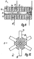
- Fig. 1
- eine erfindungsgemäße Vorrichtung in Seitenansicht,
- Fig. 2
- den Rasenmäher gemäß Fig. 1 in Draufsicht,
- Fig. 3
- einen Längsschnitt durch einen Teil des Rasenmähers gemäß Fig. 2,
- Fig. 4
- eine weitere Ausführungsform in einer Darstellung entsprechend Fig. 3,
- Fig. 5
- einen Ausschnitt des Rasenmähers gemäß Fig. 4 in teilweise geöffneter Draufsicht,
- Fig. 6
- einen Schnitt durch den Rasenmäher gemäß Fig. 5,
- Fig. 7
- ein Zusatzwerkzeug in Axialansicht,
- Fig. 8
- einen Axialschnitt durch das Zusatzwerkzeug gemäß Fig. 7,
- Fig. 9
- eine weitere Ausführungsform in einer Darstellung entsprechend Fig. 6,
- Fig. 10
- das Zusatzwerkzeug gemäß Fig. 9 in Axialansicht,
- Fig. 11
- eine weitere Ausführungsform eines Zusatzwerkzeuges im Axialschnitt und
- Fig. 12
- das Zusatzwerkzeug gemäß Fig. 11 in Axialansicht.
Claims (10)
- Boden-Bearbeitungsvorrichtung, insbesondere Rasenmäher (1), mit einem eine Laufebene (10) und/oder eine Haupt-Vorschubrichtung (16) bestimmenden Gestell (2), mindestens zwei für das gleichzeitige Arbeiten ausgebildeten Arbeitseinrichtungen (6, 7), nämlich einer Mäheinrichtung (7) und einer Boden-Bearbeitungseinrichtung, wie einer Vertikutiereinrichtung (6), die zur Durchführung ihrer Arbeitsbewegungen in getrennten ersten und zweiten Gehäuseräumen (37, 38) gelagerte und Arbeitsbereiche bestimmende erste und zweite Arbeitswerkzeuge (8, 9), wie wenigstens ein Bodenbearbeitungs-Zusatzwerkzeug (8) und mindestens ein Mähwerkzeug (9), enthalten, sowie mit einem Gehäuse (35), das eine Seitenwandung (48) für den zweiten Gehäuseraum (38) aufweist, dadurch gekennzeichnet, daß die Seitenwandung (48) auch im Bereich des ersten Werkzeuges (8) liegt.
- Vorrichtung nach Anspruch 1, dadurch gekennzeichnet, daß sie eine Antriebsanordnung (20) zum Antrieb mindestens eines der Arbeitswerkzeuge (8, 9) im wesentlichen unabhängig von der Vorschubbewegung des Fahrgestelles (2) aufweist, daß insbesondere mindestens zwei Arbeitswerkzeuge (8, 9) wenigstens zweier Arbeitseinrichtungen (6, 7) in integrierter Anordnung gemeinsam an dem Fahrgestell (2) angeordnet sind sowie wenigstens ein Zusatzwerkzeug (8) von der Antriebsanordnung (20) antreibbar ist, und daß vorzugsweise zwei Arbeitswerkzeuge (8, 9) in Vorschubrichtung (16) unmittelbar benachbart hintereinander angeordnet sind, und/oder daß in Ansicht auf die Laufebene (10) der Abstand zwischen Arbeitswerkzeugen (8, 9) kleiner als der Arbeitsdurchmesser bzw. Arbeitsradius eines Zusatzwerkzeuges (8) ist, daß insbesondere zwei Arbeitswerkzeuge (8, 9) unmittelbar benachbart zu beiden voneinander abgekehrten Seiten einer einzigen zwischenabschirmung (40) liegen, und daß vorzugsweise die Arbeitswerkzeuge (8, 9) annähernd rechtwinklig zueinander liegende Arbeitsachsen (11, 12) aufweisen.
- Vorrichtung nach Anspruch 1 oder 2, dadurch gekennzeichnet, daß wahlweise mindestens zwei Arbeitswerkzeuge (8, 9) im wesentlichen unabhängig voneinander in Arbeitseingriff bringbar sind, daß insbesondere der Arbeitsbereich eines Zusatzwerkzeuges (8) in eine gegenüber der Laufebene (10) tiefere Lage überführbar ist und daß vorzugsweise wenigstens ein Arbeitswerkzeug (8, 9) unabhängig von einem weiteren Arbeitswerkzeug (9, 8) antreibbar ist, und/oder daß mindestens zwei Arbeitswerkzeuge (8, 9) zur Verstellung ihrer Arbeitsebenen (13, 14) mit einer Höhen-Verstelleinrichtung (50) gemeinsam gegenüber der Laufebene (10) verstellbar sind, daß insbesondere an einem Fahrgestell (2) zur eigenstabilen Bodenabstützung im Arbeitszustand beider Arbeitswerkzeuge (8, 9) Bodenläufer (4, 5), wie Räder, vorgesehen sowie im wesentlichen alle Bodenläufer (4, 5) gegenüber einem die Arbeitswerkzeuge (8, 9) und die Antriebsanordnung (20) tragenden Chasses (3) des Fahrgestelles (2) höhenverstellbar sind und daß vorzugsweise mindestens zwei Arbeitswerkzeuge (8, 9) über gleiche Stellwege gegenüber der Laufebene (10) verstellbar sind, wobei vordere und hintere Bodenläufer (4, 5) zwangsverbunden gemeinsam gegenüber dem Chassis (3) verstellbar sind.
- Vorrichtung nach einem der vorhergehenden Ansprüche, dadurch gekennzeichnet, daß mindestens ein Bodenläufer (4, 5) des Gestelles (2) um mindestens eine Stellachse (53) verstellbar ist, daß insbesondere eine Stellachse (53) für einen Bodenläufer (4) des Gestelles (2) in Vorschubrichtung (16) im Abstand vom bzw. vor dem Zusatzwerkzeug (8) vorgesehen ist bzw. etwa in Höhe von dessen Arbeitsachse (11) liegt, und daß vorzugsweise eine Radachse (15) des jeweiligen Bodenläufers (4, 5) über bzw. unter die Arbeitsachse (11) des in Arbeitslage befindlichen Zusatzwerkzeuges (8) einstellbar ist, und/oder daß der tiefste Arbeitsbereich mindestens eines Zusatzwerkzeuges (8) hinter dem vorderen Boden-Abstützbereich des Gestelles (2) liegt, daß insbesondere das Zusatzwerkzeug (8) zwischen vordere seitliche, für den Mähbetrieb vorgesehene Bodenläufer (4) des Gestelles (2) eingreift bzw. wenigstens teilweise nach hinten über die Bodenläufer (4) hinausragt, und daß vorzugsweise hintere, seitliche sowie hinter dem Mähwerkzeug (9) liegende Bodenläufer (5) in Seitenansicht annähernd bis an den Arbeitsbereich eines Mähwerkzeuges (9) reichen.
- Vorrichtung nach einem der vorhergehenden Ansprüche, dadurch gekennzeichnet, daß mindestens zwei Arbeitswerkzeuge (8, 9) an der Oberseite bzw. seitlich im wesentlichen vollständig abgeschirmt in mindestens einem nach unten offenen Gehäuseraum (37, 38) angeordnet sind, daß insbesondere für mindestens zwei Arbeitswerkzeuge (8, 9) ein gemeinsames Gehäuse (35) mit einer einzigen aufrechten Trennwand (40) zur Unterteilung zweier hintereinander liegender Gehäuseräume (37, 38) vorgesehen ist, und daß vorzugsweise ein Zusatzwerkzeug (8) an seinem Umfang bogenförmig von einer Deckwand (41a) umgeben ist, und/oder daß ein Mähwerkzeug (9) unmittelbar mit einem Antriebsmotor (22) antriebsverbunden und dieser auch zum Antrieb eines Zusatzwerkzeuges (8) vorgesehen ist, daß insbesondere eine Abtriebswelle (18) eines Antriebsmotors (22) bzw. eine Mähwelle (18) eines Mähwerkzeuges (9) über ein wenigstens teilweise oberhalb eines Zusatzwerkzeuges (8) liegendes Getriebe (24) mit dem Zusatzwerkzeug (8) antriebsverbunden ist und daß vorzugsweise das Getriebe (24) im wesentlichen in einem von wenigstens einem der Arbeitswerkzeuge (8, 9) gesonderten Getrieberaum (36) liegt bzw. über eine obere, abnehmbare Gehäuseabdeckung (44 ) zugänglich ist.
- Vorrichtung nach einem der vorhergehenden Ansprüche, dadurch gekennzeichnet, daß ein Zusatzwerkzeug (8a) über ein mindestens zweistufiges Getriebe (24a) angetrieben ist, daß insbesondere im wesentlichen oberhalb eines Zusatzwerkzeuges (8a) eine zu diesem etwa parallele Zwischenwelle (27a) gelagert ist und daß vorzugsweise eine Getriebestufe (25a) als Winkeltrieb ausgebildet bzw. durch einen Riementrieb mit etwa rechtwinklig zueinander liegenden Umlenkachsen (12a, 27a) für den zugehörigen Treibriemen (32a) gebildet ist, und/oder daß mindestens ein Arbeitswerkzeug (8a, 9a) über eine im wesentlichen unabhängig von seiner Arbeitslage manuell betätigbare Schaltkupplung (30a) antreibbar ist, daß insbesondere ein Zusatzwerkzeug (8a) über eine auf einer Zwischenwelle (27a) o.dgl. angeordnete Schaltkupplung (30a) von der Antriebsanordnung (20a) bzw. einem Mähwerkzeug (8a) abkuppelbar ist und daß vorzugsweise ein Kupplungsglied der Schaltkupplung (30a) durch ein Getriebeglied, wie eine Riemenscheibe (28a), gebildet ist.
- Vorrichtung nach einem der vorhergehenden Ansprüche, dadurch gekennzeichnet, daß für eine Vorschubbewegung eines Gestelles (2a) und die Arbeitsbewegung mindestens eines der Arbeitswerkzeuge (8a, 9a) eine gemeinsame Antriebsanordnung (20a) vorgesehen ist, daß insbesondere die Vorschubbewegung und die Arbeitsbewegung von einer gemeinsamen Abtriebswelle (18a) angetrieben sind, und daß vorzugsweise ein Zusatzwerkzeug (8a) mit der Vorschubbewegung mitlaufend angetrieben ist, und/oder daß ein Zusatzwerkzeug (8a) in Richtung zu einem Mähwerkzeug (9a) o.dgl. bzw. diesem übergebend arbeitet, daß insbesondere die Arbeitsrichtung des Arbeitsbereiches eines Zusatzwerkzeuges (8a) zu einem Werkzeug (9a) gerichtet ist und daß vorzugsweise ein Werkzeug (9a) zur Entsorgung der von einem Zusatzwerkzeug (8a) gelösten Pflanzenteile o.dgl. bzw. zur Entsorgung in einen Sammelbehälter (84) vorgesehen ist.
- Vorrichtung nach einem der vorhergehenden Ansprüche, dadurch gekennzeichnet, daß ein Werkzeug, wie ein Zusatzwerkzeug (8a), axial und über den Umfang eines Walzenkernes (72a) verteilt vorstehende bzw. rückfedernde Arbeitszinken (70) o.dgl. aufweist, daß insbesondere ein Werkzeug (8a) aus im wesentlichen gleichen sowie axial aneinandergereihten Werkzeugkörpern (80) zusammengesetzt ist bzw. Werkzeugkörper (80) eines Werkzeuges (8a) unabhängig von gegenseitigem Eingriff in zueinander versetzten Drehlagen gegeneinander gegen Verdrehen zu sichern sind und daß vorzugsweise Werkzeugkörper (80) an, einen Walzenkern (72a) bildenden, Nabenkörpern (73a) Werkzeugnaben (76a) aufweisen, mit welchen sie in mehreren Drehlagen formschlüssig gesichert auf eine Profilwelle (71a) axial aufsteckbar sind, und/oder daß der jeweilige Werkzeugkörper (80) an einem Nabenkörper (73a) mehrere nebeneinander bzw. etwa diametral voneinander abgekehrte Arbeitszinken (70) o.dgl. aufweist, daß insbesondere mehrere nebeneinanderliegende Arbeitszinken (70) o.dgl. radial mit einem gemeinsamen Sicherungsglied (77a), wie einem Hohlniet, gesichert sind und daß vorzugsweise im wesentlichen mindestens eine der Anzahl der durch die jeweilige Werkzeugnabe (76a) gegebenen Drehlagen entsprechende Anzahl von axial aneinandergereihten Werkzeugkörpern (80) ein Werkzeug, wie ein Zusatzwerkzeug (8a), bildet.
- Vorrichtung nach einem der vorhergehenden Ansprüche, dadurch gekennzeichnet, daß ein Nabenkörper (73a) eines Werkzeuges, wie eines Zusatzwerkzeuges (8a), zwischen Nabenflanschen (75a) Aufnahmen (74a) für Werkzeugglieder, wie Arbeitszinken (70), aufweist, daß insbesondere jedes Werkzeugglied (70) in einer gesonderten Aufnahme (74a) zwischen ringförmigen Nabenflanschen (75a) angeordnet ist und daß vorzugsweise Nabenflansche (75a) von mindestens einem Sicherungsglied (77a) durchsetzt sind.
- Vorrichtung nach einem der vorhergehenden Ansprüche, dadurch gekennzeichnet, daß ein Werkzeug, wie ein Zusatzwerkzeug (8a), im Arbeits-, wie Mähbetrieb, eines weiteren Werkzeuges das vorderste und um eine zur Laufebene (10a) etwa parallele Achse (11a) drehbare Arbeitswerkzeug (8a) bildet, daß insbesondere ein Zusatzwerkzeug (8a) o.dgl. hinter einer vorderen Gehäusewand (39a, 65 ) des Gestelles (2a) liegt und daß vorzugsweise ein Zusatzwerkzeug (8a) o.dgl. bei höchster Lage über der Laufebene (10a) mit seiner Oberseite annähernd in Höhe der Oberseite mindestens eines Laufrades (4a) liegt.
Applications Claiming Priority (2)
| Application Number | Priority Date | Filing Date | Title |
|---|---|---|---|
| DE4330567A DE4330567A1 (de) | 1993-09-09 | 1993-09-09 | Rasenmäher |
| DE4330567 | 1993-09-09 |
Publications (3)
| Publication Number | Publication Date |
|---|---|
| EP0642732A2 EP0642732A2 (de) | 1995-03-15 |
| EP0642732A3 EP0642732A3 (de) | 1995-06-14 |
| EP0642732B1 true EP0642732B1 (de) | 1999-06-23 |
Family
ID=6497277
Family Applications (1)
| Application Number | Title | Priority Date | Filing Date |
|---|---|---|---|
| EP94113577A Expired - Lifetime EP0642732B1 (de) | 1993-09-09 | 1994-08-31 | Boden-Bearbeitungsvorrichtung |
Country Status (7)
| Country | Link |
|---|---|
| US (1) | US5493851A (de) |
| EP (1) | EP0642732B1 (de) |
| JP (1) | JPH07147831A (de) |
| AT (1) | ATE181478T1 (de) |
| CA (1) | CA2131411A1 (de) |
| DE (2) | DE4330567A1 (de) |
| RU (1) | RU94032290A (de) |
Families Citing this family (26)
| Publication number | Priority date | Publication date | Assignee | Title |
|---|---|---|---|---|
| DE19633935A1 (de) * | 1996-08-22 | 1998-02-26 | Wolf Geraete Gmbh Vertrieb | Rasenmäher |
| DE10050372A1 (de) | 2000-10-11 | 2002-05-02 | Wolf Garten Gmbh & Co Kg | Motorisch angetriebenes Vertikutiergerät |
| WO2002096184A1 (fr) * | 2001-05-28 | 2002-12-05 | Solar & Robotics Sa | Amelioration a une tondeuse robotique |
| USD460083S1 (en) | 2001-06-08 | 2002-07-09 | Louis E Rosse | Lawnmower with rechargeable battery |
| DE20114196U1 (de) | 2001-08-30 | 2001-10-25 | MTD Products AG, 66129 Saarbrücken | Multifunktionsgerät |
| US6688095B2 (en) | 2002-03-28 | 2004-02-10 | The Toro Company | Blade coupler assembly for use with a self-propelled, walk-behind rotary lawn mower |
| USD508923S1 (en) * | 2004-02-14 | 2005-08-30 | Gardena Manufacturing Gmbh | Lawn-mower |
| USD544501S1 (en) * | 2006-04-26 | 2007-06-12 | Hsin-Chih Chung Lee | Petrol lawn mower |
| US20090051133A1 (en) * | 2007-08-22 | 2009-02-26 | Danny Oshiro | Dolly Apparatus For Bag Toss Game |
| USD581951S1 (en) * | 2007-10-01 | 2008-12-02 | Desa Ip, Llc | Hybrid electric lawnmower |
| US8738237B2 (en) * | 2008-02-28 | 2014-05-27 | Deere & Company | Control system for starting electrically powered implements |
| USD620029S1 (en) * | 2009-09-11 | 2010-07-20 | Black & Decker Inc. | Mower |
| USD620030S1 (en) * | 2009-09-11 | 2010-07-20 | Black & Decker Inc. | Mower |
| USD627372S1 (en) * | 2010-05-28 | 2010-11-16 | Black & Decker Inc. | Mower |
| DE102015205561A1 (de) * | 2015-03-26 | 2016-09-29 | Thomas Reiter | Zinkenträger |
| RU2606287C1 (ru) * | 2015-08-03 | 2017-01-10 | Федеральное государственное бюджетное образовательное учреждение высшего образования "Брянский государственный аграрный университет" | Ротационное почвообрабатывающее орудие |
| RU2600620C1 (ru) * | 2015-09-22 | 2016-10-27 | Рудольф Львович Гроховский | Колесный агрегат |
| CN106105448B (zh) * | 2016-08-16 | 2018-01-19 | 江苏神驰机电有限公司 | 轮式园林工具高度调节机构 |
| ES1180184Y (es) * | 2017-02-23 | 2017-06-26 | Com Carma S A | Dispositivo para limpiar césped artificial |
| ES1180183Y (es) | 2017-02-23 | 2017-06-26 | Com Carma S A | Dispositivo para peinar y acondicionar césped artificial |
| USD834072S1 (en) * | 2017-03-14 | 2018-11-20 | Husqvarna Ab | Lawnmower |
| USD834071S1 (en) * | 2017-03-14 | 2018-11-20 | Husqvarna Ab | Lawnmower |
| CA3069516A1 (en) | 2017-07-10 | 2019-01-17 | Liftwave, Inc. Dba Rise Robotics | Normalizing tension distribution and minimizing sidewall abrasion within angular drive belt systems |
| USD853453S1 (en) * | 2017-09-27 | 2019-07-09 | Sunrise Global Marketing LLC | Dual blade lawnmower |
| SE545920C2 (en) * | 2021-04-14 | 2024-03-12 | Husqvarna Ab | Cutting arrangement and lawnmower |
| CN117753695A (zh) * | 2023-11-14 | 2024-03-26 | 中铁二局集团有限公司 | 一种用于盾构机刀盘的去泥垢装置 |
Family Cites Families (14)
| Publication number | Priority date | Publication date | Assignee | Title |
|---|---|---|---|---|
| US2964896A (en) * | 1958-10-02 | 1960-12-20 | Joseph Finocchiaro & Bros | Debris-gathering apparatus |
| US3183653A (en) * | 1962-06-01 | 1965-05-18 | Harold J Cromwell | Power driven lawn sweeper |
| US3596450A (en) * | 1969-06-19 | 1971-08-03 | Richard A Bowers | Lawn mower attachments |
| US3693333A (en) * | 1970-06-05 | 1972-09-26 | Forest M Bishop | Lawn mower vertical cutter attachment |
| US3743025A (en) * | 1970-07-01 | 1973-07-03 | R Thatcher | Reciprocating soil aerator with flexible tool guide assembly |
| US3946543A (en) * | 1971-12-10 | 1976-03-30 | Templeton William E | Power mower with hydraulic drive |
| US3945176A (en) * | 1974-09-16 | 1976-03-23 | Vicendese Anthony P | Combination power driven lawn-mower aerator |
| EP0034359A1 (de) * | 1980-02-18 | 1981-08-26 | Ulrich Hagemann | Fahrbarer Geräteträger zur Garten- und Grundstückspflege |
| US4344273A (en) * | 1980-08-22 | 1982-08-17 | Black & Decker Inc. | Lawn scarifier and rake |
| DE3120426A1 (de) * | 1981-05-22 | 1982-12-16 | Ulrich 4800 Bielefeld Hagemann | Rasenmaehergehaeuse |
| GB2115666B (en) * | 1982-03-04 | 1985-05-22 | George Edward Valler | Lawn mower accessory |
| DE3827925A1 (de) * | 1988-08-17 | 1990-03-01 | Gardena Kress & Kastner Gmbh | Rasenmaeher |
| EP0464809A1 (de) * | 1990-07-05 | 1992-01-08 | Ignacio Rodenas Olivares | Rasenmäher-Kehrmaschine |
| US5179823A (en) * | 1991-07-23 | 1993-01-19 | Pace Sang H | Variable mulching mower with edger attachment |
-
1993
- 1993-09-09 DE DE4330567A patent/DE4330567A1/de not_active Withdrawn
-
1994
- 1994-08-31 DE DE59408429T patent/DE59408429D1/de not_active Expired - Fee Related
- 1994-08-31 EP EP94113577A patent/EP0642732B1/de not_active Expired - Lifetime
- 1994-08-31 AT AT94113577T patent/ATE181478T1/de active
- 1994-09-02 CA CA002131411A patent/CA2131411A1/en not_active Abandoned
- 1994-09-06 JP JP6236018A patent/JPH07147831A/ja active Pending
- 1994-09-08 RU RU94032290/13A patent/RU94032290A/ru unknown
- 1994-09-09 US US08/303,642 patent/US5493851A/en not_active Expired - Fee Related
Also Published As
| Publication number | Publication date |
|---|---|
| ATE181478T1 (de) | 1999-07-15 |
| CA2131411A1 (en) | 1995-03-10 |
| EP0642732A3 (de) | 1995-06-14 |
| DE4330567A1 (de) | 1995-03-16 |
| US5493851A (en) | 1996-02-27 |
| DE59408429D1 (de) | 1999-07-29 |
| JPH07147831A (ja) | 1995-06-13 |
| RU94032290A (ru) | 1996-08-10 |
| EP0642732A2 (de) | 1995-03-15 |
Similar Documents
| Publication | Publication Date | Title |
|---|---|---|
| EP0642732B1 (de) | Boden-Bearbeitungsvorrichtung | |
| DE60127124T2 (de) | Spindelmäher | |
| DE69023139T2 (de) | Konvertierbarer rasenmäher. | |
| DE3248679C2 (de) | Rasenmäher | |
| DE2517815C2 (de) | Kreiselmäher | |
| DE1582294C3 (de) | ||
| EP1186221B1 (de) | Mähwerk, Abweisereinrichtung und Fahrzeug bzw. Gerät | |
| EP0149113A2 (de) | Mähgerät, insbesondere für Grasflächen auf Flughäfen | |
| CH617825A5 (de) | ||
| DE1507154B1 (de) | Heuwerbungsmaschine mit einem Maehwerk und einer Aufbereitungseinrichtung | |
| EP0057936B1 (de) | Kreiselmäher | |
| DE2705236C2 (de) | Landwirtschaftliche Maschine mit einem Mähwerk | |
| DE69011003T2 (de) | Spindelmäher mit Saugkraft-Grasschnitt. | |
| DE68916191T2 (de) | Landmaschine, insbesondere für die Heuwerbung mit einem mehrteiligen schwenkbaren Rahmen. | |
| DE4434272C1 (de) | Sichelmähwerk | |
| DE2400226A1 (de) | Antriebsvorrichtung fuer rasenmaeher | |
| DE10228880A1 (de) | Mähgerät zur Rasen- und Landschaftswiesenpflege mit einer Vorrichtung zur Aufnahme und Zerkleinerung von Mähgut | |
| EP0646676B1 (de) | Pflegegerät mit höhenverstellbarem Walzenträger | |
| EP1731013B1 (de) | Mulchmähdeck | |
| DE2427177A1 (de) | Feldhaecksler | |
| DE2745667A1 (de) | Handgeraet fuer die rasen- und bodenpflege | |
| DE2834057A1 (de) | Vertikutiergeraet fuer die bearbeitung von rasenboeden | |
| DE4011574A1 (de) | Aufsitzrasenmaeher mit seitenauswurf | |
| DE29816120U1 (de) | Mähvorrichtung | |
| DE2306181A1 (de) | Maehmaschine |
Legal Events
| Date | Code | Title | Description |
|---|---|---|---|
| PUAI | Public reference made under article 153(3) epc to a published international application that has entered the european phase |
Free format text: ORIGINAL CODE: 0009012 |
|
| AK | Designated contracting states |
Kind code of ref document: A2 Designated state(s): AT BE CH DE DK ES FR GB GR IE IT LI NL SE |
|
| PUAL | Search report despatched |
Free format text: ORIGINAL CODE: 0009013 |
|
| AK | Designated contracting states |
Kind code of ref document: A3 Designated state(s): AT BE CH DE DK ES FR GB GR IE IT LI NL SE |
|
| 17P | Request for examination filed |
Effective date: 19950913 |
|
| 17Q | First examination report despatched |
Effective date: 19970813 |
|
| GRAG | Despatch of communication of intention to grant |
Free format text: ORIGINAL CODE: EPIDOS AGRA |
|
| GRAG | Despatch of communication of intention to grant |
Free format text: ORIGINAL CODE: EPIDOS AGRA |
|
| GRAH | Despatch of communication of intention to grant a patent |
Free format text: ORIGINAL CODE: EPIDOS IGRA |
|
| GRAH | Despatch of communication of intention to grant a patent |
Free format text: ORIGINAL CODE: EPIDOS IGRA |
|
| GRAA | (expected) grant |
Free format text: ORIGINAL CODE: 0009210 |
|
| AK | Designated contracting states |
Kind code of ref document: B1 Designated state(s): AT BE CH DE DK ES FR GB GR IE IT LI NL SE |
|
| PG25 | Lapsed in a contracting state [announced via postgrant information from national office to epo] |
Ref country code: SE Free format text: THE PATENT HAS BEEN ANNULLED BY A DECISION OF A NATIONAL AUTHORITY Effective date: 19990623 Ref country code: NL Free format text: LAPSE BECAUSE OF FAILURE TO SUBMIT A TRANSLATION OF THE DESCRIPTION OR TO PAY THE FEE WITHIN THE PRESCRIBED TIME-LIMIT Effective date: 19990623 Ref country code: IT Free format text: LAPSE BECAUSE OF FAILURE TO SUBMIT A TRANSLATION OF THE DESCRIPTION OR TO PAY THE FEE WITHIN THE PRE;WARNING: LAPSES OF ITALIAN PATENTS WITH EFFECTIVE DATE BEFORE 2007 MAY HAVE OCCURRED AT ANY TIME BEFORE 2007. THE CORRECT EFFECTIVE DATE MAY BE DIFFERENT FROM THE ONE RECORDED.SCRIBED TIME-LIMIT Effective date: 19990623 Ref country code: GR Free format text: LAPSE BECAUSE OF NON-PAYMENT OF DUE FEES Effective date: 19990623 Ref country code: GB Free format text: LAPSE BECAUSE OF FAILURE TO SUBMIT A TRANSLATION OF THE DESCRIPTION OR TO PAY THE FEE WITHIN THE PRESCRIBED TIME-LIMIT Effective date: 19990623 Ref country code: FR Free format text: LAPSE BECAUSE OF FAILURE TO SUBMIT A TRANSLATION OF THE DESCRIPTION OR TO PAY THE FEE WITHIN THE PRESCRIBED TIME-LIMIT Effective date: 19990623 Ref country code: ES Free format text: THE PATENT HAS BEEN ANNULLED BY A DECISION OF A NATIONAL AUTHORITY Effective date: 19990623 |
|
| REF | Corresponds to: |
Ref document number: 181478 Country of ref document: AT Date of ref document: 19990715 Kind code of ref document: T |
|
| REG | Reference to a national code |
Ref country code: CH Ref legal event code: EP |
|
| REF | Corresponds to: |
Ref document number: 59408429 Country of ref document: DE Date of ref document: 19990729 |
|
| PG25 | Lapsed in a contracting state [announced via postgrant information from national office to epo] |
Ref country code: LI Free format text: LAPSE BECAUSE OF NON-PAYMENT OF DUE FEES Effective date: 19990831 Ref country code: CH Free format text: LAPSE BECAUSE OF NON-PAYMENT OF DUE FEES Effective date: 19990831 Ref country code: BE Free format text: LAPSE BECAUSE OF NON-PAYMENT OF DUE FEES Effective date: 19990831 Ref country code: AT Free format text: LAPSE BECAUSE OF NON-PAYMENT OF DUE FEES Effective date: 19990831 |
|
| REG | Reference to a national code |
Ref country code: IE Ref legal event code: FG4D Free format text: GERMAN |
|
| PG25 | Lapsed in a contracting state [announced via postgrant information from national office to epo] |
Ref country code: DK Free format text: LAPSE BECAUSE OF FAILURE TO SUBMIT A TRANSLATION OF THE DESCRIPTION OR TO PAY THE FEE WITHIN THE PRESCRIBED TIME-LIMIT Effective date: 19990923 |
|
| EN | Fr: translation not filed | ||
| NLV1 | Nl: lapsed or annulled due to failure to fulfill the requirements of art. 29p and 29m of the patents act | ||
| GBV | Gb: ep patent (uk) treated as always having been void in accordance with gb section 77(7)/1977 [no translation filed] |
Effective date: 19990623 |
|
| BERE | Be: lapsed |
Owner name: KRESS WERNER Effective date: 19990831 |
|
| REG | Reference to a national code |
Ref country code: CH Ref legal event code: PL |
|
| PLBE | No opposition filed within time limit |
Free format text: ORIGINAL CODE: 0009261 |
|
| STAA | Information on the status of an ep patent application or granted ep patent |
Free format text: STATUS: NO OPPOSITION FILED WITHIN TIME LIMIT |
|
| 26N | No opposition filed | ||
| REG | Reference to a national code |
Ref country code: IE Ref legal event code: FD4D |
|
| PGFP | Annual fee paid to national office [announced via postgrant information from national office to epo] |
Ref country code: DE Payment date: 20060921 Year of fee payment: 13 |
|
| PG25 | Lapsed in a contracting state [announced via postgrant information from national office to epo] |
Ref country code: DE Free format text: LAPSE BECAUSE OF NON-PAYMENT OF DUE FEES Effective date: 20080301 |