EP0642901A2 - Dispositif pour la granulation de matières plastiques - Google Patents
Dispositif pour la granulation de matières plastiques Download PDFInfo
- Publication number
- EP0642901A2 EP0642901A2 EP94109683A EP94109683A EP0642901A2 EP 0642901 A2 EP0642901 A2 EP 0642901A2 EP 94109683 A EP94109683 A EP 94109683A EP 94109683 A EP94109683 A EP 94109683A EP 0642901 A2 EP0642901 A2 EP 0642901A2
- Authority
- EP
- European Patent Office
- Prior art keywords
- cutting
- knife
- knives
- hub
- cutting knives
- Prior art date
- Legal status (The legal status is an assumption and is not a legal conclusion. Google has not performed a legal analysis and makes no representation as to the accuracy of the status listed.)
- Granted
Links
Images


Classifications
-
- B—PERFORMING OPERATIONS; TRANSPORTING
- B26—HAND CUTTING TOOLS; CUTTING; SEVERING
- B26D—CUTTING; DETAILS COMMON TO MACHINES FOR PERFORATING, PUNCHING, CUTTING-OUT, STAMPING-OUT OR SEVERING
- B26D7/00—Details of apparatus for cutting, cutting-out, stamping-out, punching, perforating, or severing by means other than cutting
- B26D7/26—Means for mounting or adjusting the cutting member; Means for adjusting the stroke of the cutting member
- B26D7/2628—Means for adjusting the position of the cutting member
-
- B—PERFORMING OPERATIONS; TRANSPORTING
- B29—WORKING OF PLASTICS; WORKING OF SUBSTANCES IN A PLASTIC STATE IN GENERAL
- B29B—PREPARATION OR PRETREATMENT OF THE MATERIAL TO BE SHAPED; MAKING GRANULES OR PREFORMS; RECOVERY OF PLASTICS OR OTHER CONSTITUENTS OF WASTE MATERIAL CONTAINING PLASTICS
- B29B9/00—Making granules
- B29B9/02—Making granules by dividing preformed material
- B29B9/06—Making granules by dividing preformed material in the form of filamentary material, e.g. combined with extrusion
-
- B—PERFORMING OPERATIONS; TRANSPORTING
- B29—WORKING OF PLASTICS; WORKING OF SUBSTANCES IN A PLASTIC STATE IN GENERAL
- B29B—PREPARATION OR PRETREATMENT OF THE MATERIAL TO BE SHAPED; MAKING GRANULES OR PREFORMS; RECOVERY OF PLASTICS OR OTHER CONSTITUENTS OF WASTE MATERIAL CONTAINING PLASTICS
- B29B9/00—Making granules
- B29B9/02—Making granules by dividing preformed material
- B29B9/06—Making granules by dividing preformed material in the form of filamentary material, e.g. combined with extrusion
- B29B9/065—Making granules by dividing preformed material in the form of filamentary material, e.g. combined with extrusion under-water, e.g. underwater pelletizers
-
- Y—GENERAL TAGGING OF NEW TECHNOLOGICAL DEVELOPMENTS; GENERAL TAGGING OF CROSS-SECTIONAL TECHNOLOGIES SPANNING OVER SEVERAL SECTIONS OF THE IPC; TECHNICAL SUBJECTS COVERED BY FORMER USPC CROSS-REFERENCE ART COLLECTIONS [XRACs] AND DIGESTS
- Y10—TECHNICAL SUBJECTS COVERED BY FORMER USPC
- Y10S—TECHNICAL SUBJECTS COVERED BY FORMER USPC CROSS-REFERENCE ART COLLECTIONS [XRACs] AND DIGESTS
- Y10S425/00—Plastic article or earthenware shaping or treating: apparatus
- Y10S425/23—Hay wafering or pelletizing means
Definitions
- the invention relates to a device for granulating plastics according to the preamble of the main claim.
- the cutting knives are attached to the hub of the cutter head by means of screws. During the cutting process, the cutting knives rest on the cutting plate. If the cutting knives are moved against the cutting plate with a certain pretension, the outer edges of the cutting knives seen in the circumferential direction lift off slightly from the cutting plate, so that there is no smooth cut in the circumferentially outer regions. The inner area of the round cutting plate, seen in the circumferential direction, is disproportionately large due to the cutting knives more pressure, so that there is a lot of wear in this area.
- the invention has for its object to provide a pelletizing device, the cutting knife can be operated under constant uniformly adjustable contact pressure against the perforated plate.
- the rotating cutting knives should be able to be operated while maintaining a constantly parallel system and without partial bending of the knives by the one-sided clamping of the cutting knives.
- the contact pressure of the cutting knives on the perforated plate can be precisely determined within a limited setting range depending on the setting path.
- the contact force results from the relative contact force of the hydraulic cylinder unit and the coupling joint connection.
- the cutting force (line load) on the cutting edge which deforms the knife in accordance with the prior art is compensated for by a counter-torque introduced with the aid of the coupling joint, as a result of which a uniform load distribution on the cutting edge, i.e. a parallel guide, the knife is reached.
- the stylized granulating device shown in FIG. 1 has a housing 1 with a cylindrical insert 2, both of which are connected to the circular cutting plate 3.
- the melt channel 14 is incorporated in insert 2.
- the knife shaft 7 is arranged in bearings 8 and 9.
- the bearing sleeve 10 is connected to the knife shaft 7, so that both parts can be moved in the direction of the arrows 11 by hydraulic cylinders, not shown. This axial movement is thus transmitted via the knife shaft 7 to the cutter head 12, to which the cutting knives 13 are fastened, so that the distance between the cutting plate 3 and the cutting knives 13 can thus be adjusted.
- Plastic melt is fed to the granulator through the circulating melt channel 14, which is produced by the melt not shown Bores of the cutting plate 3 is pressed down and emerge from the perforated plate 3 as individual strands.
- the pelletizing process can be started by switching on the drive of the knife shaft 7 by means of a drive unit (not shown), as a result of which the cutting knives, as shown in FIG. 5, rotate and the emerging melt strands are cut off into small pellets, which usually fall into a cooling water bath and are thus removed .
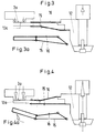
- this distance or the one-sided lifting of the knife edge is avoided by the arrangement of a coupling joint connection between the cutting knives 13 and the hub or the knife head 12.
- the rockers of this coupling joint connection are formed by plate-shaped rockers 15 and 16 which are arranged one above the other and carry the cutting knives 13 and are fastened to the cutter head, as is shown in FIGS. 3 and 3a.
- 3 and 3a show a coupling joint connection in a slightly pretensioned state, so that only a very slight contact of the rotating knife edges 13a with the cutting plate surface 3a takes place. In the case of a support carried out under a stronger force, the knife edge would be lifted off on one side without the coupling joint connection according to the invention, as shown in FIG. 2.
- FIG. 5 shows a coupling joint connection 15 and 16 formed from two plate-shaped rockers which are connected to one another.
Landscapes
- Engineering & Computer Science (AREA)
- Mechanical Engineering (AREA)
- Life Sciences & Earth Sciences (AREA)
- Forests & Forestry (AREA)
- Processing And Handling Of Plastics And Other Materials For Molding In General (AREA)
Applications Claiming Priority (2)
| Application Number | Priority Date | Filing Date | Title |
|---|---|---|---|
| DE4330834 | 1993-09-11 | ||
| DE4330834A DE4330834C1 (de) | 1993-09-11 | 1993-09-11 | Vorrichtung zum Granulieren von Kunststoffen |
Publications (3)
| Publication Number | Publication Date |
|---|---|
| EP0642901A2 true EP0642901A2 (fr) | 1995-03-15 |
| EP0642901A3 EP0642901A3 (fr) | 1995-05-17 |
| EP0642901B1 EP0642901B1 (fr) | 1997-09-24 |
Family
ID=6497445
Family Applications (1)
| Application Number | Title | Priority Date | Filing Date |
|---|---|---|---|
| EP94109683A Expired - Lifetime EP0642901B1 (fr) | 1993-09-11 | 1994-06-23 | Dispositif pour la granulation de matières plastiques |
Country Status (4)
| Country | Link |
|---|---|
| US (1) | US5587186A (fr) |
| EP (1) | EP0642901B1 (fr) |
| JP (1) | JPH07164435A (fr) |
| DE (2) | DE4330834C1 (fr) |
Cited By (1)
| Publication number | Priority date | Publication date | Assignee | Title |
|---|---|---|---|---|
| US4570401A (en) * | 1983-09-20 | 1986-02-18 | Hilti Aktiengesellschaft | Device for adjustably mounting facing plates |
Families Citing this family (13)
| Publication number | Priority date | Publication date | Assignee | Title |
|---|---|---|---|---|
| DE19638994B4 (de) * | 1996-09-23 | 2009-02-26 | Bühler AG | Vorrichtung zum Homogenisieren, Mischen und/oder Granulieren von chemischen Stoffen |
| DE19816611A1 (de) * | 1998-04-15 | 1999-10-21 | Bkg Bruckmann & Kreyenborg Granuliertechnik Gmbh | Granulator zur Herstellung von Pellets aus Kunststoff |
| US6293482B1 (en) | 1998-11-24 | 2001-09-25 | The Japan Steel Works, Ltd. | Method and apparatus for cutting strand |
| JP2002536203A (ja) | 1999-02-04 | 2002-10-29 | ビユーラー・アクチエンゲゼルシヤフト | プラスチック材料の品質を良くするための方法 |
| DE19932303B4 (de) * | 1999-07-10 | 2004-03-18 | Battenfeld Extrusionstechnik Gmbh | Extrusionsvorrichtung zum Extrudieren von Kunststoffmaterial |
| US6604929B2 (en) * | 2000-01-27 | 2003-08-12 | Woodshed Technologies, Inc. | Fiber cutting mechanism |
| AT410072B (de) * | 2001-06-08 | 2003-01-27 | Erema | Verfahren und vorrichtung zur einstellung einer vorspannung der messer einer granuliervorrichtung |
| DE10344793A1 (de) * | 2003-09-26 | 2005-04-14 | Rieter Automatik Gmbh | Vorrichtung zum Granulieren thermoplastischer Kunststoffe |
| US7261546B1 (en) | 2006-05-10 | 2007-08-28 | Owens-Illinois Closure Inc. | Apparatus for severing mold charges in a compression molding machine |
| DE202007014853U1 (de) * | 2007-10-24 | 2008-11-06 | Gala Kunststoff- Und Kautschukmaschinen Gmbh | Granuliervorrichtung sowie Messer- und/oder Schleifkopf für eine solche Granuliervorrichtung |
| JP5235729B2 (ja) * | 2009-03-10 | 2013-07-10 | 株式会社神戸製鋼所 | 樹脂造粒装置 |
| DE102009037398A1 (de) * | 2009-08-13 | 2011-02-17 | Automatik Plastics Machinery Gmbh | Messerkopfhalterung eines Unterwassergranulators |
| JP5572009B2 (ja) * | 2010-06-07 | 2014-08-13 | 株式会社神戸製鋼所 | 水中カット造粒装置用ナイフホルダ |
Family Cites Families (10)
| Publication number | Priority date | Publication date | Assignee | Title |
|---|---|---|---|---|
| US3143766A (en) * | 1961-04-17 | 1964-08-11 | Baker Perkins Inc | Pelletizing apparatus |
| US3271821A (en) * | 1964-07-24 | 1966-09-13 | Frank W Egan & Company | Underwater pelletizer |
| US4021176A (en) * | 1975-10-03 | 1977-05-03 | The Dow Chemical Company | Cutting apparatus |
| US4179255A (en) * | 1978-03-13 | 1979-12-18 | E. I. Du Pont De Nemours And Company | Melt cutter apparatus |
| US4251198A (en) * | 1979-04-27 | 1981-02-17 | Gala Industries, Inc. | Cutter hub with replaceable knife blades for underwater pelletizer |
| DD154935A3 (de) * | 1980-09-23 | 1982-05-05 | Guenter Miklitsch | Messerhalterung fuer einen granulator |
| BR8206444A (pt) * | 1982-11-08 | 1984-06-12 | Pirelli Brasil | Aperfeicoamentos em cabecote granulador |
| IT1180182B (it) * | 1984-06-08 | 1987-09-23 | Montedison Spa | Dispositivo di taglio per la granulazione a caldo di polimeri termoplastici |
| IT1175722B (it) * | 1984-09-13 | 1987-07-15 | Montedison Spa | Dispositivo di taglio per la granulazione a caldo di polimeri termoplastici |
| US5284433A (en) * | 1993-02-25 | 1994-02-08 | E. I. Du Pont De Nemours And Company | Spring-loaded self-adjusting melt cutter |
-
1993
- 1993-09-11 DE DE4330834A patent/DE4330834C1/de not_active Expired - Fee Related
-
1994
- 1994-06-23 EP EP94109683A patent/EP0642901B1/fr not_active Expired - Lifetime
- 1994-06-23 DE DE59404151T patent/DE59404151D1/de not_active Expired - Fee Related
- 1994-09-08 US US08/302,512 patent/US5587186A/en not_active Expired - Fee Related
- 1994-09-09 JP JP6216390A patent/JPH07164435A/ja active Pending
Cited By (1)
| Publication number | Priority date | Publication date | Assignee | Title |
|---|---|---|---|---|
| US4570401A (en) * | 1983-09-20 | 1986-02-18 | Hilti Aktiengesellschaft | Device for adjustably mounting facing plates |
Also Published As
| Publication number | Publication date |
|---|---|
| EP0642901B1 (fr) | 1997-09-24 |
| DE59404151D1 (de) | 1997-10-30 |
| EP0642901A3 (fr) | 1995-05-17 |
| DE4330834C1 (de) | 1994-09-08 |
| JPH07164435A (ja) | 1995-06-27 |
| US5587186A (en) | 1996-12-24 |
Similar Documents
| Publication | Publication Date | Title |
|---|---|---|
| EP0642901B1 (fr) | Dispositif pour la granulation de matières plastiques | |
| DE2718766C3 (de) | Stempel-Abstreifer-Anordnung | |
| DE2926538A1 (de) | Einstellbare halterung fuer den scherstab von futtererntemaschinen | |
| DE1176964B (de) | Revolverstanze | |
| EP2386388B1 (fr) | Dispositif de perforation transversale ou de coupe transversale de bandes de matériaux en bande | |
| EP3406362A1 (fr) | Machine à étirer à chenilles et procédé d'étirage | |
| DE10260110B4 (de) | Vorrichtung zum Stanzen | |
| DE60220033T2 (de) | Vorrichtung und verfahren zur auftrennung der gummierung eines förderbands | |
| DE2114004A1 (de) | Klemmvorrichtung | |
| DE2847353C3 (de) | Maschine zum Abfräsen des Wurzelansatzes von Baumstämmen | |
| EP0694019A1 (fr) | Dispositif pour separer un produit d'une bande defilant en continu | |
| DE102008020248A1 (de) | Schneidemaschine mit vertikalen Antrieb des oberen Vorschubbandes | |
| DE2704246A1 (de) | Pressenkopf mit mehreren stempeln zum wahlweisen abstreifen | |
| DE2810910C2 (de) | Vorrichtung zum Abschneiden von Rohren | |
| WO2020025798A1 (fr) | Système de coupe à double lame | |
| DE3615381C2 (de) | Fuehrungsvorrichtung fuer den messerbalken einer schere zur blechbearbeitung | |
| EP2522477A2 (fr) | Dispositif de profilage de la surface supérieure d'un rail de marchandises en vrac | |
| EP1145654B1 (fr) | Eplucheuse | |
| EP0607914B1 (fr) | Dispositif d'alimentation des pièces à usiner dans une machine automatique pour le travail du bois | |
| EP4349530B1 (fr) | Dispositif de fixation pour une pièce à usiner | |
| DE3308262C1 (de) | Lager für Rollen zum Führen eines Gurtes einer Förderbahn | |
| EP4355510B1 (fr) | Machine de formage dotée d'un dispositif de cisaillement et procédé pour tailler une section de tige | |
| EP0035764B1 (fr) | Cisaille circulaire pour l'usinage de tôles | |
| DE2930415C2 (de) | Vorrichtung zum Andrücken des beweglichen Messers in einer Scheidvorrichtung für Erntemaschinen | |
| DE4111431C2 (de) | Verfahren und Vorrichtung zum Herstellen von endlosen Stahlbändern |
Legal Events
| Date | Code | Title | Description |
|---|---|---|---|
| PUAI | Public reference made under article 153(3) epc to a published international application that has entered the european phase |
Free format text: ORIGINAL CODE: 0009012 |
|
| AK | Designated contracting states |
Kind code of ref document: A2 Designated state(s): DE FR GB IT |
|
| PUAL | Search report despatched |
Free format text: ORIGINAL CODE: 0009013 |
|
| AK | Designated contracting states |
Kind code of ref document: A3 Designated state(s): DE FR GB IT |
|
| 17P | Request for examination filed |
Effective date: 19950428 |
|
| 17Q | First examination report despatched |
Effective date: 19951220 |
|
| GRAG | Despatch of communication of intention to grant |
Free format text: ORIGINAL CODE: EPIDOS AGRA |
|
| GRAH | Despatch of communication of intention to grant a patent |
Free format text: ORIGINAL CODE: EPIDOS IGRA |
|
| ITF | It: translation for a ep patent filed | ||
| GRAH | Despatch of communication of intention to grant a patent |
Free format text: ORIGINAL CODE: EPIDOS IGRA |
|
| GRAA | (expected) grant |
Free format text: ORIGINAL CODE: 0009210 |
|
| AK | Designated contracting states |
Kind code of ref document: B1 Designated state(s): DE FR GB IT |
|
| REF | Corresponds to: |
Ref document number: 59404151 Country of ref document: DE Date of ref document: 19971030 |
|
| ET | Fr: translation filed | ||
| GBT | Gb: translation of ep patent filed (gb section 77(6)(a)/1977) |
Effective date: 19971230 |
|
| PLBE | No opposition filed within time limit |
Free format text: ORIGINAL CODE: 0009261 |
|
| STAA | Information on the status of an ep patent application or granted ep patent |
Free format text: STATUS: NO OPPOSITION FILED WITHIN TIME LIMIT |
|
| 26N | No opposition filed | ||
| PGFP | Annual fee paid to national office [announced via postgrant information from national office to epo] |
Ref country code: GB Payment date: 20010515 Year of fee payment: 8 |
|
| PGFP | Annual fee paid to national office [announced via postgrant information from national office to epo] |
Ref country code: FR Payment date: 20010531 Year of fee payment: 8 |
|
| REG | Reference to a national code |
Ref country code: GB Ref legal event code: IF02 |
|
| PGFP | Annual fee paid to national office [announced via postgrant information from national office to epo] |
Ref country code: DE Payment date: 20020603 Year of fee payment: 9 |
|
| PG25 | Lapsed in a contracting state [announced via postgrant information from national office to epo] |
Ref country code: GB Free format text: LAPSE BECAUSE OF NON-PAYMENT OF DUE FEES Effective date: 20020623 |
|
| GBPC | Gb: european patent ceased through non-payment of renewal fee |
Effective date: 20020623 |
|
| PG25 | Lapsed in a contracting state [announced via postgrant information from national office to epo] |
Ref country code: FR Free format text: LAPSE BECAUSE OF NON-PAYMENT OF DUE FEES Effective date: 20030228 |
|
| REG | Reference to a national code |
Ref country code: FR Ref legal event code: ST |
|
| PG25 | Lapsed in a contracting state [announced via postgrant information from national office to epo] |
Ref country code: DE Free format text: LAPSE BECAUSE OF NON-PAYMENT OF DUE FEES Effective date: 20040101 |
|
| PG25 | Lapsed in a contracting state [announced via postgrant information from national office to epo] |
Ref country code: IT Free format text: LAPSE BECAUSE OF NON-PAYMENT OF DUE FEES Effective date: 20050623 |