EP0642955B1 - Installation de retenue - Google Patents
Installation de retenue Download PDFInfo
- Publication number
- EP0642955B1 EP0642955B1 EP94112623A EP94112623A EP0642955B1 EP 0642955 B1 EP0642955 B1 EP 0642955B1 EP 94112623 A EP94112623 A EP 94112623A EP 94112623 A EP94112623 A EP 94112623A EP 0642955 B1 EP0642955 B1 EP 0642955B1
- Authority
- EP
- European Patent Office
- Prior art keywords
- restraining device
- mesh
- vehicle
- grill
- tensioning
- Prior art date
- Legal status (The legal status is an assumption and is not a legal conclusion. Google has not performed a legal analysis and makes no representation as to the accuracy of the status listed.)
- Expired - Lifetime
Links
- 230000000452 restraining effect Effects 0.000 title claims abstract 20
- 238000004804 winding Methods 0.000 claims description 14
- 229910000831 Steel Inorganic materials 0.000 claims description 4
- 230000007246 mechanism Effects 0.000 claims description 4
- 239000010959 steel Substances 0.000 claims description 4
- 239000012858 resilient material Substances 0.000 claims 1
- 239000000463 material Substances 0.000 description 4
- 239000002184 metal Substances 0.000 description 3
- 208000027418 Wounds and injury Diseases 0.000 description 2
- 238000004873 anchoring Methods 0.000 description 2
- 230000006378 damage Effects 0.000 description 2
- 239000013013 elastic material Substances 0.000 description 2
- 208000014674 injury Diseases 0.000 description 2
- 230000000717 retained effect Effects 0.000 description 2
- 241000282472 Canis lupus familiaris Species 0.000 description 1
- 238000010521 absorption reaction Methods 0.000 description 1
- 230000009471 action Effects 0.000 description 1
- 230000015572 biosynthetic process Effects 0.000 description 1
- 230000008859 change Effects 0.000 description 1
- 210000003746 feather Anatomy 0.000 description 1
- 230000003116 impacting effect Effects 0.000 description 1
- 230000009191 jumping Effects 0.000 description 1
- 230000014759 maintenance of location Effects 0.000 description 1
- 238000004519 manufacturing process Methods 0.000 description 1
- 238000000034 method Methods 0.000 description 1
- 230000002093 peripheral effect Effects 0.000 description 1
- 238000003825 pressing Methods 0.000 description 1
- 230000008569 process Effects 0.000 description 1
- 238000000926 separation method Methods 0.000 description 1
- 239000007787 solid Substances 0.000 description 1
- 230000007704 transition Effects 0.000 description 1
Images





Classifications
-
- B—PERFORMING OPERATIONS; TRANSPORTING
- B60—VEHICLES IN GENERAL
- B60R—VEHICLES, VEHICLE FITTINGS, OR VEHICLE PARTS, NOT OTHERWISE PROVIDED FOR
- B60R21/00—Arrangements or fittings on vehicles for protecting or preventing injuries to occupants or pedestrians in case of accidents or other traffic risks
- B60R21/02—Occupant safety arrangements or fittings, e.g. crash pads
- B60R21/06—Safety nets, transparent sheets, curtains, or the like, e.g. between occupants and glass
-
- B—PERFORMING OPERATIONS; TRANSPORTING
- B60—VEHICLES IN GENERAL
- B60R—VEHICLES, VEHICLE FITTINGS, OR VEHICLE PARTS, NOT OTHERWISE PROVIDED FOR
- B60R21/00—Arrangements or fittings on vehicles for protecting or preventing injuries to occupants or pedestrians in case of accidents or other traffic risks
- B60R21/02—Occupant safety arrangements or fittings, e.g. crash pads
- B60R21/06—Safety nets, transparent sheets, curtains, or the like, e.g. between occupants and glass
- B60R2021/065—Safety nets, transparent sheets, curtains, or the like, e.g. between occupants and glass comprising energy absorbing mounting means
Definitions
- the present invention relates to a restraint device for objects loosely stowed in a vehicle, consisting of a grille or net element which defines a restraint surface, as well as fastening devices for this net or grille element on the vehicle, wherein a tensile stress, at least partially by the Fastening devices guided, flexible and essentially linear clamping element and a tension device are provided.
- Such a device is known for example from patent application GB-A-2 111 439.
- the net is provided on three of its four peripheral side edges with an essentially non-stretchable rope which is held at the corners of the net by elastic loops.
- the length of this rope is adjustable on one side.
- the fourth side edge is formed by an elastically stretchable rope, at the ends of which fastening devices, such as hooks, are provided.
- the tension in the circumferential non-elastic rope and in the elastic rope is generated essentially by the fact that the same is tensioned when the elastic rope is fastened must become.
- the elastic tensioning elements or eyes on the netting corners formed by the inextensible rope also provide part of the tensioning force.
- This device corresponds essentially to other known restraint devices with nets which are approximately adapted in their outer shape to the inner cross section of a motor vehicle and which are attached with their outer edge to hooks attached to bars, roof and other bodywork or built-in parts and thus, for example, a rear one Separate the space of the vehicle from the front space.
- nets are often found on so-called combination vehicles, in which the rear luggage compartment above the rear seat back is separated by such a netting.
- such nets are at best suitable for pets, such as To prevent dogs from jumping onto the seats from the rear luggage compartment, or to prevent loose goods from slipping or falling over the back of the back seat onto the back seat in normal operating conditions.
- the present invention has for its object to provide a restraint device with the features mentioned above, which is easy to assemble and disassemble, easy to use and also stowable on the one hand and on the other hand less flexibility and the known, flexible networks offers significantly improved safety, especially in the event of an accident.
- brackets for the network or grid element are attached to the tensioning element, the tensioning in the tensioning device with the aid of the tensioning device Clamping element can be increased to a desired value or, for example for dismantling purposes, reduced.
- the net is not simply hooked into its hook with its outer edge or an outer, circumferential border, but it is fastened to a linear tensioning element via special brackets, which in turn is guided on or through the fastening devices and which after attachment to the fastening devices can still be tensioned later, so that the tightness of the tensioning element and also the net or lattice work, which is attached to the tensioning element via the net holders, makes the entire restraint device much tighter and more unrelenting and also objects flying through the vehicle in the event of an accident holds back safely and without risk of injury to the vehicle occupants.
- the subsequent tensioning which is still possible with the aid of a tensioning device according to the present invention even after anchoring the net and / or the tension element at the fastening points, also allows the application of much higher tensile stresses, so that a net or grid structure is also involved can get a much firmer structure.
- the net material itself can be made firmer, stiffer and less flexible, since it no longer has to be brought into its final fastening position by hand. Nevertheless, the net or grille can be made sufficiently flexible to be easily dismantled and stowed away.
- the tension element can be moved in the longitudinal direction to the net holders.
- a larger section of the tension element can, if necessary, also be moved along the net brackets, for example in order to be accommodated in a tension device, whereby the tension in the tension element increases without the position of the net and the net brackets having to change .
- the lattice-like or mesh-like element which is the collecting surface, is not intended to be restrictive forms for objects, addressed only as a ⁇ network '', it being understood that such a network can also have grid-like rigid surfaces or sections.
- the net holders furthermore have tubular guide openings, in which the tension element is received and in which it can slide in the longitudinal direction.
- a winding device with a ratchet mechanism is provided as the tension device.
- One of the ends of the tensioning element can be fixed in the vicinity of the winding device, while the other is wound onto this winding device, e.g. on a winding drum and with the help of a crank, a ratchet mechanism preventing the loosening and turning backwards of the winding drum.
- the ratchet mechanism in question can also be disengaged in order, if necessary, to be able to reduce the tension in the tensioning element again, for example when dismantling the restraint device.
- the tension element runs at least predominantly along the outer contours of the network or network element.
- the latter is generally shaped in such a way that, at least in the state spanned by the tension element, it covers the free cross section of a vehicle, e.g. above the backrest of a caravan or station wagon, possibly with the exception of edge areas and curves that are difficult to access.
- the tension element then also runs along this outer contour and forms, so to speak, a tensioning frame for the net, the strength and rigidity of which is improved by increasing the tension.
- the tension element or the outer contour of the network has a substantially trapezoidal shape, the shorter of the parallel sides of this trapezoid generally running along the vehicle roof, the obliquely inclined side edges running parallel to the windows or window bars and the longer of the parallel sides runs parallel to the floor, either near the floor or near the top edge of a rear seat backrest.
- a configuration e.g. four attachment points on the vertical bars on both sides of the vehicle, which define the corner points of such a trapezoid.
- the tension element is a band or rope made of a rubber-elastic material with high tensile strength and preferably a large modulus of elasticity, e.g. B. a corresponding plastic material.
- the tension element however, it can also be a steel rope or band.
- the fastening devices at the fastening points are typically rigid elements with guide eyes or guide rollers for the tension element.
- the fastening devices can also be multi-part parts, one of the elements being fixedly attached to a vehicle spar or another part of the vehicle rigidly connected to the body, while the other element is e.g. can simply be a guide eye.
- the fastening devices have plastically deformable absorbing elements for absorbing load peaks in accident situations. This can prevent the occurrence of load peaks, for example if a 10 kg heavy or even heavier object is caught by the network in a rear-end collision, the network or the tension element tearing, so that instead the absorbing elements give way a bit and thus the course smoothen the load curve a little, even if it allows the object to move a little further into the front compartment of the vehicle.
- fastening devices can be removed, but can be locked on parts rigidly connected to the vehicle body. You can then remove the fasteners when disassembling the network, which would otherwise potentially interfere.
- the tension element preferably consists of one piece and runs in a more or less closed path at least partially in the vicinity of the outer contour of the net or grid to be tensioned.
- the winding device mentioned above as a tension device, it is also possible to increase the tension in the tension element by forcibly guiding it along a detour.
- a detour in which the lower edge of the network, along which the tension element runs, is at a distance from the floor of the vehicle, for example anchoring devices can be provided on the floor and one or more U are then used with the aid of suitable tension elements -shaped loops of the tension element pulled down towards the bottom. Outside of these U-shaped loops, however, the mesh brackets should then have rigid, horizontal guides in the area of this lower edge. A significant part of the tension is also from the net itself, so that it is held very tight and not very flexible in its overall position.
- FIG. 1 shows a net 1, mounted on the bars 6 of a vehicle with the aid of fastening devices 4 and the tensioning element 3 and the tensioning device 2.
- the fastening devices 4 for example, are each rigid on the body or on the bars 6 of the vehicle secured bracket with a guide eye, a rope-shaped tensioning element 3, starting from the tensioning device 2, running through all four eyes and back to the tensioning device 2.
- the clamping element 3 spans a trapezoidal frame, the corner points of which Eyelets of the mounting bracket 4 are defined. Between two adjacent fastening brackets 4, the cable 3 runs through mesh brackets 5.
- These can be, for example, tubular guides through which the cable 3 runs in the longitudinal direction and to which one side edge of the mesh 1 is firmly attached at the same time.
- the corresponding net holder 5 is divided in order to be able to accommodate the tensioning device 2 in the middle. It is understood that at the beginning, if, for example, the rope 3 is not yet tensioned and hangs very loosely, you can easily hang the rope 3 at its exposed areas between the net brackets 5 in the eyelets of the mounting bracket 4, provided that these eyelets are accessible in any way, for example have a labyrinth or meander feed or are in the form of carabiner hooks or the like, so that the rope does not have to be threaded.
- the rope can then be so loose, for example, that it extends from the net 1 in the form of a U-shaped loop to the respective mounting bracket 4.
- these loops are eliminated by now tightening the rope 3 with the aid of the tensioning device 2, so that finally the state shown in FIG. 1 is established.
- the mesh brackets 5 are essentially rigid elements, since then the mesh is tightened even more across the entire surface.
- FIG. 2 shows details of the tensioning device 2.
- a winding shaft 12 can be seen, which can be rotated in the direction of the arrow indicated on the crank with a crank 13 attached to the axis 11.
- the end 17 of the rope 3 is wound onto the winding shaft 12.
- an asymmetrically toothed ratchet wheel 14 can be seen, which is in engagement with a pivotably mounted pawl 15.
- the pawl 15 is resiliently biased in the direction of engagement with the ratchet wheel 14.
- the pawl 15 is designed as a double-armed lever, the second end 18 of which protrudes from the housing 10. In this way, it is possible to bring the pawl 15 out of engagement with the teeth of the ratchet wheel 14 by pressure on the lever end 18, so that the Winding shaft 12 is freely rotatable in the reverse direction.
- the lever 18 is actuated, however, the handle of the crank 13 is initially held so that the unwinding takes place in a controlled manner.
- FIG. 2 is purely schematic and that the specific embodiment, in particular with regard to the scale ratios and dimensions, can differ significantly from this.
- the second end 16 of the rope 3 is attached from the other side of the tensioning device 2 by means of a clamping device 9, which is also only indicated schematically here.
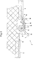
- FIG. 3 shows an embodiment in which the fastening device 4 consists of a solid, rigid material, preferably a steel strip, and generally remains permanently connected to the cable or tensioning element 3, so that the fastening strips 4 are attached to corresponding devices for assembly and disassembly 21 is fixed in the vehicle.
- the metal strip 4 initially has an eyelet 19 through which the rope 3 is guided, wherein a guide roller could easily be arranged in the eyelet 19 in order to facilitate the movement of the rope 3 through the eyelet 19, in particular during tensioning.
- the other end 20 of the strip 4 is T-shaped in such a way that it fits into a recess 21 which is introduced into a vehicle spar 6 or into a part fastened to the spar 6.
- the illustration in FIG. 3 is again only very schematic, without showing the exact function of the connection of the parts 20, 21, but this type of connection is generally known in the prior art and therefore requires no further explanation.
- a resiliently biased securing element 8 also ensures that after the elements 20, 21 are brought into engagement with one another, they cannot disengage by themselves. After, for example, the T-shaped part 20 has been inserted appropriately into the recess 21, the initially retained part 8 slides over the connection point under the action of the resilient bias, engaging behind the spar 6 or with a second, U-shaped bent end the like and prevents the part 20 from being moved out of the recess 21 by covering the connection point.
- the metal strip 4 has been slit in the longitudinal direction and has been swaged into an eyelet 7 in the slotted area.
- This section thus has the function of an absorption element for peak loads. It will be an excessively large one If tension is exerted on the cable 3 and thus also on the fastening strip 4, the element 4 begins to stretch when a limit value that can be predetermined by the design of the absorbing element 7 begins to stretch, the eyelet 7 gradually tapering again in the direction of the original slot.
- Figure 4 shows an enlarged perspective view schematically of a net holder 5.
- the net holder 5 then consists of a U-shaped folded strip, e.g. made of plastic material, one edge of the net 1 being clamped between the two legs 24 of this U-shaped strip. In this area the legs 24 are then pressed together and fastened together, e.g. welded to one another, a firm connection between the net 1 and the net holder 5 being produced.
- the cable 3 runs through a recess 23 and can be moved in the longitudinal direction through the recess 23. This can be ensured, for example, by providing appropriate grooves or grooves before the strip 22 is folded together in a U-shape.
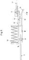
- the tensioning device here essentially consists of two parts 10 ', 12' which are movable relative to one another and resiliently preloaded against one another. Each of the parts 10 ', 12' is firmly connected to one end 16 or 17 of the rope 3.
- the parts 10 ', 12' are approximately L-shaped, one of their L-legs being aligned parallel to that of the other, so that a spring 13 'can be received between the two L-legs extending perpendicularly thereto.
- holding and guide elements are also provided, which are not shown in FIG. 5 and which prevent the parts 10 ', 12' from tilting or slipping apart.
- one of the parallel L-legs is provided with toothing 14 ', while the other, parallel L-leg is extended beyond the cross leg to the toothing by a spring clip 15' which has an engagement tooth 19 '.
- the spring clip 15 ' can be disengaged by hand by pressing in the direction of the arrow 18', in which case the spring 13 ensures a minimum tension in the cable 3.
- the adjustment path is limited to the length of the toothing 14 ', which can, however, be significantly larger than indicated in the merely schematic FIG. 5.
- a tensioning device could be suitable for sufficiently tensioning a steel cable 3, for example.
- FIG. 6 shows a variant of the invention in which the rope 3 is forcibly guided along a U-shaped detour to increase the tensile stress.
- the vehicle body or the spars 6 can again be seen with four strip-shaped fastening devices 4, which span the rope 3 and thus also the net 1 in a trapezoidal manner.
- mounting brackets 34, 35 with at least one tensioning device 27 can be seen on the floor 36 of the vehicle, which is only shown on the left between the cable 3 and the mounting bracket 35 in the example of FIG. 6, but also in a similar manner between the mounting bracket 34 and the cable 3 can be provided.
- the tensioning device 27 on the left mounting bracket 35 is used.
- the lower net holder 31 has two recesses 28, 29, along which the tubular guide 23 in the net holder 5, as shown, for example, in FIG. 4, is interrupted to the outside, so that the cable 3 is gripped in this area and to the outside Formation of the U-shaped loops can be pulled away.
- the lower net holder 31 can, even if this is not shown in FIG. 6, be provided continuously until shortly before the lower corner points of the spanned trapezoid.
- FIG. 7 also shows an alternative variant of a net holder with a guide tube 23 'encompassed by the legs of the strip 22 which are folded together in a U-shape.
- this embodiment corresponds essentially to the configuration already described in connection with FIG. 4.
- Figure 8 shows a further variant of a net holder, which essentially consists of a guide tube 23 '', which is woven or inserted into the outer mesh of the net edge and in such a way that the adjacent stitches of the outer stitch row of the net 1 pass alternately from different sides .
- FIG. 9 shows a tensioning device as it could be used, for example, as a tensioning device 27 in the embodiment according to FIG. 6 and which is very similar to the variant described in connection with FIG. 5, with the exception of the fact that the two ends 16, 17 of the rope are not included the elements 10 '' and 12 '' are connected, but that one end 33 of the leg of the element 10 '' hook-shaped grips the loop formed by the rope 3, while the hook-shaped end of the part 12 '' anchored to the floor 36 of the vehicle Fastening bracket 35 encompasses. Otherwise, the parts provided with the same reference numbers as in FIG. 5, but with additional two dashes, correspond exactly to the parts described in connection with FIG. 5.
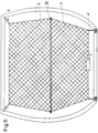
- FIG. 10 again shows a variant very similar to that of FIG. 6, but the two middle fastening strips 4 on the right and left on the spars 6 have been dispensed with, while the lower mounting element 31 in this variant in any case continuously between the right and left ends 38 , 39 is formed and is also made as stiff as possible in order to maintain the trapezoidal shape of the network.
- the production of the U-shaped loops of the rope 3 again corresponds exactly to the process described in connection with FIG. 6.
- one leg of the U-shaped loops of the rope 3 leads up to one of the upper fastening strips 4 and does not run along the outer contour of the net 1, while the second leg follows the U-shaped loops of the rope 3 ends as before on the lower support element 31 'and thus also ensures the exertion of a tensioning force on the net 1 as a whole.
- the width of the interior space between the floor and the roof can vary considerably, which could lead to the fact that a net attached in the corner transitions floor / side wall or roof / side wall leaves considerable gaps between the side wall and the net edge.
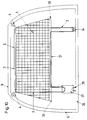
- An embodiment such as that shown in FIG. 11 is intended for such applications.
- two spaced apart, in this case opposite, sections of the tensioning element are held apart by a stiffening element 26.
- any sections of the tensioning element which are spaced apart from one another and do not run along the same straight line can be held apart by such stiffening elements 26.
- the course of the net edge can be adapted to the contours of a vehicle interior with sufficient accuracy so that the remaining gaps between the net edge and the side wall or between the net edge and the roof or floor of the vehicle do not exceed a certain, predeterminable maximum dimension.
- the tube 31 with the end sections 38, 39 represents a corresponding stiffening element, which in this case is not between opposite sections of the tensioning element, but up to opposite edges of the network extends.
- the restraint device according to the invention combines the simple assembly and stowage options of the known, simple network separations with the high retention capacity of a rigid device, which, however, could only be assembled with great difficulty according to the prior art.
Landscapes
- Engineering & Computer Science (AREA)
- Mechanical Engineering (AREA)
- Emergency Lowering Means (AREA)
- Superstructure Of Vehicle (AREA)
- Materials For Medical Uses (AREA)
- Body Structure For Vehicles (AREA)
- Fittings On The Vehicle Exterior For Carrying Loads, And Devices For Holding Or Mounting Articles (AREA)
Claims (15)
- Système de retenue pour des objets logés d'une manière lâche dans un véhicule, constitué d'un élément (1), en forme de grille ou de filet, définissant une surface de retenue, et de dispositifs de fixation (4), disposés contre le véhicule et destinés à l'élément (1) en forme de grille ou de filet, où on prévoit un élément de serrage (3), pouvant être exposé à une contrainte de traction, guidé au moins partiellement à travers les dispositifs de fixation (4), souples et essentiellement linéaires, ainsi qu'un dispositif (2) pour appliquer une contrainte de traction, caractérisé en ce que des attaches (5) destinées à l'élément en forme de grille ou de filet (1) sont rapportées à l'élément de serrage (3), la contrainte de traction dans l'élément de serrage (3) pouvant, à l'aide du dispositif (2) destiné à appliquer une contrainte de traction, être augmentée à une valeur voulue, ou encore diminuée, par exemple pour permettre un démontage.
- Système de retenue selon la revendication 1, caractérisé en ce que l'élément de serrage (3) est mobile dans la direction longitudinale par rapport aux attaches (5) destinées au filet.
- Système de retenue selon la revendication 2, caractérisé en ce que les attaches (5) destinées au filet comportent des ouvertures de guidage tubulaires (23) pour l'élément de serrage (3).
- Système de retenue selon l'une des revendications 1 à 3, caractérisé en ce que le dispositif (2) destiné à appliquer une contrainte de traction comporte un dispositif d'enroulement (11, 12, 13) comportant un mécanisme à cliquets (14, 15).
- Système de retenue selon l'une des revendications 1 à 4, caractérisé en ce que l'élément de serrage court au moins dans sa majorité le long des contours extérieurs de l'élément (1) en forme de grille ou de filet.
- Système de retenue selon l'une des revendications 1 à 5, caractérisé en ce que les contours extérieurs de l'élément (1) en forme de grille ou de filet sont trapézoïdaux.
- Système de retenue selon l'une des revendications 1 à 6, caractérisé en ce que l'élément de serrage est un câble en un matériau ayant l'élasticité du caoutchouc.
- Système de retenue selon l'une des revendications 1 à 6, caractérisé en ce que l'élément de serrage est un câble ou une bande en acier.
- Système de retenue selon l'une des revendications 1 à 8, caractérisé en ce que les dispositifs de fixation (4) sont pour l'essentiel des éléments rigides comportant des oeillets (19) ou des galets de guidage pour l'élément de serrage (3).
- Système de retenue selon l'une des revendications 1 à 9, caractérisé en ce que les dispositifs de fixation (4) présentent des éléments absorbants (7), pouvant subir une déformation plastique, pour absorber les pointes de charge.
- Système de retenue selon l'une des revendications 1 à 10, caractérisé en ce que les dispositifs de fixation sont verrouillables contre des pièces (21), liées d'une manière rigide à la carrosserie du véhicule.
- Système de retenue selon l'une des revendications 1 à 11, caractérisé en ce que l'élément de serrage (3) est constitué d'une pièce monobloc, courant au voisinage du bord extérieur de l'élément en forme de grille ou de filet.
- Système de retenue selon l'une des revendications 1 à 12, caractérisé en ce que le dispositif (2) destiné à appliquer une contrainte de traction représente un guidage en déviation (35, 27, 28, 31) pour l'élément de serrage (3).
- Système de retenue selon la revendication 13, caractérisé en ce que l'arête inférieure de l'élément (11) en forme de grille ou de filet se trouve à une certaine distance du plancher du véhicule, et que l'on prévoit des dispositifs de serrage (35, 27) par lesquels l'élément de serrage (3) est tiré sous forme d'une boucle en U, à partir de I'arête inférieure du filet, dans la direction du plancher du véhicule.
- Système de retenue selon l'une des revendications 1 à 14, caractérisé en ce qu'il comporte au moins un élément de rigidification (26), qui s'étend entre des segments, situés à une certaine distance les uns des autres et ne courant pas le long de la même ligne droite, de l'élément de serrage (3) et/ou du bord de l'élément (1) en forme de grille ou de filet, et maintient ces segments à la distance prédéfinie par l'élément de rigidification (26).
Applications Claiming Priority (2)
| Application Number | Priority Date | Filing Date | Title |
|---|---|---|---|
| DE4331278A DE4331278A1 (de) | 1993-09-15 | 1993-09-15 | Rückhaltevorrichtung |
| DE4331278 | 1993-09-15 |
Publications (2)
| Publication Number | Publication Date |
|---|---|
| EP0642955A1 EP0642955A1 (fr) | 1995-03-15 |
| EP0642955B1 true EP0642955B1 (fr) | 1997-12-17 |
Family
ID=6497751
Family Applications (1)
| Application Number | Title | Priority Date | Filing Date |
|---|---|---|---|
| EP94112623A Expired - Lifetime EP0642955B1 (fr) | 1993-09-15 | 1994-08-12 | Installation de retenue |
Country Status (4)
| Country | Link |
|---|---|
| EP (1) | EP0642955B1 (fr) |
| AT (1) | ATE161232T1 (fr) |
| DE (2) | DE4331278A1 (fr) |
| ES (1) | ES2110668T3 (fr) |
Cited By (4)
| Publication number | Priority date | Publication date | Assignee | Title |
|---|---|---|---|---|
| EP1188621A2 (fr) | 2000-09-15 | 2002-03-20 | PETER BUTZ GmbH & Co Verwaltungs-KG | Dispositif de fixation d'une extrémité d'un système de sécurité dans un véhicule et mise sous tension de celle-ci |
| DE10341411B3 (de) * | 2003-09-05 | 2005-03-24 | Johnson Controls Gmbh | Deformierbare Halterung zur Befestigung eines Sicherheitstrennnetzes im Laderaum eines Kraftfahrzeugs |
| EP0995641B2 (fr) † | 1998-10-20 | 2010-03-03 | Centre D'etudes Et Recherche Pour L'automobile ( Cera) | Dispositif de protection tel que filet de protection pour vehicule automobile |
| EP4371824A1 (fr) * | 2022-11-18 | 2024-05-22 | Volkswagen Aktiengesellschaft | Dispositif de séparation d'espace et véhicule automobile |
Families Citing this family (31)
| Publication number | Priority date | Publication date | Assignee | Title |
|---|---|---|---|---|
| DE19531303C1 (de) * | 1995-08-25 | 1997-02-06 | Baumeister & Ostler Gmbh Co | Laderaumabtrennung zwischen einem Fondraum und einem Laderaum eines Innenraumes eines Kombi-Personenkraftwagens |
| DE19531304B4 (de) * | 1995-08-25 | 2007-02-01 | Bos Gmbh & Co. Kg | Sicherungsnetz zum Überspannen und Festlegen von Ladegut auf einem Laderaumboden eines Kraftfahrzeugs |
| ES2119539T3 (es) * | 1995-10-11 | 1998-10-01 | Butz Peter Verwaltung | Dispositivo de retencion como, por ejemplo, una red de retencion para los vehiculos automoviles. |
| US5772370A (en) | 1995-11-22 | 1998-06-30 | Moore; Donal | Retractable and/or removable net type cargo restraining system |
| US6817644B2 (en) | 1995-11-22 | 2004-11-16 | Exco Automotive Solutions, L.P. | Load retaining barrier net for motor vehicle |
| GB2321436B (en) | 1997-01-24 | 2000-12-20 | Autoliv Dev | Improvements in or relating to a safety device in a motor vehicle |
| DE19718364C1 (de) * | 1997-05-02 | 1998-08-06 | Butz Peter Verwaltung | Rückhalte- bzw. Trennvorrichtung für Kraftwagen |
| DE19729660C1 (de) * | 1997-07-11 | 1998-08-27 | Butz Peter Verwaltung | Rückhalte- bzw. Trennvorrichtung für Kraftwagen, mit einer Rückhaltebahn |
| DE19730801C1 (de) * | 1997-07-18 | 1999-03-25 | Baumeister & Ostler Gmbh Co | Einfaches Sicherheitsnetz mit Haken zum Einhängen |
| JP2000002843A (ja) * | 1998-06-16 | 2000-01-07 | Seiko Giken:Kk | 2×2光ファイバスイッチ |
| DE29812708U1 (de) * | 1998-07-16 | 1998-11-12 | Trw Repa Gmbh | Rückhaltemodul für ein Kraftfahrzeug |
| DE19835230B4 (de) * | 1998-08-04 | 2004-02-19 | Baumeister & Ostler Gmbh & Co | Einfaches Rückhaltenetz mit unnachgiebigen Haltebändern |
| DE29918825U1 (de) * | 1998-10-15 | 2000-03-30 | Peter Butz Gmbh & Co Verwaltungs-Kg, 40764 Langenfeld | Trenn- und/oder Rückhaltevorrichtung für Fahrzeuge, wie für Kombinationskraftwagen oder dgl. |
| EP0997351B1 (fr) | 1998-10-15 | 2003-01-22 | PETER BUTZ GmbH & Co Verwaltungs-KG | Dispositif de séparation et/ou de rétention pour véhicules, comme des véhicules motorisés type break ou pareils |
| FR2784632B1 (fr) * | 1998-10-20 | 2000-12-29 | Cera | Dispositif de protection tel que filet de protection pour vehicule automobile |
| DE19906050A1 (de) * | 1999-02-12 | 2000-08-17 | Volkswagen Ag | Anordnung zur Befestigung eines Bauteils an einer Halterung |
| DE60017403T2 (de) * | 1999-07-08 | 2005-12-29 | Exco Automotive Solutions, L.P., Troy | Sperrnetz für kraftfahrzeuge |
| AU2002361612A1 (en) * | 2001-11-12 | 2003-05-26 | Polytech Netting, L.P. | Frameless load restraining vehicular barrier device |
| DE60206247T2 (de) * | 2002-04-19 | 2006-06-29 | Ford Global Technologies, LLC (n.d.Ges.d. Staates Delaware), Dearborn | Befestigungshaken für ein Sicherheitsnetz eines Kraftfahrzeuges |
| DE102004050546B4 (de) * | 2004-10-16 | 2022-02-24 | Bayerische Motoren Werke Aktiengesellschaft | Rückhalteeinrichtung für Gepäckstücke in einem Fahrzeug |
| DE102006051477A1 (de) * | 2006-10-31 | 2008-05-15 | Hs Genion Gmbh | Vorrichtung zum Abtrennen eines Ladebereichs in einem Kraftfahrzeug |
| DE102007055471A1 (de) * | 2007-11-14 | 2009-05-20 | Bos Gmbh & Co. Kg | Rolloeinrichtung für ein Kraftfahrzeug |
| DE102009024453A1 (de) * | 2009-06-10 | 2010-12-16 | Bayerische Motoren Werke Aktiengesellschaft | Kraftfahrzeug mit einem U-förmigen Bügel |
| US9016759B2 (en) * | 2013-01-25 | 2015-04-28 | Honda Motor Co., Ltd. | Vehicle including net structure |
| FR3008365B1 (fr) * | 2013-07-10 | 2016-12-09 | Centre D'etude Et De Rech Pour L'automobile (Cera) | Dispositif de protection separant un compartiment a bagages d'un habitacle de vehicule automobile |
| FR3084627B1 (fr) * | 2018-08-06 | 2020-09-11 | Renault Sas | Dispositif d'accrochage d'un filet de retenue de charges dans un vehicule automobile |
| CN113635838B (zh) * | 2020-05-11 | 2025-04-01 | 昆山皇田汽车配件工业有限公司 | 遮物帘 |
| SE2250115A1 (en) * | 2022-02-04 | 2023-08-05 | Klippan Safety Ab | Barrier net |
| CN115303202B (zh) * | 2022-08-15 | 2024-10-29 | 重庆长安汽车股份有限公司 | 一种汽车车内帘布隔断装置 |
| EP4410605A1 (fr) * | 2023-02-01 | 2024-08-07 | Klippan Safety AB | Filet de barrière pliable |
| DE102023110673A1 (de) * | 2023-04-26 | 2024-10-31 | Bayerische Motoren Werke Aktiengesellschaft | Trennanordnung und Kraftfahrzeug mit derartiger Trennanordnung |
Family Cites Families (9)
| Publication number | Priority date | Publication date | Assignee | Title |
|---|---|---|---|---|
| US3525535A (en) * | 1967-02-18 | 1970-08-25 | Gic Kk | Safety device for vehicle passengers |
| DE2050331A1 (de) * | 1970-10-14 | 1972-04-20 | Wirth geb. Weichselgärtner, Hannelore, 4154 Tönisvorst | Sicherheitsvorrichtung zum Auffangen von Personen und Gegenständen innerhalb von Fahrzeugen zum Schutz vor Unfallstößen |
| DE2418145A1 (de) * | 1974-04-13 | 1975-10-30 | Volkswagenwerk Ag | Sicherheitseinrichtung |
| DE7611939U1 (de) * | 1976-04-15 | 1976-08-19 | 2000 Hamburg | Trenn-Netz für Pkw und Kombifahrzeuge |
| DE2749560A1 (de) * | 1977-11-05 | 1979-05-10 | Eugen Seitz | Vorrichtung zum abteilen des hinteren laderaumes vom fahrgastraum eines fuer den transport von personen und lasten ausgelegten kraftfahrzeuges (kombifahrzeug) |
| FR2438562A2 (fr) * | 1978-10-10 | 1980-05-09 | Vandamme Ets Georges | Perfectionnements a un dispositif notamment destine au compartimentage transversal d'une automobile |
| GB2111439B (en) * | 1981-12-18 | 1985-06-12 | Georges Vandammel Etablissemen | Device for the transverse partitioning of a motor vehicle |
| FR2562007B1 (fr) * | 1984-03-28 | 1988-06-17 | Vandamme Georges | Dispositif destine au compartimentage transversal d'une voiture automobile |
| DE4010209C2 (de) * | 1990-03-30 | 1994-03-10 | Baumeister & Ostler Gmbh Co | Sicherheitsnetz |
-
1993
- 1993-09-15 DE DE4331278A patent/DE4331278A1/de not_active Ceased
-
1994
- 1994-08-12 AT AT94112623T patent/ATE161232T1/de not_active IP Right Cessation
- 1994-08-12 EP EP94112623A patent/EP0642955B1/fr not_active Expired - Lifetime
- 1994-08-12 ES ES94112623T patent/ES2110668T3/es not_active Expired - Lifetime
- 1994-08-12 DE DE59404813T patent/DE59404813D1/de not_active Expired - Fee Related
Cited By (7)
| Publication number | Priority date | Publication date | Assignee | Title |
|---|---|---|---|---|
| EP0995641B2 (fr) † | 1998-10-20 | 2010-03-03 | Centre D'etudes Et Recherche Pour L'automobile ( Cera) | Dispositif de protection tel que filet de protection pour vehicule automobile |
| EP1188621A2 (fr) | 2000-09-15 | 2002-03-20 | PETER BUTZ GmbH & Co Verwaltungs-KG | Dispositif de fixation d'une extrémité d'un système de sécurité dans un véhicule et mise sous tension de celle-ci |
| DE10046142A1 (de) * | 2000-09-15 | 2002-04-04 | Butz Peter Verwaltung | Vorrichtung zur Festlegung eines Endbereiches einer Fahrzeug- Sicherheitseinrichtung an einem fahrzeugseitigen Befestigungspunkt sowie zur Spannung des Endbereichs der Fahrzeug-Sicherheitseinrichtung relativ zu dem Befestigungspunkt |
| DE10046142B4 (de) * | 2000-09-15 | 2006-08-24 | Bos Gmbh & Co. Kg | Vorrichtung zur Festlegung eines Endbereiches einer Fahrzeug- Sicherheitseinrichtung an einem fahrzeugseitigen Befestigungspunkt sowie zur Spannung des Endbereichs der Fahrzeug-Sicherheitseinrichtung relativ zu dem Befestigungspunkt |
| DE10341411B3 (de) * | 2003-09-05 | 2005-03-24 | Johnson Controls Gmbh | Deformierbare Halterung zur Befestigung eines Sicherheitstrennnetzes im Laderaum eines Kraftfahrzeugs |
| WO2005028262A1 (fr) | 2003-09-05 | 2005-03-31 | Johnson Controls Gmbh | Fixation deformable, destinee notamment a un filet de separation pour l'espace de chargement d'un vehicule automobile |
| EP4371824A1 (fr) * | 2022-11-18 | 2024-05-22 | Volkswagen Aktiengesellschaft | Dispositif de séparation d'espace et véhicule automobile |
Also Published As
| Publication number | Publication date |
|---|---|
| ATE161232T1 (de) | 1998-01-15 |
| DE59404813D1 (de) | 1998-01-29 |
| ES2110668T3 (es) | 1998-02-16 |
| EP0642955A1 (fr) | 1995-03-15 |
| DE4331278A1 (de) | 1995-03-16 |
Similar Documents
| Publication | Publication Date | Title |
|---|---|---|
| EP0642955A1 (fr) | Installation de retenue | |
| DE102007046958A1 (de) | Energieabsorptions-Sitzverankerungs-Rückhaltesystem für Kinder-Sicherheitssitze | |
| DE102010051325A1 (de) | Sitzfuß für einen Personensitz | |
| DE19546646A1 (de) | Rückenlehne für Kraftfahrzeugsitze | |
| WO2000007852A2 (fr) | Filet de retenue simple muni de bandes de retenue | |
| DE7500822U (de) | Veränderliche, demontierbare Laderaumabdeckung für Kraftfahrzeuge | |
| DE60017403T2 (de) | Sperrnetz für kraftfahrzeuge | |
| DE19730801C1 (de) | Einfaches Sicherheitsnetz mit Haken zum Einhängen | |
| EP0586842B1 (fr) | Aide à l'arrimage pour l'intérieur d'un véhicule | |
| DE69725164T2 (de) | Lasthaltesystem und verfahren zum halten von lasten | |
| DE102019118107A1 (de) | Transportwagen für Stückgut | |
| DE102015108782A1 (de) | Fahrzeugaufbau, insbesondere für Nutzfahrzeuge, Nutzfahrzeug mit einem solchen Fahrzeugaufbau und Herstellungsverfahren | |
| DE60206247T2 (de) | Befestigungshaken für ein Sicherheitsnetz eines Kraftfahrzeuges | |
| DE69924444T2 (de) | Schutzvorrichtung insbesondere Sicherheitsnetz für Kraftfahrzeuge | |
| DE102007022477A1 (de) | Laderaumsystem | |
| EP3366511B1 (fr) | Ancrage ceinture pour un siège de véhicule ou une banquette de véhicule | |
| DE19836849C1 (de) | Dachanordnung | |
| DE102011122189B4 (de) | Windschott | |
| DE2656249A1 (de) | Aufprallschutzvorrichtung fuer die insassen von fahrzeugen, insbesondere von personenkraftfahrzeugen | |
| DE10046142B4 (de) | Vorrichtung zur Festlegung eines Endbereiches einer Fahrzeug- Sicherheitseinrichtung an einem fahrzeugseitigen Befestigungspunkt sowie zur Spannung des Endbereichs der Fahrzeug-Sicherheitseinrichtung relativ zu dem Befestigungspunkt | |
| DE10341852B4 (de) | Aufrolleinrichtung, insbesondere ein Fangnetz- oder Abdeckrollo, zur Anordnung in einem Kraftfahrzeug | |
| EP2321151A1 (fr) | Dispositif de transport | |
| DE102004061398A1 (de) | Netz zur Ladegutsicherung in Kraftfahrzeugen | |
| EP0943498A1 (fr) | Disposition de sécurisation de charge | |
| DE10358425B4 (de) | Längenvariable Befestigungsvorrichtung |
Legal Events
| Date | Code | Title | Description |
|---|---|---|---|
| PUAI | Public reference made under article 153(3) epc to a published international application that has entered the european phase |
Free format text: ORIGINAL CODE: 0009012 |
|
| AK | Designated contracting states |
Kind code of ref document: A1 Designated state(s): AT BE DE ES FR GB IE IT NL PT SE |
|
| 17P | Request for examination filed |
Effective date: 19950823 |
|
| 17Q | First examination report despatched |
Effective date: 19960902 |
|
| GRAG | Despatch of communication of intention to grant |
Free format text: ORIGINAL CODE: EPIDOS AGRA |
|
| GRAG | Despatch of communication of intention to grant |
Free format text: ORIGINAL CODE: EPIDOS AGRA |
|
| GRAH | Despatch of communication of intention to grant a patent |
Free format text: ORIGINAL CODE: EPIDOS IGRA |
|
| ITF | It: translation for a ep patent filed | ||
| GRAH | Despatch of communication of intention to grant a patent |
Free format text: ORIGINAL CODE: EPIDOS IGRA |
|
| GRAA | (expected) grant |
Free format text: ORIGINAL CODE: 0009210 |
|
| AK | Designated contracting states |
Kind code of ref document: B1 Designated state(s): AT BE DE ES FR GB IE IT NL PT SE |
|
| PG25 | Lapsed in a contracting state [announced via postgrant information from national office to epo] |
Ref country code: NL Free format text: LAPSE BECAUSE OF FAILURE TO SUBMIT A TRANSLATION OF THE DESCRIPTION OR TO PAY THE FEE WITHIN THE PRESCRIBED TIME-LIMIT Effective date: 19971217 |
|
| REF | Corresponds to: |
Ref document number: 161232 Country of ref document: AT Date of ref document: 19980115 Kind code of ref document: T |
|
| REF | Corresponds to: |
Ref document number: 59404813 Country of ref document: DE Date of ref document: 19980129 |
|
| GBT | Gb: translation of ep patent filed (gb section 77(6)(a)/1977) |
Effective date: 19980112 |
|
| ET | Fr: translation filed | ||
| REG | Reference to a national code |
Ref country code: ES Ref legal event code: FG2A Ref document number: 2110668 Country of ref document: ES Kind code of ref document: T3 |
|
| PG25 | Lapsed in a contracting state [announced via postgrant information from national office to epo] |
Ref country code: PT Free format text: LAPSE BECAUSE OF FAILURE TO SUBMIT A TRANSLATION OF THE DESCRIPTION OR TO PAY THE FEE WITHIN THE PRESCRIBED TIME-LIMIT Effective date: 19980317 |
|
| REG | Reference to a national code |
Ref country code: IE Ref legal event code: FG4D Free format text: 77938 |
|
| NLV1 | Nl: lapsed or annulled due to failure to fulfill the requirements of art. 29p and 29m of the patents act | ||
| PG25 | Lapsed in a contracting state [announced via postgrant information from national office to epo] |
Ref country code: IE Free format text: LAPSE BECAUSE OF NON-PAYMENT OF DUE FEES Effective date: 19980714 |
|
| REG | Reference to a national code |
Ref country code: IE Ref legal event code: FD4D Ref document number: 77938 Country of ref document: IE |
|
| PG25 | Lapsed in a contracting state [announced via postgrant information from national office to epo] |
Ref country code: AT Free format text: LAPSE BECAUSE OF NON-PAYMENT OF DUE FEES Effective date: 19980812 |
|
| PG25 | Lapsed in a contracting state [announced via postgrant information from national office to epo] |
Ref country code: BE Free format text: LAPSE BECAUSE OF NON-PAYMENT OF DUE FEES Effective date: 19980831 |
|
| PLBE | No opposition filed within time limit |
Free format text: ORIGINAL CODE: 0009261 |
|
| STAA | Information on the status of an ep patent application or granted ep patent |
Free format text: STATUS: NO OPPOSITION FILED WITHIN TIME LIMIT |
|
| 26N | No opposition filed | ||
| BERE | Be: lapsed |
Owner name: IEPER INDUSTRIES N.V. Effective date: 19980831 |
|
| REG | Reference to a national code |
Ref country code: GB Ref legal event code: IF02 |
|
| PGFP | Annual fee paid to national office [announced via postgrant information from national office to epo] |
Ref country code: ES Payment date: 20030827 Year of fee payment: 10 |
|
| PG25 | Lapsed in a contracting state [announced via postgrant information from national office to epo] |
Ref country code: ES Free format text: LAPSE BECAUSE OF NON-PAYMENT OF DUE FEES Effective date: 20040813 |
|
| PGFP | Annual fee paid to national office [announced via postgrant information from national office to epo] |
Ref country code: GB Payment date: 20050802 Year of fee payment: 12 |
|
| PG25 | Lapsed in a contracting state [announced via postgrant information from national office to epo] |
Ref country code: IT Free format text: LAPSE BECAUSE OF NON-PAYMENT OF DUE FEES;WARNING: LAPSES OF ITALIAN PATENTS WITH EFFECTIVE DATE BEFORE 2007 MAY HAVE OCCURRED AT ANY TIME BEFORE 2007. THE CORRECT EFFECTIVE DATE MAY BE DIFFERENT FROM THE ONE RECORDED. Effective date: 20050812 |
|
| REG | Reference to a national code |
Ref country code: ES Ref legal event code: FD2A Effective date: 20040813 |
|
| GBPC | Gb: european patent ceased through non-payment of renewal fee |
Effective date: 20060812 |
|
| PG25 | Lapsed in a contracting state [announced via postgrant information from national office to epo] |
Ref country code: GB Free format text: LAPSE BECAUSE OF NON-PAYMENT OF DUE FEES Effective date: 20060812 |
|
| PGFP | Annual fee paid to national office [announced via postgrant information from national office to epo] |
Ref country code: SE Payment date: 20070827 Year of fee payment: 14 |
|
| PGFP | Annual fee paid to national office [announced via postgrant information from national office to epo] |
Ref country code: FR Payment date: 20070821 Year of fee payment: 14 |
|
| PGFP | Annual fee paid to national office [announced via postgrant information from national office to epo] |
Ref country code: DE Payment date: 20080821 Year of fee payment: 15 |
|
| EUG | Se: european patent has lapsed | ||
| REG | Reference to a national code |
Ref country code: FR Ref legal event code: ST Effective date: 20090430 |
|
| PG25 | Lapsed in a contracting state [announced via postgrant information from national office to epo] |
Ref country code: FR Free format text: LAPSE BECAUSE OF NON-PAYMENT OF DUE FEES Effective date: 20080901 |
|
| PG25 | Lapsed in a contracting state [announced via postgrant information from national office to epo] |
Ref country code: SE Free format text: LAPSE BECAUSE OF NON-PAYMENT OF DUE FEES Effective date: 20080813 Ref country code: DE Free format text: LAPSE BECAUSE OF NON-PAYMENT OF DUE FEES Effective date: 20100302 |