EP1188621A2 - Dispositif de fixation d'une extrémité d'un système de sécurité dans un véhicule et mise sous tension de celle-ci - Google Patents
Dispositif de fixation d'une extrémité d'un système de sécurité dans un véhicule et mise sous tension de celle-ci Download PDFInfo
- Publication number
- EP1188621A2 EP1188621A2 EP01117280A EP01117280A EP1188621A2 EP 1188621 A2 EP1188621 A2 EP 1188621A2 EP 01117280 A EP01117280 A EP 01117280A EP 01117280 A EP01117280 A EP 01117280A EP 1188621 A2 EP1188621 A2 EP 1188621A2
- Authority
- EP
- European Patent Office
- Prior art keywords
- pawl
- vehicle
- relative
- spring
- actuator
- Prior art date
- Legal status (The legal status is an assumption and is not a legal conclusion. Google has not performed a legal analysis and makes no representation as to the accuracy of the status listed.)
- Withdrawn
Links
- 230000006835 compression Effects 0.000 description 4
- 238000007906 compression Methods 0.000 description 4
- 238000006073 displacement reaction Methods 0.000 description 4
- 230000000903 blocking effect Effects 0.000 description 3
- 206010021118 Hypotonia Diseases 0.000 description 2
- 238000010276 construction Methods 0.000 description 2
- 208000017561 flaccidity Diseases 0.000 description 2
- 230000007257 malfunction Effects 0.000 description 2
- 238000000926 separation method Methods 0.000 description 2
- 238000004804 winding Methods 0.000 description 2
- 230000001133 acceleration Effects 0.000 description 1
- 238000005452 bending Methods 0.000 description 1
- 230000015572 biosynthetic process Effects 0.000 description 1
- 230000036316 preload Effects 0.000 description 1
- 238000004080 punching Methods 0.000 description 1
Images


Classifications
-
- B—PERFORMING OPERATIONS; TRANSPORTING
- B60—VEHICLES IN GENERAL
- B60R—VEHICLES, VEHICLE FITTINGS, OR VEHICLE PARTS, NOT OTHERWISE PROVIDED FOR
- B60R21/00—Arrangements or fittings on vehicles for protecting or preventing injuries to occupants or pedestrians in case of accidents or other traffic risks
- B60R21/02—Occupant safety arrangements or fittings, e.g. crash pads
- B60R21/06—Safety nets, transparent sheets, curtains, or the like, e.g. between occupants and glass
Definitions
- the invention relates to a device according to the preamble of claim 1.
- the vehicle safety device can be, for example act as a safety net, which for the separation of a Load space provided in a station wagon in a station wagon is. But it can also be a tension belt, which in Objects on the vehicle, for example on the floor a cargo hold of a motor vehicle, during the Should keep the ride.
- a tension belt for example one-sided attached to the load floor, over the object to be fixed tensioned and attached tensioned at another end.
- safety nets There are in principle also known safety nets that such objects establish.
- Conventional vehicle safety nets for example in the area of the vehicle headlining in appropriate holders hooked in and pulled off a winding shaft as a material web.
- For attachment to mounting points on the body for example at the free edge area of the vehicle safety net Devices may be provided which are arranged in the body side Retaining eyelets to be hung. It is particularly from Importance to keep the vehicle safety net taut.
- a holding device for a Creating a vehicle safety net that responds quickly is part of a non-generic device according to DE 198 352 30 A1 .
- the clamping device exercises on Traction means a clamping force, which with the formation of a Loop is turned over.
- This device is given the complicated arrangement of the traction device as well as with regard to the necessary crash resistance, which is to be achieved there by means of clamping force, as viewed in need of improvement.
- a generic device for defining an end region a vehicle safety device on a vehicle side Fastening point and for tensioning the end area of the vehicle safety device relative to the attachment point is from the EP 06 42 955 B1 known. 5 and 9 referenced, which already show a spring element which between the first and second part is arranged.
- the network can be attached to the fastening devices can be tensioned later, so that the tight tension of the tensioning element and also the net the whole Restraint device appears much firmer and more unyielding.
- the invention has for its object, starting from a Device according to the preamble of claim 1, thus from a device according to EP 0642 955 B1 create an automatic retightening after successful Definition of the end area of the vehicle safety device allows an attachment point on the vehicle, simple is easy to use, is simple and in the event of a crash responds correctly.
- the invention solves this problem with the features of Claim 1, in particular that of the identification part, and accordingly characterized in that between the first part and the second part is arranged a form locking mechanism, which by means of a movable in the clamping direction relative to the second part Actuator is displaceable in its free-running position.
- the principle of the invention consists essentially in Place the spring shown in Fig. 5 of EP 0642 955 B1, there only provides a certain preload, a spring element provide the end of the vehicle safety device can clamp relative to the attachment point and at the same time due to the chosen arrangement of the Form direction locking the end area of the vehicle safety device relative to the vehicle-side attachment point can also re-tension automatically.
- the point of attachment is the element tensioned and striving to be the first Move part back into its rest position, i.e. in a position in which the distance between the end area and the Attachment point becomes minimal.
- a resilience generated which ensures that a once defined vehicle safety device is continuously tensioned, so that for example by moving a fixed object in the vehicle resulting slackness or areas of great slackness in the Vehicle safety device by this voltage and Relocation of the first part relative to the second part canceled can be.
- clamping direction is essentially the Understand the course of a straight line that lies between an end region the vehicle safety device and the vehicle side Attachment point extends.
- the direction of tension is essentially the direction in which a user moves their hand to the end area of a vehicle safety device on one fixing point on the vehicle.
- first part is used to connect to the vehicle side Attachment point and the second part is used to connect to the End area of the vehicle safety device. In that case it would second part stretched relative to the first part to start from the vehicle-side attachment point an attachment end on the Reach vehicle safety device.
- Actuator arranged displaceably on the second part.
- This offers the advantage of simple assembly.
- the construction is also particularly simple, since here is the possibility exists, between the actuators and the second part To provide spring elements for resetting the actuator.
- This Embodiment offers the advantage that a reset of the Actuator relative to the second part after actuation a user can be done automatically. Is the actuator once been moved to the form lock in his To move the freewheeling position, there is a possibility that the Actuating element is moved back relative to the second part and then the form-locking device can be moved into its locked position is. The return of the form locking mechanism to its locked position can also be done automatically.
- guide means for a guided movement of the first part relative provided for the second part are guide means for a guided movement of the first part relative provided for the second part.
- Such guidance means offer the Possibility of relative movement of the first part relative to the to define the second part safely, so that malfunctions excluded are. There are also opportunities here easy assembly.
- the guide means comprise guide grooves. On one of the two first and second parts arranged guide grooves can do that lead each other part safely. It is for example a kind of rail guide. In this way, the first and second parts captive to each other.
- This training enables a special great crash safety, because here by positive engagement of Pawl and toothing an unwanted relocation of the first Partly relative to the second part and thus a corresponding one Relocation of the vehicle safety device is excluded.
- a toothing to provide flanks of different steepness, so that a movement of the first part relative to the second part towards the rest position of the first part is possible, but the opposite movement Is blocked.
- Pawl pivotally arranged on the second part This offers constructional advantages, since now in particular Possibility to use the actuator to lock the pawl pivot. This also offers the possibility of Spring elements both for resetting the actuator as also for resetting the pawl on the second part to arrange.
- the pawl has an actuating surface by means of the pawl is pivotable by an actuator.
- Pawl spring-loaded into its locked position offers the Advantage that the crash safety is further increased, especially because the pawl can now be constantly on the teeth and Malfunctions can be excluded.
- the first part and the second part each with a recess for equipped with the use of a spring element.
- This arrangement offers the advantage of particularly simple assembly, since the spring elements now directly into the recesses in the first part or in the second part can be used.
- the Possibility to provide a compression spring that is particularly large Can absorb spring forces.
- the device is essentially along its longitudinal central axis mirror-symmetrical and has two spring elements. This training offers the advantage of particularly large ones Spring elements of applied clamping forces.
- Fig. 1 shows schematically a security network 11, as is usually the case a passenger compartment of a station wagon from a cargo hold separates.
- the safety net has an upper edge 12, a lower one Edge 13 and side edges 16 and 17.
- the four edge areas or edges 12, 13, 16, 17 delimit a material web 18, which at 1 is a net-like material web 18.
- the vehicle safety device which is designed according to FIG. 1 as a safety network 11, however also act as a tension belt, not shown, of the loads defines or also around a flat structure, for example also around a safety net, which, for example, in the floor area of a Load space in a vehicle is arranged to be fixed To span and fix objects.
- the security network 11 shown in FIG. 1 has in Area of its upper edge 12 on an upper rod 14, which means two hanging ends 15 in the body side, not shown Brackets, for example in the area of a car headliner becomes.
- a not shown can also Be arranged winding device on which the material web 18th can be wound up.
- a lower rod In the area of the lower edge 13 of the safety net 11 can a lower rod, not shown, may also be provided. At the 1 extend from the Corner areas of the lower edge 13 each strap lugs 20 down. Devices 10 according to the invention are connected to these Fixing to an attachment point 19 on the vehicle side.
- the vehicle-side attachment point 19 In Fig. 1, the vehicle-side attachment point 19 has been shown schematically indicated. It goes without saying that the attachment point 19th is not an ideal point, but rather, for example, in the manner of a Fastening eyelet, a fastening ring, a fastening hook or if necessary. can extend spatially.
- the device 10 according to the invention can also be used directly with a End area 60 of the security network.
- end region 60 The lower free end of the safety device with respect to FIG. 1 11 is referred to as end region 60.
- This end area 60 is preferably located in the corner areas of the Safety network 11.
- Safety net 11 for example in the middle or in the area of the Set margins 16, 17.
- Fig. 2 shows the first part 21, which is the connection to the End area 60 of the vehicle safety device 11 is used.
- the first part 21 directly with the end portion 60 of the lower edge 13 of the security network 11 shown in Fig. 1 or but can also be connected to a belt attachment 20 according to FIG. 1.
- the part 22 shown in FIG. 4 is used for connection with the vehicle-side attachment point 19, for example with a eyelet not shown.
- the first part 21 of FIG. 2 is substantially flat as Plate trained. It comprises a fastening element 23, which protrudes downward in the manner of a handle with respect to FIG. 2.
- a Fastening recess 24 can, for example, be the one shown in FIG. 1
- Belt attachment 20 of a traction device can be arranged.
- the illustrated Arrangement of fasteners 23 and Mounting recess 24 is only an example to watch.
- the connection of the end area 60 of the vehicle safety device with the first part 21 can on any Way, also indirectly, e.g. via a belt attachment, or immediately.
- first part 21 there are two elongate recesses 25 arranged.
- the recesses can, for example, by Cutting or punching can be made so that in the first Part 1 is an upper section 26, horizontal with respect to FIG. 2, and a section to this, essentially parallel lower section 27, a with respect to FIG. 2 vertically arranged left section 28 an essential to this parallel right section 29 and a central, middle section 30 remains.
- the toothing 31 has one regular number of teeth, seven in the exemplary embodiment Teeth, each with a long flank 32 and a steep flank 33 exhibit. The importance of the flanks will be discussed later in detail received.
- the second part 22 shown in FIG. 4 has one Attachment approach 34, the hook-shaped in the embodiment is formed and can be used to engage in a ring eyelet vehicle-side attachment point 19 shown in FIG. 1. Also in second part 23 are two elongated recesses 35 provided, also in the manner of free cuts in the second Part 22 can be attached. It remains in the second part 22 in analogously, an upper one according to FIG. 4 is essentially horizontal Section 36 and a parallel lower section 37 and an in substantially vertical, left section 38, a right section 39 and a middle section 40.
- a pawl 41 arranged with the toothing 31 of the first part 21 acts together.
- the pawl 41 is pivotable mounted on the bearing pin 42, which in turn is held in flanges 43 which is integral with the middle section 40 or the lower portion 37 of the second part 22 are connected.
- guide means 44 arranged in the area of left section 38 and right section 39 of the second part 22 .
- These guide means are e.g. achieved by bending the edge areas, so that by means of Side walls 45 and bottom walls 46 each have a groove 47 formed becomes.
- the first part 21 When assembled, the first part 21 engages its edge portions 28 and 29 in such a way in the grooves 47 that the first part 21 slidable within the second part 22 is recorded.
- the groove arrangement of the guide means 44 forms this way a rail guide for the first part 21 within the second part 22.
- the toothing 31 stands 3 to the right a little ahead.
- a guide channel 59 which the toothing 31st takes up so that the teeth 31 in the guide channel 59th can move.
- Fig. 6 shows that in the assembled state of the first part 21 and second part 22 spring elements 48 in the recesses 25 and 35 are arranged. 6, the spring elements 48 in shown in pairs.
- Each spring element 48 is one Compression spring, with one end on a mounting bracket 49 supports, which is assigned to the second part 22 and with her opposite end is supported on a mounting bracket 50 which is assigned to the first part 21.
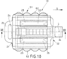
- FIG. 10 shows the device 10 according to the invention schematically in a representation similar to Fig. 6. Here is additionally shown the actuator 51, whereas the Spring elements 48 have been omitted.
- the actuator 51 is displaceable relative to the second part 22 arranged.
- the actuator 51 includes in particular Attack surfaces 62 for a simple, comfortable attack by one User.
- the actuator 51 encompasses the first part 21 and the second part 22 together.
- the first part 21 is relative to the second part 22 due to the Rail-guide arrangement slidably mounted.
- Fig. 7 shows that first part 21 in a position in which it is almost maximal in the second Part 22 is retracted, namely in a position in which the long Flank 32 of tooth 55 on the extreme right in relation to FIG. 7 Corner area 56 of the second part 22 almost touched.
- the pawl 41 is in its locked position, i.e. she lies with its blocking surface 57 on a steep flank 33 of the toothing 31 at.
- a leaf spring 52 lies with its free end 58 on the Pawl 41 on, and loaded the pawl 51 in its locked position into it.
- the leaf spring 52 can, for example, by means of a Fastening groove 61 on the central portion 40 of the second part be attached.
- Fig. 7 shows the first part 21 near its rest position. Also in this state, the spring element 48 is already tensioned and tried the first part 21 relative to the second part 22 with respect to FIG. 7 to move to the right. Since here the flank 32 of the extreme right Tooth 45, however, almost at the corner region 56 of the second part 22 is present, a movement of the first part 21 with respect to FIG almost no longer possible on the right.
- the actuator 21 can start from one position 7 to the right in a position shown in FIG. 8 become. Since in its position shown in Fig. 7 Actuator 51 already with its active surface 54 on one corresponding actuating surface 53 of the pawl 51, leads the displacement of the actuator 51 to pivot the pawl 41 counterclockwise. Through this Pivoting the pawl 41, the pawl 41 from the in Fig. 7 shown locking position in that shown in Fig. 8 Release position shifted. The steep flanks 33 are in the release position the toothing 31 does not engage the locking surfaces 57 of the Pawl 41.
- the first part 21 relative to the second part 22 only along a limited distance B. be moved.
- This route is essentially limited on the one hand through the corner region 56 of the second part 22, to which, as before described, abut a flank 32 of the rightmost tooth 55 can.
- the limited distance B becomes limits that the steep flank 33 of the rightmost tooth 55 on the locking surface 57 of the pawl 41 abuts. Should one Relative movement of the first part 21 to the second part 22 via this limited distance B take place, so here is a safe tightening no longer guaranteed. Basically, it is possible, however Provide any length of the toothing 31 in the blocking direction S.
- a User specifically proceeds to a vehicle security device for example, the security network 11 shown in FIG. 1 to fix and clamp:
- a user can do this in Fig. 7 grasp the actuator 51 shown and the actuator 51st in the tensioning direction S to the fastening point 19 on the vehicle move.
- the arrangement should be such that the Distance between the vehicle-side attachment point 19 and the end area 60 of the vehicle safety device 11 in maximum extended state of the same is such that a Displacement of the actuator 51 relative to the second part 22 of the device 10 is necessary in order to use the fastening projection 34 to reach the vehicle-side attachment point 19 at all can.
- Fig. 9 shows a state of the device 10 in which a relative displacement of the first part 21 with respect to the second part 22 has taken place such that the spring elements 48 are tensioned.
- the Actuator 51 moves this into that shown in FIG. 7 Rest position back.
- the position of the first part 21 shown in FIG. 9 relative to however, the second part 22 implies a tense state of the Spring elements 48. These are constantly striving to ensure that the first part 21st relative to the second part 22 with respect to FIG. 9 to the right relocate, and thus continuously tightening the vehicle safety device 11 to achieve. For example, this is advantageous if one after fastening the vehicle safety device 11 flaccidity occurring in the material web should be balanced. This is particularly advantageous for Vehicle safety devices to be specified Object to be stretched around while driving for example, which causes a certain flaccidity.
- Fig. 9 shows the first part 21 in a working position. This is although not the working position, the maximum distance between vehicle-side attachment point 19 and the end portion 60 of the Security network 11 provides. However, this is a Working position of the first part 21, in which the first part 21 in its Rest position is spring-loaded approximately as shown in FIG. 7.
- the User the actuator 51 again in the blocking direction S.
- the pawl 41 is pivoted, reaches her Release position and allows movement of the first part 21 relatively to the second part 22.
- the fastening end 34 can then be made the fastening eyelet, not shown, are unhooked.
- the device according to the invention serves first of all Determining an end region 60 of a vehicle safety device 11 on a vehicle-side attachment point 19. It meets the highest Safety requirements, even in the event of a crash, because after the Determine a displacement of the first part 21 relative to the second Part 22 is excluded, the distance between the end region 60 the safety device 11 and the vehicle side Attachment point 19 can therefore not be enlarged. simultaneously it ensures constant tightening of the vehicle safety device 11 because the ratchet arrangement in the form of Formrichtgesperres in connection with the spring elements 48 a exerts constant traction. Ultimately, the device is also easy to use because one user only needs the actuator 51 must take and so a one-handed movement to set is possible.
- Spring elements 48 which are designed as a compression spring, between the first part 21 and the second part 22 to arrange a tension spring however equally for a provision of the first part 21 relative to the second part 22 in the rest position of the first part 21.
Landscapes
- Engineering & Computer Science (AREA)
- Mechanical Engineering (AREA)
- Lock And Its Accessories (AREA)
- Clamps And Clips (AREA)
- Emergency Lowering Means (AREA)
Applications Claiming Priority (2)
| Application Number | Priority Date | Filing Date | Title |
|---|---|---|---|
| DE10046142 | 2000-09-15 | ||
| DE2000146142 DE10046142B4 (de) | 2000-09-15 | 2000-09-15 | Vorrichtung zur Festlegung eines Endbereiches einer Fahrzeug- Sicherheitseinrichtung an einem fahrzeugseitigen Befestigungspunkt sowie zur Spannung des Endbereichs der Fahrzeug-Sicherheitseinrichtung relativ zu dem Befestigungspunkt |
Publications (2)
| Publication Number | Publication Date |
|---|---|
| EP1188621A2 true EP1188621A2 (fr) | 2002-03-20 |
| EP1188621A3 EP1188621A3 (fr) | 2003-11-26 |
Family
ID=7656653
Family Applications (1)
| Application Number | Title | Priority Date | Filing Date |
|---|---|---|---|
| EP01117280A Withdrawn EP1188621A3 (fr) | 2000-09-15 | 2001-07-18 | Dispositif de fixation d'une extrémité d'un système de sécurité dans un véhicule et mise sous tension de celle-ci |
Country Status (2)
| Country | Link |
|---|---|
| EP (1) | EP1188621A3 (fr) |
| DE (1) | DE10046142B4 (fr) |
Cited By (2)
| Publication number | Priority date | Publication date | Assignee | Title |
|---|---|---|---|---|
| DE102004036781A1 (de) * | 2004-07-29 | 2006-03-23 | Hs Products Engineering Gmbh | Kindersitz |
| US20150021926A1 (en) * | 2013-07-19 | 2015-01-22 | Amsafe Commercial Products, Inc. | Latch device and anchor with swivel coupling |
Families Citing this family (2)
| Publication number | Priority date | Publication date | Assignee | Title |
|---|---|---|---|---|
| DE102004050546B4 (de) * | 2004-10-16 | 2022-02-24 | Bayerische Motoren Werke Aktiengesellschaft | Rückhalteeinrichtung für Gepäckstücke in einem Fahrzeug |
| DE102005043768B3 (de) * | 2005-09-13 | 2007-03-01 | Dr.Ing.H.C. F. Porsche Ag | Schutzeinrichtung für Fahrzeuginsassen |
Citations (2)
| Publication number | Priority date | Publication date | Assignee | Title |
|---|---|---|---|---|
| EP0642955B1 (fr) | 1993-09-15 | 1997-12-17 | Ieper Industries N.V. | Installation de retenue |
| DE19835230A1 (de) | 1998-08-04 | 2000-02-17 | Baumeister & Ostler Gmbh Co | Einfaches Rückhaltenetz mit unnachgiebigen Haltebändern |
Family Cites Families (6)
| Publication number | Priority date | Publication date | Assignee | Title |
|---|---|---|---|---|
| DE2749560A1 (de) * | 1977-11-05 | 1979-05-10 | Eugen Seitz | Vorrichtung zum abteilen des hinteren laderaumes vom fahrgastraum eines fuer den transport von personen und lasten ausgelegten kraftfahrzeuges (kombifahrzeug) |
| DE19643691C2 (de) * | 1996-10-23 | 2000-03-23 | Baumeister & Ostler Gmbh Co | Sicherheitsnetzanordnung |
| DE19708192C5 (de) * | 1997-02-28 | 2006-08-03 | Bos Gmbh & Co. Kg | Laderaum-Trennvorrichtung für Kraftwagen, insbesondere für Kombinations-Personenkraftwagen |
| DE19729660C1 (de) * | 1997-07-11 | 1998-08-27 | Butz Peter Verwaltung | Rückhalte- bzw. Trennvorrichtung für Kraftwagen, mit einer Rückhaltebahn |
| FR2768102B1 (fr) * | 1997-09-05 | 1999-10-29 | Renault | Dispositif de seraration d'un volume de chargement de l'habitacle d'un vehicule de transport de passagers et de charges |
| DE59810525D1 (de) * | 1997-11-10 | 2004-02-05 | Bos Gmbh | Sicherheitseinrichtung für Kraftfahrzeuge, insbesondere Laderaumtrennvorrichtung für Kombinations-Personenkraftwagen od. dgl |
-
2000
- 2000-09-15 DE DE2000146142 patent/DE10046142B4/de not_active Expired - Fee Related
-
2001
- 2001-07-18 EP EP01117280A patent/EP1188621A3/fr not_active Withdrawn
Patent Citations (2)
| Publication number | Priority date | Publication date | Assignee | Title |
|---|---|---|---|---|
| EP0642955B1 (fr) | 1993-09-15 | 1997-12-17 | Ieper Industries N.V. | Installation de retenue |
| DE19835230A1 (de) | 1998-08-04 | 2000-02-17 | Baumeister & Ostler Gmbh Co | Einfaches Rückhaltenetz mit unnachgiebigen Haltebändern |
Cited By (4)
| Publication number | Priority date | Publication date | Assignee | Title |
|---|---|---|---|---|
| DE102004036781A1 (de) * | 2004-07-29 | 2006-03-23 | Hs Products Engineering Gmbh | Kindersitz |
| DE102004036781B4 (de) * | 2004-07-29 | 2008-09-25 | Hs Products Engineering Gmbh | Kindersitz |
| US20150021926A1 (en) * | 2013-07-19 | 2015-01-22 | Amsafe Commercial Products, Inc. | Latch device and anchor with swivel coupling |
| US9718427B2 (en) * | 2013-07-19 | 2017-08-01 | Shield Restraint Sytems, Inc. | Latch device and anchor with swivel coupling |
Also Published As
| Publication number | Publication date |
|---|---|
| EP1188621A3 (fr) | 2003-11-26 |
| DE10046142A1 (de) | 2002-04-04 |
| DE10046142B4 (de) | 2006-08-24 |
Similar Documents
| Publication | Publication Date | Title |
|---|---|---|
| DE69019765T2 (de) | Spannungsverminderndes Sicherheitsgurtsystem. | |
| DE3726711C2 (fr) | ||
| DE69413706T2 (de) | Vormontierte trägereinheit für die funktionsteile eines sicherheitsgurtsystems | |
| EP0345438A2 (fr) | Rideau écran on dispositif pour un coffre de véhicule automobile | |
| EP1102691B1 (fr) | Filet de retenue simple muni de bandes de retenue | |
| DE1680142A1 (de) | Sicherheitsvorrichtung in Fahrzeugen zum Schutz der Insassen | |
| EP0642955A1 (fr) | Installation de retenue | |
| DE2423969B2 (de) | Feststellvorrichtung für längsverschiebbare Fahrzeugsitze | |
| DE102007046958A1 (de) | Energieabsorptions-Sitzverankerungs-Rückhaltesystem für Kinder-Sicherheitssitze | |
| DE1755287A1 (de) | Einbauvorrichtung fuer Fahrzeug-Sicherheitsgurt | |
| DE69518562T2 (de) | Gurtspannvorrichtung für Sicherheitsgurt | |
| DE10046203A1 (de) | Zusatzverriegelung für Fahrzeugsitz-Längseinstellvorrichtung | |
| EP0300470A1 (fr) | Dispositif de couplage d'un support muni d'un dispositif d'accrochage pour ceinture de sécurité sur une pièce d'attache fixée au véhicule | |
| WO2009086897A2 (fr) | Auxiliaire de montage et procédé de montage | |
| DE102018219325B4 (de) | Lastbegrenzer und Sicherheitsgurt mit plattenförmigem Lastbegrenzer | |
| DE69411560T2 (de) | Vorrichtung zur längseinstellung von fahrzeugsitzen | |
| EP1188621A2 (fr) | Dispositif de fixation d'une extrémité d'un système de sécurité dans un véhicule et mise sous tension de celle-ci | |
| DE102013002948A1 (de) | Gurtschlossbringer | |
| DE9305221U1 (de) | Gurtstraffer für Fahrzeugsicherheitsgurte | |
| DE3229260C2 (de) | Rückstrammer für ein Sicherheitsgurtsystem für Kraftfahrzeuge | |
| DE102014005565B4 (de) | Arretiervorrichtung zum Verkürzen der freien Gurtlänge und Fahrzeug mit einer solchen Arretiervorrichtung | |
| DE20016205U1 (de) | Vorrichtung zur Festlegung eines Endbereiches einer Fahrzeug-Sicherheitseinrichtung an einem fahrzeugseitigen Befestigungspunkt sowie zur Spannung des Endbereiches der Fahrzeug-Sicherheitseinrichtung relativ zu dem Befestigungspunkt | |
| DE3401529A1 (de) | Verstellvorrichtung fuer einen sicherheitsgurt-anlenkpunkt | |
| EP2767442A1 (fr) | Dispositif de protection de soutènement d'un véhicule utilitaire et véhicule utilitaire équipé d'un tel dispositif | |
| DE102005050223A1 (de) | Kopfstütze eines Kraftfahrzeugsitzes mit oberem und unterem Führungsbereich |
Legal Events
| Date | Code | Title | Description |
|---|---|---|---|
| PUAI | Public reference made under article 153(3) epc to a published international application that has entered the european phase |
Free format text: ORIGINAL CODE: 0009012 |
|
| AK | Designated contracting states |
Kind code of ref document: A2 Designated state(s): AT BE CH CY DE DK ES FI FR GB GR IE IT LI LU MC NL PT SE TR |
|
| AX | Request for extension of the european patent |
Free format text: AL;LT;LV;MK;RO;SI |
|
| PUAL | Search report despatched |
Free format text: ORIGINAL CODE: 0009013 |
|
| AK | Designated contracting states |
Kind code of ref document: A3 Designated state(s): AT BE CH CY DE DK ES FI FR GB GR IE IT LI LU MC NL PT SE TR |
|
| AX | Request for extension of the european patent |
Extension state: AL LT LV MK RO SI |
|
| RAP1 | Party data changed (applicant data changed or rights of an application transferred) |
Owner name: BOS GMBH & CO. KG |
|
| 17P | Request for examination filed |
Effective date: 20031110 |
|
| AKX | Designation fees paid |
Designated state(s): DE FR GB |
|
| 17Q | First examination report despatched |
Effective date: 20040902 |
|
| GRAP | Despatch of communication of intention to grant a patent |
Free format text: ORIGINAL CODE: EPIDOSNIGR1 |
|
| STAA | Information on the status of an ep patent application or granted ep patent |
Free format text: STATUS: THE APPLICATION IS DEEMED TO BE WITHDRAWN |
|
| 18D | Application deemed to be withdrawn |
Effective date: 20090218 |