EP0643207A1 - Gasturbine mit Druckwellenbrenner, Zwischen-Überhitzung und Gasrückführung - Google Patents
Gasturbine mit Druckwellenbrenner, Zwischen-Überhitzung und Gasrückführung Download PDFInfo
- Publication number
- EP0643207A1 EP0643207A1 EP94112874A EP94112874A EP0643207A1 EP 0643207 A1 EP0643207 A1 EP 0643207A1 EP 94112874 A EP94112874 A EP 94112874A EP 94112874 A EP94112874 A EP 94112874A EP 0643207 A1 EP0643207 A1 EP 0643207A1
- Authority
- EP
- European Patent Office
- Prior art keywords
- pressure
- low
- gas
- turbine
- pressure turbine
- Prior art date
- Legal status (The legal status is an assumption and is not a legal conclusion. Google has not performed a legal analysis and makes no representation as to the accuracy of the status listed.)
- Granted
Links
Images

Classifications
-
- F—MECHANICAL ENGINEERING; LIGHTING; HEATING; WEAPONS; BLASTING
- F02—COMBUSTION ENGINES; HOT-GAS OR COMBUSTION-PRODUCT ENGINE PLANTS
- F02C—GAS-TURBINE PLANTS; AIR INTAKES FOR JET-PROPULSION PLANTS; CONTROLLING FUEL SUPPLY IN AIR-BREATHING JET-PROPULSION PLANTS
- F02C3/00—Gas-turbine plants characterised by the use of combustion products as the working fluid
- F02C3/02—Gas-turbine plants characterised by the use of combustion products as the working fluid using exhaust-gas pressure in a pressure exchanger to compress combustion-air
-
- F—MECHANICAL ENGINEERING; LIGHTING; HEATING; WEAPONS; BLASTING
- F02—COMBUSTION ENGINES; HOT-GAS OR COMBUSTION-PRODUCT ENGINE PLANTS
- F02C—GAS-TURBINE PLANTS; AIR INTAKES FOR JET-PROPULSION PLANTS; CONTROLLING FUEL SUPPLY IN AIR-BREATHING JET-PROPULSION PLANTS
- F02C3/00—Gas-turbine plants characterised by the use of combustion products as the working fluid
- F02C3/34—Gas-turbine plants characterised by the use of combustion products as the working fluid with recycling of part of the working fluid, i.e. semi-closed cycles with combustion products in the closed part of the cycle
-
- F—MECHANICAL ENGINEERING; LIGHTING; HEATING; WEAPONS; BLASTING
- F02—COMBUSTION ENGINES; HOT-GAS OR COMBUSTION-PRODUCT ENGINE PLANTS
- F02C—GAS-TURBINE PLANTS; AIR INTAKES FOR JET-PROPULSION PLANTS; CONTROLLING FUEL SUPPLY IN AIR-BREATHING JET-PROPULSION PLANTS
- F02C6/00—Plural gas-turbine plants; Combinations of gas-turbine plants with other apparatus; Adaptations of gas-turbine plants for special use
- F02C6/003—Gas-turbine plants with heaters between turbine stages
Definitions
- the invention relates to a method for operating a gas turbine system, in which the air processed in a compressor is mixed with a fuel downstream of the compression and is fed and burned to a pressure wave machine working with isochoric or isobaric combustion, and then a high pressure and a pressure gas are obtained with the working gas thus obtained Low pressure gas turbine can be applied.
- EP 0 468 083 describes a method in which the combustion of the fuel / air mixture takes place in the rotor cells of a pressure wave machine at a constant volume and a part of the working gas formed by the combustion in the rotor cells acts on a high-pressure gas turbine and the rest of the rotor cells acted on a low pressure gas turbine.
- a homogeneous fuel distribution in the longitudinal direction of the cells is generated in the pressure wave machine.
- the applicant is aware of a method for operating a gas turbine system with a pressure wave machine working with isochoric combustion, in which the compressed air is enriched with fuel in different layers, so that e.g. a layer with a rich and a layer with a lean fuel / air mixture is formed.
- the layers are expanded to the same temperature after combustion and the more fuel-enriched portion is fed to the high-pressure turbine and the less fuel-enriched portion to the low-pressure turbine.
- the efficiency of the system is increased compared to the method disclosed in EP 0 468 083.
- a gas turbine system in which the hot gas flow from the low-pressure propellant gas line connected to the pressure wave machine with the hot gas flow that emerges from the high-pressure turbine, i.e. with partially expanded and cooled gas from the high-pressure turbine, in the low-pressure turbine or in part is mixed before entering the low pressure turbine.
- the hot gas flows of different temperatures By mixing the hot gas flows of different temperatures, the inlet temperature of the gas in the low-pressure turbine is reduced, which has an unfavorable effect on the efficiency.
- the invention tries to avoid all these disadvantages. It is based on the task of creating a method for operating a gas turbine system according to the preamble of claim 1, which is very good due to minimal NO x emissions Part load behavior and an improved efficiency compared to the known prior art.
- the advantages of the invention include the high power density, the very high efficiency, the very good part-load behavior and the very low NO x emission values.
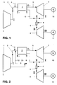
- a low-pressure compressor 1 supplies pre-compressed air to a pressure wave machine 3 via a low-pressure line 2.
- the term low pressure is not to be understood absolutely here, but is only low in comparison to the remaining pressure level of the gas turbine system .
- a fuel 4 for example natural gas, is added to the pre-compressed air in front of the pressure wave machine 3. So that the system can also work under partial load conditions, the nozzles for switching on the fuel can be switched on in stages. This is also important in view of low NO x emission values.
- the fuel / air mixture arrives in the pressure wave machine 3 and is used there in a known manner, e.g. in EP 0 468 083, burned under isochoric conditions.
- the gases thus prepared are then passed through a high-pressure propellant line 5 or a low-pressure propellant line 6 and act on the high-pressure turbine 7 or the low-pressure turbine 8, which drive the generators 10, 11.
- the compressed air can also be enriched with fuel to different extents, so that a layer with a rich and a lean mixture of fuel / air is formed.
- the layers are relaxed to the same temperature after combustion and the more fuel-enriched portion is fed to the high-pressure turbine 7 and the less fuel-enriched portion to the low-pressure turbine 8.
- the gas which may be hotter under certain circumstances, from the low-pressure propellant gas line 6 is mixed into the partially relaxed and correspondingly cooled gas.
- this mixture is subjected to reheating in that fuel 4 is injected and the gas is burned in a combustion chamber 9.
- the gas which has been treated in this way is then applied to the low-pressure turbine 8.
- the intermediate overheating supplies the low-pressure turbine 8 with gas at a temperature at a higher level than in the prior art, which leads to an improvement in efficiency.
- these propellant gases are then expanded to a back pressure which corresponds to the atmospheric pressure.
- FIG. 3 shows the temperature profile of the gas over time, the Roman numerals corresponding to the times or locations which are also identified with Roman numerals in the process diagram according to FIG. 1.
- the time-temperature diagram shown in FIG. 3 shows that the intermediate superheating achieves a temperature gain of T before the gas enters the low-pressure turbine 8. This protects the turbine, which has an advantageous effect on the overall process.
- the further combustion chamber 9 according to the invention more control options are also available in the overall process, so that a very good part-load behavior of the system is achieved.
- the method according to the invention can also be used for gas turbine systems in which pressure wave machines 3 are used, which work with isobaric combustion of the gas and drive the generators 10 and 11 via high-pressure turbines 7 and low-pressure turbines 8.
- exhaust gas recirculation is additionally provided.
- the main advantage of this variant is that there is only minimal energy loss.
- part of this exhaust gas is branched off, mixed with part of the air compressed in the compressor 1 and via an exhaust gas line 12 and a throttle valve 13 in the low-pressure line 2, shortly before entering the pressure wave machine, returned.
- the extinguishing limit of the burner is increased, the efficiency of the system increases, and the lowest possible NO x emissions for environmental reasons are greatly reduced.
- the mixture of the relatively hot exhaust gas with a portion of the cold air coming from the compressor 1 has the advantage that the exhaust gas line 12 is not subjected to excessive thermal stress when the gases flow through.
Landscapes
- Engineering & Computer Science (AREA)
- Chemical & Material Sciences (AREA)
- Combustion & Propulsion (AREA)
- Mechanical Engineering (AREA)
- General Engineering & Computer Science (AREA)
- Life Sciences & Earth Sciences (AREA)
- Sustainable Development (AREA)
- Engine Equipment That Uses Special Cycles (AREA)
- Supercharger (AREA)
Abstract
Description
- Die Erfindung betrifft ein Verfahren zum Betrieb einer Gasturbinenanlage, bei dem die in einem Verdichter aufbereitete Luft stromab der Verdichtung mit einem Brennstoff gemischt und einer mit isochorer oder isobarer Verbrennung arbeitenden Druckwellenmaschine zugeführt und verbrannt wird und anschliessend mit dem so erhaltenen Arbeitsgas eine Hochdruck- und eine Niederdruck-Gasturbine beaufschlagt werden.
- Derartige verfahren zur Aufbereitung des Arbeitsgases in Gasturbinenanlagen sind bekannt.
- So wird z.B. in EP 0 468 083 ein Verfahren beschrieben, bei dem die Verbrennung des Brennstoff/Luft-Gemisches in den Rotorsellen einer Druckwellenmaschine bei konstantem Volumen erfolgt und ein Teil des durch die Verbrennung in den Rotorzellen sich bildenden Arbeitsgases eine Hochdruck-Gasturbine beaufschlagt und der restliche Teil aus den Rotorzellen eine Niederdruck-Gasturbine beaufschlagt. In der Druckwellenmaschine wird im Betrieb eine homogene Brennstoffverteilung in Längsrichtung der Zellen erzeugt. Daraus ergeben sich Probleme, wenn an diese Druckwellenmaschine sowohl eine Niederdruck- als auch eine Hochdruck-Turbine angeschlossen werden, denn man ist bestrebt, zur Wirkungzgradverbesserung beide Turbinen bei derselben optimalen Temperatur zu betreiben, obwohl die Gase der Hochdruck-Turbine und der Niederdruck-Turbine bei unterschiedlichen Drücken zugeführt werden.
- Der Anmelderin ist ein Verfahren zum Betrieb einer Gasturbinenanlage mit einer mit isochorer Verbrennung arbeitenden Druckwellenmaschine bekannt, bei der die verdichtete Luft schichtweise unterschiedlich mit Brennstoff angereichert wird, so dass z.B. eine Schicht mit einem fetten und eine Schicht mit einem mageren Brennstoff/Luft-Gemisch entsteht. Die Schichten werden nach der Verbrennung auf dieselbe Temperatur entspannt und die stärker mit Brennstoff angereicherte Teilmenge wird der Hochdruck-Turbine und die schwächer mit Brennstoff angereicherte Teilmenge der Niederdruck-Turbine zugeführt. Dadurch wird gegenüber dem in EP 0 468 083 offenbarten Verfahren der Wirkungsgrad der Anlage erhöht.
- Ausserdem ist eine Gasturbinenanlage bekannt, bei der der Heissgasstrom aus der an der Druckwellenmaschine angeschlossenen Niederdruck-Treibgasleitung mit dem Heissgasstrom, der aus der Hochdruckturbine austritt, also mit teilentspanntem und abgekühltem Gas aus der Hochdruck-Turbine, in der Niederdruck-Turbine bzw. zum Teil vor dem Eintritt in die Niederdruck-Turbine gemischt wird. Durch Mischen der Heissgasströme unterschiedlicher Temperatur wird die Eintrittstemperatur des Gases in die Niederdruck-Turbine herabgesetzt, was sich ungünstig auf den Wirkungsgrad auswirkt.
- Die Erfindung versucht, all diese Nachteile zu vermeiden. Ihr liegt die Aufgabe zugrunde, ein Verfahren zum Betrieb einer Gasturbinenanlage gemäss Oberbegriff des Anspruches 1 zu schaffen, das sich durch miminale NOx-Emissionen, sehr gutes Teillastverhalten und einen verbesserten Wirkungsgrad gegenüber dem bekannten Stand der Technik auszeichnet.
- Erfindungsgemäss wird dies bei einem Verfahren zum Betrieb einer Gasturbinenanlage, bei dem die in einem Verdichter aufbereitete Luft stromab der Verdichtung mit einem Brennstoff gemischt und einer mit isochorer oder isobarer Verbrennung arbeitenden Druckwellenmaschine zugeführt und verbrannt wird und anschliessend mit dem so erhaltenen Arbeitsgas eine Hochdruck- und eine Niederdruck-Gasturbine beaufschlagt werden, wobei dem von der Druckwellenmaschine zur Niederdruck-Turbine geleiteten Teilmengenstrom vor dem Eintritt in die Niederdruck-Turbine teilentspanntes und abgekühltes Gas aus der Hochdruck-Turbine zugemischt wird, dadurch gelöst, dass im Anschluss an diese Zumischung Brennstoff eingedüst wird und danach das Gemisch in einer Brennkammer verbrannt wird.
- Die Vorteile der Erfindung liegen unter anderem in der hohen Leistungsdichte, dem sehr hohen Wirkungsgrad, dem sehr guten Teillastverhalten und den sehr niedrigen NOx-Emissionswerten.
- Es ist besonders zweckmässig, wenn ein Teil des Gemisches aus teilentspanntem und abgekühltem Abgas der Hochdruck-Turbine und aus dem aus der Druckwellenmaschine zur Niederdruck-Turbine geleiteten Teilmengenstrom vor der Eindüsung von Brennstoff zur Zwischenüberhitzung abgezweigt wird, mit einem Teil der im Verdichter komprimierten Luft gemischt wird und über eine Abgas-Leitung und eine Drosselklappe in die Niederdruck-Leitung, kurz vor dem Eintritt in die Druckwellenmaschine, zurückgeführt wird.
- Auf Grund dieser Abgasrückführung treten vorteilhafterweise nur minimale Energieverluste auf.
- In der Zeichnung sind zwei Ausführungsbeispiele der Erfindung dargestellt.
Es zeigen: - Fig. 1
- ein Verfahrensschema zum Betrieb einer Gasturbinenanlage mit einer mit isochorer Verbrennung arbeitenden Druckwellenmaschine ohne Abgasrückführung;
- Fig. 2
- ein Verfahrensschema zum Betrieb einer Gasturbinenanlage mit einer mit isochorer Verbrennung arbeitenden Druckwellenmaschine mit Abgasrückführung;
- Fig. 3
- ein Zeit-Temperatur-Diagramm für das Arbeitsgas.
- Es sind nur die für das Verständnis der Erfindung wesentlichen Elemente gezeigt. Die Strömungsrichtung der Arbeitsmittel ist mit Pfeilen bezeichnet.
- Nachfolgend wird die Erfindung anhand von Ausführungsbeispielen und der Figuren 1 bis 3 näher erläutert.
- Bei der in Fig. 1 schematisch dargestellten Gasturbinenanlage liefert ein Niederdruck-Verdichter 1 über eine Niederdruck-Leitung 2 vorverdichtete Luft in eine Druckwellenmaschine 3. Der Begriff Niederdruck ist hier nicht absolut zu verstehen, sondern er ist nur niedrig im Vergleich zum übrigen Druckniveau der Gasturbinenanlage. Vor der Druckwellenmaschine 3 wird der vorverdichteten Luft ein Brennstoff 4, beispielsweise Erdgas, zugemischt. Damit die Anlage auch unter Teillastbedingungen arbeiten kann, sind die Düsen zur Brennstoffzuschaltung stufenweise zuschaltbar. Das ist auch im Hinblick auf niedrige NOx-Emissionswerte wichtig.
- Das Brennstoff/Luft-Gemisch gelangt in die Druckwellenmaschine 3 und wird dort in bekannter Weise, wie z.B. in EP 0 468 083 beschrieben, unter isochoren Bedingungen verbrannt. Die so aufbereiteten Gase werden dann über eine Hochdruck-Treibgasleitung 5 bzw. eine Niederdruck-Treibgasleitung 6 geleitet und beaufschlagen die Hochdruck-Turbine 7 bzw. die Niederdruck-Turbine 8, welche die Generatoren 10, 11 antreiben.
- Selbstverständlich kann die verdichtete Luft auch schichtweise unterschiedlich stark mit Brennstoff angereichert werden, so dass eine Schicht mit einem fetten und eine Schicht mit einem mageren Brennstoff/Luft-Gemisch entsteht. Die Schichten werden nach der Verbrennung auf dieselbe Temperatur entspannt und die stärker mit Brennstoff angereicherte Teilmenge wird der Hochdruck-Turbine 7 und die schwächer mit Brennstoff angereicherte Teilmenge der Niederdruck-Turbine 8 zugeführt.
- Nach dem Hochdruckteil wird dem teilentspannten und entsprechend abgekühlten Gas das unter Umständen heissere Gas aus der Niederdruck-Treibgasleitung 6 zugemischt. Dieses Gemisch wird erfindungsgemäss einer Zwischenüberhitzung ausgesetzt, indem Brennstoff 4 eingedüst wird und das Gas in einer Brennkammer 9 verbrannt wird. Anschliessend wird mit dem so aufbereiteten Gas die Niederdruck-Turbine 8 beaufschlagt. Durch die Zwischenüberhitzung wird der Niederdruck-Turbine 8 Gas mit einer Temperatur auf einem höheren Niveau im Vergleich zum Stand der Technik zugeführt, was zu einer Wirkungsgradverbesserung führt. In der Niederdruck-Turbine 8 werden diese Treibgase dann auf einen Gegendruck entspannt, der dem Atmosphärendruck entspricht.
- In Fig. 3 ist der zeitliche Temperaturverlauf des Gases abgebildet, wobei die römischen Ziffern den Zeitpunkten bzw. Orten entsprechen, die im Verfahrensschema nach Fig. 1 ebenfalls mit römischen Ziffern gekennzeichnet sind.
- Aus dem in Fig. 3 dargestellten Zeit-Temperatur-Diagramm geht hervor, dass durch die Zwischenüberhitzung ein Temperaturgewinn von _T vor Eintritt des Gases in die Niederdruck-Turbine 8 erzielt wird. Dadurch wird die Turbine geschont, was sich vorteilhaft auf den Gesamtprozess auswirkt. Durch den erfindungsgemässen Einsatz der weiteren Brennkammer 9 sind im Gesamtverfahren ausserdem mehr Regelmöglichkeiten vorhanden, so dass ein sehr gutes Teillastverhalten der Anlage erreicht wird.
- Selbstverständlich kann das erfindungsgemässe Verfahren auch für Gasturbinenanlagen angewendet werden, bei denen Druckwellenmaschinen 3 eingesetzt werden, welche mit isobarer Verbrennung des Gases arbeiten und über Hochdruck-Turbinen 7 bzw. Niederdruck-Turbinen 8 die Generatoren 10 bzw. 11 antreiben.
- In einem anderen Ausführungsbeispiel (siehe Fig. 2) ist zusätzlich eine Abgasrückführung vorgesehen. Der Hauptvorteil dieser Variante besteht darin, dass nur minimale Energieverluste auftreten. Nach der Mischung des teilentspannten und entsprechend abgekühlten Abgases aus der Hochdruck-Turbine 7 mit dem unter Umständen heisseren Gas aus der Niederdruck-Treibgasleitung 6 wird ein Teil dieses Abgases abgezweigt, mit einem Teil der im Verdichter 1 komprimierten Luft gemischt und über eine Abgas-Leitung 12 und eine Drosselklappe 13 in die Niederdruck-Leitung 2, kurz vor dem Eintritt in die Druckwellenmaschine, zurückgeführt. Dadurch wird die Löschgrenze des Brenners erhöht, der Wirkungsgrad der Anlage steigt, und die aus umwelttechnischen Aspekten möglichst geringen NOx-Emissionen werden stark reduziert. Die Mischung des relativ heissen Abgases mit einem Teil der vom Verdichter 1 kommenden kalten Luft hat den Vorteil, dass die Abgas-Leitung 12 beim Durchströmen der Gase nicht zu sehr thermisch beansprucht wird.
-
- 1
- Niederdruck-Verdichter
- 2
- Niederdruck-Leitung
- 3
- Druckwellenmaschine
- 4
- Brennstoff
- 5
- Hochdruck-Treibgasleitung
- 6
- Niederdruck-Treibgasleitung
- 7
- Hochdruck-Turbine
- 8
- Niederdruck-Turbine
- 9
- Brennkammer
- 10
- Generator
- 11
- Generator
- 12
- Abgas-Leitung
- 13
- Drosselklappe
Claims (2)
- Verfahren zum Betrieb einer Gasturbinenanlage, bei dem die in einem Niederdruck-Verdichter (1) aufbereitete Luft stromab der Verdichtung mit einem Brennstoff (4) gemischt und einer mit isochorer oder isobarer Verbrennung arbeitenden Druckwellenmaschine (3) zugeführt und verbrannt wird und anschliessend mit dem so erhaltenen Arbeitsgas über eine Hochdruck-Treibgasleitung (5) eine Hochdruck-Turbine (7) und über eine Niederdruck-Treibgazleitung (6) eine Niederdruck-Turbine (8) beaufschlagt werden, wobei dem von der Druckwellenmaschine (3) zur Niederdruck-Turbine (8) geleiteten Teilmengenstrom vor dem Eintritt in die Niederdruck-Turbine (8) teilentspanntes und abgekühltes Gas aus der Hochdruck-Turbine (7) zugemischt wird, dadurch gekennzeichnet, dass nach der Zumischung Brennstoff (4) eingedüst wird und das Gemisch in einer Brennkammer (9) verbrannt wird.
- Verfahren nach Anspruch 1, dadurch gekennzeichnet, dass ein Teil des Gemisches aus teilentspanntem und abgekühltem Abgas der Hochdruck-Turbine (7) und aus dem aus der Druckwellenmaschine zur Niederdruck-Turbine (8) geleiteten Teilmengenstrom vor der Eindüsung von Brennstoff (4) zur Zwischenüberhitzung abgezweigt wird, mit einem Teil der im Verdichter komprimierten Luft gemischt wird und über eine Abgas-Leitung (12) und eine Drosselklappe (13) in die Niederdruck-Leitung (2), kurz vor dem Eintritt in die Druckwellenmaschine (3), zurückgeführt wird.
Applications Claiming Priority (2)
| Application Number | Priority Date | Filing Date | Title |
|---|---|---|---|
| DE4331081A DE4331081A1 (de) | 1993-09-13 | 1993-09-13 | Verfahren zum Betrieb einer Gasturbinenanlage |
| DE4331081 | 1993-09-13 |
Publications (2)
| Publication Number | Publication Date |
|---|---|
| EP0643207A1 true EP0643207A1 (de) | 1995-03-15 |
| EP0643207B1 EP0643207B1 (de) | 1998-06-17 |
Family
ID=6497618
Family Applications (1)
| Application Number | Title | Priority Date | Filing Date |
|---|---|---|---|
| EP94112874A Expired - Lifetime EP0643207B1 (de) | 1993-09-13 | 1994-08-18 | Gasturbine mit Druckwellenbrenner, Zwischen-Überhitzung und Gasrückführung |
Country Status (4)
| Country | Link |
|---|---|
| US (1) | US5557919A (de) |
| EP (1) | EP0643207B1 (de) |
| JP (1) | JPH07150975A (de) |
| DE (2) | DE4331081A1 (de) |
Families Citing this family (23)
| Publication number | Priority date | Publication date | Assignee | Title |
|---|---|---|---|---|
| RU2157900C2 (ru) * | 1996-03-26 | 2000-10-20 | Ахметов Виталий Галеевич | Низкотемпературный газотурбинный (реактивный, винтовой, турбовальный) двигатель |
| US5916125A (en) | 1997-05-16 | 1999-06-29 | Allison Engine Company, Inc. | Forced purge wave rotor |
| US5924305A (en) * | 1998-01-14 | 1999-07-20 | Hill; Craig | Thermodynamic system and process for producing heat, refrigeration, or work |
| US6449939B1 (en) | 2000-05-26 | 2002-09-17 | Rolls-Royce Corporation | Pulsed detonation engine wave rotor |
| GB2373299B (en) * | 2001-03-12 | 2004-10-27 | Alstom Power Nv | Re-fired gas turbine engine |
| US7621118B2 (en) * | 2002-07-03 | 2009-11-24 | Rolls-Royce North American Technologies, Inc. | Constant volume combustor having a rotating wave rotor |
| RU2290521C2 (ru) * | 2004-06-21 | 2006-12-27 | Владислав Сергеевич Буриков | Газотурбинный двигатель |
| US20090301054A1 (en) * | 2008-06-04 | 2009-12-10 | Simpson Stanley F | Turbine system having exhaust gas recirculation and reheat |
| US9297306B2 (en) * | 2008-09-11 | 2016-03-29 | General Electric Company | Exhaust gas recirculation system, turbomachine system having the exhaust gas recirculation system and exhaust gas recirculation control method |
| US8713947B2 (en) | 2011-08-25 | 2014-05-06 | General Electric Company | Power plant with gas separation system |
| US8453462B2 (en) | 2011-08-25 | 2013-06-04 | General Electric Company | Method of operating a stoichiometric exhaust gas recirculation power plant |
| US8453461B2 (en) | 2011-08-25 | 2013-06-04 | General Electric Company | Power plant and method of operation |
| US8245492B2 (en) | 2011-08-25 | 2012-08-21 | General Electric Company | Power plant and method of operation |
| US8266913B2 (en) | 2011-08-25 | 2012-09-18 | General Electric Company | Power plant and method of use |
| US8205455B2 (en) | 2011-08-25 | 2012-06-26 | General Electric Company | Power plant and method of operation |
| US8266883B2 (en) | 2011-08-25 | 2012-09-18 | General Electric Company | Power plant start-up method and method of venting the power plant |
| US8347600B2 (en) | 2011-08-25 | 2013-01-08 | General Electric Company | Power plant and method of operation |
| US9127598B2 (en) | 2011-08-25 | 2015-09-08 | General Electric Company | Control method for stoichiometric exhaust gas recirculation power plant |
| US9708977B2 (en) | 2012-12-28 | 2017-07-18 | General Electric Company | System and method for reheat in gas turbine with exhaust gas recirculation |
| WO2014071118A1 (en) * | 2012-11-02 | 2014-05-08 | General Electric Company | System and method for reheat in gas turbine with exhaust gas recirculation |
| US9574490B2 (en) | 2013-07-23 | 2017-02-21 | Cummins Inc. | Interstage gas injection for multi-stage turbocharged natural gas engine |
| CN105774512B (zh) * | 2016-03-01 | 2018-09-14 | 至玥腾风科技投资集团有限公司 | 一种发动机前置的增程式电动乘用车 |
| FR3091899B1 (fr) * | 2019-01-22 | 2020-12-25 | Safran Aircraft Engines | Ensemble pour turbomachine |
Citations (9)
| Publication number | Priority date | Publication date | Assignee | Title |
|---|---|---|---|---|
| CH250742A (de) * | 1946-07-05 | 1947-09-15 | Escher Wyss Maschf Ag | Wärmekraftanlage mit mindestens zwei in Reihe geschalteten und mit voneinander unabhängigen Drehgeschwindigkeiten laufenden Verbrennungsturbinen. |
| US2461186A (en) * | 1942-02-20 | 1949-02-08 | Bbc Brown Boveri & Cie | Gas turbine installation |
| GB2229733A (en) * | 1989-03-24 | 1990-10-03 | Gen Electric | Hydrocarbon combustion apparatus and method |
| EP0468083A1 (de) * | 1990-07-27 | 1992-01-29 | Asea Brown Boveri Ag | Verfahren zur Aufbereitung des Arbeitsgases in einer Gasturbinenanlage |
| EP0474894A1 (de) * | 1990-09-10 | 1992-03-18 | Asea Brown Boveri Ag | Gasturbinenanordnung |
| EP0474893A1 (de) * | 1990-09-10 | 1992-03-18 | Asea Brown Boveri Ag | Gasturbinenanordnung |
| EP0549930A1 (de) * | 1991-12-31 | 1993-07-07 | Asea Brown Boveri Ag | Gasturbogruppe |
| EP0582809A1 (de) * | 1992-08-06 | 1994-02-16 | Asea Brown Boveri Ag | Verfahren zum Betrieb einer Gasturbine mit einer Druckwellenmaschine mit integrierter Verbrennung |
| EP0592817A1 (de) * | 1992-10-10 | 1994-04-20 | Asea Brown Boveri Ag | Gasturbogruppe mit einer Druckwellenmaschine als Brennkammer |
Family Cites Families (7)
| Publication number | Priority date | Publication date | Assignee | Title |
|---|---|---|---|---|
| US2407166A (en) * | 1941-11-08 | 1946-09-03 | Kreitner Johann | Heat cycle |
| US2738123A (en) * | 1949-10-25 | 1956-03-13 | Albrecht W Hussmann | Pressure exchanger with combined static and dynamic pressure exchange |
| US3315467A (en) * | 1965-03-11 | 1967-04-25 | Westinghouse Electric Corp | Reheat gas turbine power plant with air admission to the primary combustion zone of the reheat combustion chamber structure |
| CH426376A (de) * | 1965-07-28 | 1966-12-15 | Bbc Brown Boveri & Cie | Verfahren zum Betrieb einer kombinierten Kraftanlage |
| DE2301865A1 (de) * | 1973-01-15 | 1974-07-18 | Robert Von Dipl Ing Linde | Brennkraftmaschine mit aeusserer verbrennung |
| CH668807A5 (de) * | 1985-07-31 | 1989-01-31 | Bbc Brown Boveri & Cie | Gasturbine mit einer druckwellenmaschine als hochdruckverdichterteil. |
| US5282354A (en) * | 1991-09-06 | 1994-02-01 | Asea Brown Boveri Ltd. | Gas turbine arrangement |
-
1993
- 1993-09-13 DE DE4331081A patent/DE4331081A1/de not_active Withdrawn
-
1994
- 1994-08-18 DE DE59406259T patent/DE59406259D1/de not_active Expired - Fee Related
- 1994-08-18 EP EP94112874A patent/EP0643207B1/de not_active Expired - Lifetime
- 1994-08-26 US US08/295,061 patent/US5557919A/en not_active Expired - Fee Related
- 1994-09-13 JP JP6219214A patent/JPH07150975A/ja active Pending
Patent Citations (9)
| Publication number | Priority date | Publication date | Assignee | Title |
|---|---|---|---|---|
| US2461186A (en) * | 1942-02-20 | 1949-02-08 | Bbc Brown Boveri & Cie | Gas turbine installation |
| CH250742A (de) * | 1946-07-05 | 1947-09-15 | Escher Wyss Maschf Ag | Wärmekraftanlage mit mindestens zwei in Reihe geschalteten und mit voneinander unabhängigen Drehgeschwindigkeiten laufenden Verbrennungsturbinen. |
| GB2229733A (en) * | 1989-03-24 | 1990-10-03 | Gen Electric | Hydrocarbon combustion apparatus and method |
| EP0468083A1 (de) * | 1990-07-27 | 1992-01-29 | Asea Brown Boveri Ag | Verfahren zur Aufbereitung des Arbeitsgases in einer Gasturbinenanlage |
| EP0474894A1 (de) * | 1990-09-10 | 1992-03-18 | Asea Brown Boveri Ag | Gasturbinenanordnung |
| EP0474893A1 (de) * | 1990-09-10 | 1992-03-18 | Asea Brown Boveri Ag | Gasturbinenanordnung |
| EP0549930A1 (de) * | 1991-12-31 | 1993-07-07 | Asea Brown Boveri Ag | Gasturbogruppe |
| EP0582809A1 (de) * | 1992-08-06 | 1994-02-16 | Asea Brown Boveri Ag | Verfahren zum Betrieb einer Gasturbine mit einer Druckwellenmaschine mit integrierter Verbrennung |
| EP0592817A1 (de) * | 1992-10-10 | 1994-04-20 | Asea Brown Boveri Ag | Gasturbogruppe mit einer Druckwellenmaschine als Brennkammer |
Non-Patent Citations (2)
| Title |
|---|
| "Gasturbinen mit hohem wirkungsgrad", ETZ ELEKZTROTECHNISCHE ZEITSCHRIFT, vol. 22, no. 114, 1993, BERLIN, pages 1402 - 1403 * |
| H.U.FRUTSCHI: "Advance Cycle System with new GT24 etc...", ABB REVIEW, no. 1, 1994, BADEN (CH), pages 20 - 25 * |
Also Published As
| Publication number | Publication date |
|---|---|
| DE59406259D1 (de) | 1998-07-23 |
| DE4331081A1 (de) | 1995-03-16 |
| EP0643207B1 (de) | 1998-06-17 |
| JPH07150975A (ja) | 1995-06-13 |
| US5557919A (en) | 1996-09-24 |
Similar Documents
| Publication | Publication Date | Title |
|---|---|---|
| EP0643207A1 (de) | Gasturbine mit Druckwellenbrenner, Zwischen-Überhitzung und Gasrückführung | |
| DE3889301T2 (de) | Brennkammer zur Verminderung des Schadstoffaustosses von Gasturbinen. | |
| DE3514718C2 (de) | Gasturbinenanlage und Verfahren zu ihrem Betrieb | |
| DE3781276T2 (de) | Einen weiten bereich gasfoermiger brennstoffe ueberdeckendes verbrennungssystem fuer gasturbinen. | |
| DE69400252T2 (de) | Gebrauch von Stickstoff von einer Luftzerlegungsanlage um die Zufuhrluft zum Kompressor einer Gasturbine zu kühlen und dadurch der Wirkungsgrad zu erhöhen | |
| DE4301100C2 (de) | Verfahren zum Betrieb eines Kombikraftwerkes mit Kohle- oder Oelvergasung | |
| EP0848149B1 (de) | Verfahren zur Frequenzstützung beim Betrieb einer Kraftwerksanlage | |
| WO2008065156A1 (de) | Verfahren zum betrieb einer gasturbine | |
| DE19654472A1 (de) | Verfahren zur Kühlung von thermisch hochbelasteten Aggregaten einer Gasturbogruppe | |
| CH698466B1 (de) | Verbrennungssystem mit Gasturbine und Sauerstoffquelle. | |
| DE102004039164A1 (de) | Verfahren zur Erzeugung von Energie in einer eine Gasturbine umfassenden Energieerzeugungsanlage sowie Energieerzeugungsanlage zur Durchführung des Verfahrens | |
| DE112010003300T5 (de) | Gasturbine und Verfahren zum Betreiben einer Gasturbine | |
| DE112013005578T5 (de) | Energieerzeugungssystem, Antriebsverfahren für Energieerzeugungssystem und Brennkammer | |
| EP0646705A1 (de) | Verfahren zur Erstellung eines Teillastbetriebes bei einer Gasturbogruppe | |
| DE102009003702A1 (de) | Wiedererwärmungsbrennkammer für eine Gasturbine | |
| CH698638B1 (de) | Verfahren zum Betrieb einer Gasturbinenanordnung umfassend die Einspritzung eines Verdünnungsmittels in die Gasturbinenanordnung. | |
| EP0212181A1 (de) | Gasturbine mit einer Druckwellenmaschine als Hochdruckverdichterteil | |
| DE102011008009A1 (de) | Verfahren zum Betreiben einer Gasturbine und Gasturbine | |
| DE10312971A1 (de) | Gasturbogruppe und zugehöriges Betriebsverfahren | |
| DE19549140A1 (de) | Verfahren zum Betrieb einer Gasturbogruppe mit niederkalorischem Brennstoff | |
| EP0468083A1 (de) | Verfahren zur Aufbereitung des Arbeitsgases in einer Gasturbinenanlage | |
| DE60005580T2 (de) | Gasturbinentriebwerk | |
| DE3413241A1 (de) | Kombiniertes gas-/dampfturbinenkraftwerk mit co/o(pfeil abwaerts)2(pfeil abwaerts)-verbrennung | |
| EP0924406A1 (de) | Gasturbine mit in der Abgasströmung parallel angeordneten Rekuperator und Dampferzeuger | |
| DE102005042889A1 (de) | Gasturbogruppe |
Legal Events
| Date | Code | Title | Description |
|---|---|---|---|
| PUAI | Public reference made under article 153(3) epc to a published international application that has entered the european phase |
Free format text: ORIGINAL CODE: 0009012 |
|
| AK | Designated contracting states |
Kind code of ref document: A1 Designated state(s): CH DE FR GB LI |
|
| 17P | Request for examination filed |
Effective date: 19950818 |
|
| 17Q | First examination report despatched |
Effective date: 19961022 |
|
| RAP1 | Party data changed (applicant data changed or rights of an application transferred) |
Owner name: ASEA BROWN BOVERI AG |
|
| GRAG | Despatch of communication of intention to grant |
Free format text: ORIGINAL CODE: EPIDOS AGRA |
|
| GRAG | Despatch of communication of intention to grant |
Free format text: ORIGINAL CODE: EPIDOS AGRA |
|
| GRAH | Despatch of communication of intention to grant a patent |
Free format text: ORIGINAL CODE: EPIDOS IGRA |
|
| GRAH | Despatch of communication of intention to grant a patent |
Free format text: ORIGINAL CODE: EPIDOS IGRA |
|
| GRAA | (expected) grant |
Free format text: ORIGINAL CODE: 0009210 |
|
| AK | Designated contracting states |
Kind code of ref document: B1 Designated state(s): CH DE FR GB LI |
|
| REG | Reference to a national code |
Ref country code: CH Ref legal event code: EP |
|
| REF | Corresponds to: |
Ref document number: 59406259 Country of ref document: DE Date of ref document: 19980723 |
|
| GBT | Gb: translation of ep patent filed (gb section 77(6)(a)/1977) |
Effective date: 19980821 |
|
| ET | Fr: translation filed | ||
| PLBE | No opposition filed within time limit |
Free format text: ORIGINAL CODE: 0009261 |
|
| STAA | Information on the status of an ep patent application or granted ep patent |
Free format text: STATUS: NO OPPOSITION FILED WITHIN TIME LIMIT |
|
| 26N | No opposition filed | ||
| PGFP | Annual fee paid to national office [announced via postgrant information from national office to epo] |
Ref country code: GB Payment date: 19990713 Year of fee payment: 6 |
|
| PGFP | Annual fee paid to national office [announced via postgrant information from national office to epo] |
Ref country code: CH Payment date: 19990719 Year of fee payment: 6 |
|
| PGFP | Annual fee paid to national office [announced via postgrant information from national office to epo] |
Ref country code: FR Payment date: 19990722 Year of fee payment: 6 Ref country code: DE Payment date: 19990722 Year of fee payment: 6 |
|
| PG25 | Lapsed in a contracting state [announced via postgrant information from national office to epo] |
Ref country code: GB Free format text: LAPSE BECAUSE OF NON-PAYMENT OF DUE FEES Effective date: 20000818 |
|
| PG25 | Lapsed in a contracting state [announced via postgrant information from national office to epo] |
Ref country code: LI Free format text: LAPSE BECAUSE OF NON-PAYMENT OF DUE FEES Effective date: 20000831 Ref country code: CH Free format text: LAPSE BECAUSE OF NON-PAYMENT OF DUE FEES Effective date: 20000831 |
|
| GBPC | Gb: european patent ceased through non-payment of renewal fee |
Effective date: 20000818 |
|
| REG | Reference to a national code |
Ref country code: CH Ref legal event code: PL |
|
| PG25 | Lapsed in a contracting state [announced via postgrant information from national office to epo] |
Ref country code: FR Free format text: LAPSE BECAUSE OF NON-PAYMENT OF DUE FEES Effective date: 20010430 |
|
| PG25 | Lapsed in a contracting state [announced via postgrant information from national office to epo] |
Ref country code: DE Free format text: LAPSE BECAUSE OF NON-PAYMENT OF DUE FEES Effective date: 20010501 |
|
| REG | Reference to a national code |
Ref country code: FR Ref legal event code: ST |