EP0643211A1 - Calculateur du rapport air-carburant pour un moteur à combustion interne - Google Patents
Calculateur du rapport air-carburant pour un moteur à combustion interne Download PDFInfo
- Publication number
- EP0643211A1 EP0643211A1 EP94114307A EP94114307A EP0643211A1 EP 0643211 A1 EP0643211 A1 EP 0643211A1 EP 94114307 A EP94114307 A EP 94114307A EP 94114307 A EP94114307 A EP 94114307A EP 0643211 A1 EP0643211 A1 EP 0643211A1
- Authority
- EP
- European Patent Office
- Prior art keywords
- air
- fuel ratio
- fuel
- transfer function
- output
- Prior art date
- Legal status (The legal status is an assumption and is not a legal conclusion. Google has not performed a legal analysis and makes no representation as to the accuracy of the status listed.)
- Granted
Links
- 239000000446 fuel Substances 0.000 title claims abstract description 118
- 238000002485 combustion reaction Methods 0.000 title claims abstract description 19
- 238000001514 detection method Methods 0.000 claims abstract description 20
- 230000004044 response Effects 0.000 claims abstract description 14
- 239000000203 mixture Substances 0.000 claims abstract description 10
- 239000011159 matrix material Substances 0.000 claims description 4
- 230000001965 increasing effect Effects 0.000 claims description 3
- 238000010586 diagram Methods 0.000 description 13
- 238000005070 sampling Methods 0.000 description 11
- 230000006870 function Effects 0.000 description 9
- 239000007789 gas Substances 0.000 description 6
- 238000004088 simulation Methods 0.000 description 5
- QVGXLLKOCUKJST-UHFFFAOYSA-N atomic oxygen Chemical compound [O] QVGXLLKOCUKJST-UHFFFAOYSA-N 0.000 description 4
- 239000001301 oxygen Substances 0.000 description 4
- 229910052760 oxygen Inorganic materials 0.000 description 4
- 230000003197 catalytic effect Effects 0.000 description 2
- 230000008859 change Effects 0.000 description 2
- 239000002826 coolant Substances 0.000 description 2
- 230000002708 enhancing effect Effects 0.000 description 2
- 230000001360 synchronised effect Effects 0.000 description 2
- XLYOFNOQVPJJNP-UHFFFAOYSA-N water Substances O XLYOFNOQVPJJNP-UHFFFAOYSA-N 0.000 description 2
- 238000004364 calculation method Methods 0.000 description 1
- 230000007423 decrease Effects 0.000 description 1
- 238000000605 extraction Methods 0.000 description 1
- 238000010304 firing Methods 0.000 description 1
- 230000006872 improvement Effects 0.000 description 1
- 238000002347 injection Methods 0.000 description 1
- 239000007924 injection Substances 0.000 description 1
- 238000000034 method Methods 0.000 description 1
- 230000001473 noxious effect Effects 0.000 description 1
- 238000000926 separation method Methods 0.000 description 1
- 230000009466 transformation Effects 0.000 description 1
Images



Classifications
-
- F—MECHANICAL ENGINEERING; LIGHTING; HEATING; WEAPONS; BLASTING
- F02—COMBUSTION ENGINES; HOT-GAS OR COMBUSTION-PRODUCT ENGINE PLANTS
- F02D—CONTROLLING COMBUSTION ENGINES
- F02D41/00—Electrical control of supply of combustible mixture or its constituents
- F02D41/02—Circuit arrangements for generating control signals
- F02D41/14—Introducing closed-loop corrections
- F02D41/1438—Introducing closed-loop corrections using means for determining characteristics of the combustion gases; Sensors therefor
- F02D41/1473—Introducing closed-loop corrections using means for determining characteristics of the combustion gases; Sensors therefor characterised by the regulation method
-
- F—MECHANICAL ENGINEERING; LIGHTING; HEATING; WEAPONS; BLASTING
- F02—COMBUSTION ENGINES; HOT-GAS OR COMBUSTION-PRODUCT ENGINE PLANTS
- F02D—CONTROLLING COMBUSTION ENGINES
- F02D41/00—Electrical control of supply of combustible mixture or its constituents
- F02D41/02—Circuit arrangements for generating control signals
- F02D41/14—Introducing closed-loop corrections
- F02D41/1401—Introducing closed-loop corrections characterised by the control or regulation method
-
- F—MECHANICAL ENGINEERING; LIGHTING; HEATING; WEAPONS; BLASTING
- F02—COMBUSTION ENGINES; HOT-GAS OR COMBUSTION-PRODUCT ENGINE PLANTS
- F02D—CONTROLLING COMBUSTION ENGINES
- F02D41/00—Electrical control of supply of combustible mixture or its constituents
- F02D41/02—Circuit arrangements for generating control signals
- F02D41/14—Introducing closed-loop corrections
- F02D41/1438—Introducing closed-loop corrections using means for determining characteristics of the combustion gases; Sensors therefor
- F02D41/1477—Introducing closed-loop corrections using means for determining characteristics of the combustion gases; Sensors therefor characterised by the regulation circuit or part of it,(e.g. comparator, PI regulator, output)
- F02D41/1481—Using a delaying circuit
-
- F—MECHANICAL ENGINEERING; LIGHTING; HEATING; WEAPONS; BLASTING
- F02—COMBUSTION ENGINES; HOT-GAS OR COMBUSTION-PRODUCT ENGINE PLANTS
- F02D—CONTROLLING COMBUSTION ENGINES
- F02D41/00—Electrical control of supply of combustible mixture or its constituents
- F02D41/02—Circuit arrangements for generating control signals
- F02D41/14—Introducing closed-loop corrections
- F02D41/1401—Introducing closed-loop corrections characterised by the control or regulation method
- F02D2041/1409—Introducing closed-loop corrections characterised by the control or regulation method using at least a proportional, integral or derivative controller
-
- F—MECHANICAL ENGINEERING; LIGHTING; HEATING; WEAPONS; BLASTING
- F02—COMBUSTION ENGINES; HOT-GAS OR COMBUSTION-PRODUCT ENGINE PLANTS
- F02D—CONTROLLING COMBUSTION ENGINES
- F02D41/00—Electrical control of supply of combustible mixture or its constituents
- F02D41/02—Circuit arrangements for generating control signals
- F02D41/14—Introducing closed-loop corrections
- F02D41/1401—Introducing closed-loop corrections characterised by the control or regulation method
- F02D2041/1413—Controller structures or design
- F02D2041/1415—Controller structures or design using a state feedback or a state space representation
-
- F—MECHANICAL ENGINEERING; LIGHTING; HEATING; WEAPONS; BLASTING
- F02—COMBUSTION ENGINES; HOT-GAS OR COMBUSTION-PRODUCT ENGINE PLANTS
- F02D—CONTROLLING COMBUSTION ENGINES
- F02D41/00—Electrical control of supply of combustible mixture or its constituents
- F02D41/02—Circuit arrangements for generating control signals
- F02D41/14—Introducing closed-loop corrections
- F02D41/1401—Introducing closed-loop corrections characterised by the control or regulation method
- F02D2041/1413—Controller structures or design
- F02D2041/1415—Controller structures or design using a state feedback or a state space representation
- F02D2041/1416—Observer
-
- F—MECHANICAL ENGINEERING; LIGHTING; HEATING; WEAPONS; BLASTING
- F02—COMBUSTION ENGINES; HOT-GAS OR COMBUSTION-PRODUCT ENGINE PLANTS
- F02D—CONTROLLING COMBUSTION ENGINES
- F02D41/00—Electrical control of supply of combustible mixture or its constituents
- F02D41/02—Circuit arrangements for generating control signals
- F02D41/14—Introducing closed-loop corrections
- F02D41/1401—Introducing closed-loop corrections characterised by the control or regulation method
- F02D2041/1413—Controller structures or design
- F02D2041/1415—Controller structures or design using a state feedback or a state space representation
- F02D2041/1417—Kalman filter
-
- F—MECHANICAL ENGINEERING; LIGHTING; HEATING; WEAPONS; BLASTING
- F02—COMBUSTION ENGINES; HOT-GAS OR COMBUSTION-PRODUCT ENGINE PLANTS
- F02D—CONTROLLING COMBUSTION ENGINES
- F02D41/00—Electrical control of supply of combustible mixture or its constituents
- F02D41/02—Circuit arrangements for generating control signals
- F02D41/14—Introducing closed-loop corrections
- F02D41/1401—Introducing closed-loop corrections characterised by the control or regulation method
- F02D2041/1413—Controller structures or design
- F02D2041/1431—Controller structures or design the system including an input-output delay
-
- F—MECHANICAL ENGINEERING; LIGHTING; HEATING; WEAPONS; BLASTING
- F02—COMBUSTION ENGINES; HOT-GAS OR COMBUSTION-PRODUCT ENGINE PLANTS
- F02D—CONTROLLING COMBUSTION ENGINES
- F02D41/00—Electrical control of supply of combustible mixture or its constituents
- F02D41/02—Circuit arrangements for generating control signals
- F02D41/14—Introducing closed-loop corrections
- F02D41/1401—Introducing closed-loop corrections characterised by the control or regulation method
- F02D2041/1433—Introducing closed-loop corrections characterised by the control or regulation method using a model or simulation of the system
-
- F—MECHANICAL ENGINEERING; LIGHTING; HEATING; WEAPONS; BLASTING
- F02—COMBUSTION ENGINES; HOT-GAS OR COMBUSTION-PRODUCT ENGINE PLANTS
- F02D—CONTROLLING COMBUSTION ENGINES
- F02D41/00—Electrical control of supply of combustible mixture or its constituents
- F02D41/02—Circuit arrangements for generating control signals
- F02D41/14—Introducing closed-loop corrections
- F02D41/1401—Introducing closed-loop corrections characterised by the control or regulation method
- F02D2041/1433—Introducing closed-loop corrections characterised by the control or regulation method using a model or simulation of the system
- F02D2041/1434—Inverse model
-
- F—MECHANICAL ENGINEERING; LIGHTING; HEATING; WEAPONS; BLASTING
- F02—COMBUSTION ENGINES; HOT-GAS OR COMBUSTION-PRODUCT ENGINE PLANTS
- F02D—CONTROLLING COMBUSTION ENGINES
- F02D41/00—Electrical control of supply of combustible mixture or its constituents
- F02D41/02—Circuit arrangements for generating control signals
- F02D41/14—Introducing closed-loop corrections
- F02D41/1438—Introducing closed-loop corrections using means for determining characteristics of the combustion gases; Sensors therefor
- F02D41/1444—Introducing closed-loop corrections using means for determining characteristics of the combustion gases; Sensors therefor characterised by the characteristics of the combustion gases
- F02D41/1454—Introducing closed-loop corrections using means for determining characteristics of the combustion gases; Sensors therefor characterised by the characteristics of the combustion gases the characteristics being an oxygen content or concentration or the air-fuel ratio
- F02D41/1456—Introducing closed-loop corrections using means for determining characteristics of the combustion gases; Sensors therefor characterised by the characteristics of the combustion gases the characteristics being an oxygen content or concentration or the air-fuel ratio with sensor output signal being linear or quasi-linear with the concentration of oxygen
Definitions
- This invention relates to an air-fuel ratio estimator for an internal combustion engine, more particularly to an air-fuel ratio estimator for a multicylinder internal combustion engine for estimating the air-fuel ratio from an output of air-fuel ratio sensor with highly accuracy.
- the behavior of the air-fuel ratio at the exhaust system confluence point of a multicylinder internal combustion engine is conceived to be synchronous with the Top Dead Center crank position.
- the air-fuel ratio sampling through the aforesaid air-fuel ratio sensor should be conducted synchronizing with the TDC crank position, i.e. the sampling is not free from the crank angles of the engine. Since, however, the sampling interval varies with engine speed, when estimating the air-fuel ratio using the aforesaid model describing the behavior of the sensor detection response delay, it may sometime be difficult to accurately estimate the air-fuel ratio.
- An object of the invention is therefore to overcome the problem and to provide an air-fuel ratio estimator for an internal combustion engine which enables, using the aforesaid model, to adjust for the sensor detection delay to estimate the air-fuel ratio, while reducing the influence of the engine speed to the least, whereby enhancing the air-fuel ratio detection accuracy.
- Another object of the invention is to provide an air-fuel ratio estimator for a multicylinder internal combustion engine which enables, using the aforesaid second model describing the behavior of the exhaust system and the observer to estimate the air-fuel ratios at the individual cylinders with highly accuracy based on the estimated air-fuel ratio adjusted for the sensor detection response delay.
- the present invention provides an air-fuel ratio estimator for estimating air-fuel ratio of an air and fuel mixture supplied to an internal combustion engine from an output of an air-fuel ratio sensor, including first means for approximating detection response lag time of said air-fuel ratio sensor as a first-order lag time system to produce state equation from said first-order lag time system, second means for discretizing said state equation for a period delta T to obtain a discretized state equation, third means for calculating a transfer function from said discretized state equation, fourth means for calculating an inverse transfer function from said transfer function, fifth means for determining a correction coefficient of said inverse transfer function and multiplying said inverse transfer function and said correction coefficient by said output of said air-fuel ratio sensor to estimate an air-fuel ratio of said air and fuel mixture supplied to the engine.
- the improvement comprises, said fifth means determines said correction coefficient with respect to engine speed and makes said correction coefficient zero at or below a predetermined engine speed.
- FIG 1 is an overall schematic view of an air-fuel ratio estimator for an internal combustion engine according to this invention.
- Reference numeral 10 in this figure designates a four-cylinder internal combustion engine. Air drawn in through an air cleaner 14 mounted on the far end of an air intake passage 12 is supplied to the first to fourth cylinders through an intake manifold 18 while the flow thereof is adjusted by a throttle valve 16.
- An injector 20 for injecting fuel is installed in the vicinity of an intake valve (not shown) of each cylinder. The injected fuel mixes with the intake air to form an air-fuel mixture that is ignited in the associated cylinder by a spark plug (not shown). The resulting combustion of the air-fuel mixture drives down a piston (not shown).
- the exhaust gas produced by the combustion is discharged through an exhaust valve (not shown) into an exhaust manifold 22, from where it passes through an exhaust pipe 24 to a three-way catalytic converter 26 where it is removed of noxious components before being discharged to the exterior.
- the air intake path 12 is bypassed by a bypass 28 provided therein in the vicinity of the throttle valve 16.
- a crankangle sensor 34 for detecting the piston crank angles is provided in an ignition distributor (not shown) of the internal combustion engine 10
- a throttle position sensor 36 is provided for detecting the degree of opening of the throttle valve 16
- a manifold absolute pressure sensor 38 is provided for detecting the pressure of the intake air downstream of the throttle valve 16 as an absolute pressure.
- a coolant water temperature sensor 39 is provided in a cylinder block (not shown) for detecting the temperature of a coolant water jacket (not shown) in the block.
- a wide-range air-fuel ratio sensor 40 constituted as an oxygen concentration detector is provided at a confluence point in the exhaust system between the exhaust manifold 22 and the three-way catalytic converter 26, where it detects the oxygen concentration of the exhaust gas at the confluence point and produces an output proportional thereto.
- the outputs of the crankangle sensor 34 and other sensors are sent to a control unit 42.
- control unit 42 Details of the control unit 42 are shown in the block diagram of Figure 2.
- the output of the wide-range air-fuel ratio sensor 40 is received by a detection circuit 46 of the control unit 42, where it is subjected to appropriate linearization processing to obtain an air-fuel ratio (A/F) characterized in that it varies linearly with the oxygen concentration of the exhaust gas over a broad range extending from the lean side to the rich side.
- A/F air-fuel ratio
- the air-fuel ratio sensor will be referred to as an LAF sensor (linear A-by-F sensor).
- the output of the detection circuit 46 is forwarded through an A/D (analog/digital) converter 48 to a microcomputer comprising a CPU (central processing unit) 50, a ROM (read-only memory) 52 and a RAM (random access memory) 54 and is stored in the RAM 54.
- A/D analog/digital
- the analogue outputs of the throttle position sensor 36 etc. are input to the microcomputer through a level converter 56, a multiplexer 58 and a second A/D converter 60, while the output of the crankangle sensor 34 is shaped by a waveform shaper 62 and has its output value counted by a counter 64, the result of the count being input to the microcomputer.
- the CPU 50 of the microcomputer uses the detected values to compute a manipulated variable, drives the injectors 20 of the respective cylinders via a drive circuit 66 for controlling fuel injection and drives a solenoid valve 70 via a second drive circuit 68 for controlling the amount of secondary air passing through the bypass 28 shown in Figure 1.
- LAF(k+1) ⁇ ⁇ LAF(k)+(1- ⁇ ⁇ )A/F(k)
- Equation 2 can be used to obtain the actual air-fuel ratio from the sensor output. That is to say, since Equation 2 can be rewritten as Equation 3, the value at time k-1 can be calculated back from the value at time k as shown by Equation 4.
- A/F(k) ⁇ LAF(k+1)- ⁇ ⁇ LAF(k) ⁇ /(1- ⁇ ⁇ ) (3)
- A/F(k-1) ⁇ LAF(k)- ⁇ ⁇ LAF(k-1) ⁇ /(1- ⁇ ⁇ ) (4)
- Z transformation to express Equation 2 as a transfer function gives Equation 5
- a real-time estimate of the air-fuel ratio input in the preceding cycle can be obtained by multiplying the sensor output LAF of the current cycle by the inverse transfer function and the correction coefficient ⁇ .
- FIG. 6 is a block diagram of the real-time air-fuel ratio estimator.
- t(z) (1- ⁇ ⁇ )/(Z- ⁇ ⁇ ) (5)
- the method for separating and extracting the air-fuel ratios of the individual cylinders based on the actual air-fuel ratio obtained in the foregoing manner will now be explained. If the air-fuel ratio at the confluence point of the exhaust system is assumed to be an average weighted to reflect the time-based contribution of the air-fuel ratios of the individual cylinders, it becomes possible to express the air-fuel ratio at the confluence point at time k in the manner of Equation 6. (As F (fuel) was selected as the manipulated variable, the fuel-air ratio F/A is used here.
- air-fuel ratio (or “fuel-air ratio”) used herein is the actual value corrected for the response lag time calculated according to Equation 5.) More specifically, the air-fuel ratio at the confluence point can be expressed as the sum of the products of the past firing histories of the respective cylinders and weights C (for example, 40% for the cylinder that fired most recently, 30% for the one before that, and so on). This model can be represented as a block diagram as shown Figure 7.
- Equation 9 is obtained.
- Figure 8 relates to the case where fuel is supplied to three cylinders of a four-cylinder internal combustion engine so as to obtain an air-fuel ratio of 14.7 : 1 and to one cylinder so as to obtain an air-fuel ratio of 12.0 : 1.
- Figure 9 shows the air-fuel ratio at this time at the confluence point as obtained using the aforesaid model. While Figure 9 shows that a stepped output is obtained, when the response delay (lag time) of the LAF sensor is taken into account, the sensor output becomes the smoothed wave designated "Model's output adjusted for delay" in Figure 10. The curve marked "Sensor's actual output” is based on the actually observed output of the LAF sensor under the same conditions. The close agreement of the model results with this verifies the validity of the model as a model of the exhaust system of a multiple cylinder internal combustion engine.
- Equation 13 shows the configuration of an ordinary observer. Since there is no input u(k) in the present model, however, the configuration has only y(k) as an input, as shown in Figure 12. This is expressed mathematically by Equation 14.
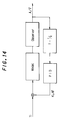
- the air-fuel ratios of the individual cylinders can, as shown in Figure 14, be separately controlled by a PID controller or the like.
- the correction coefficient ⁇ depends on the sampling interval (delta T) as shown in Equation 2. Since the behavior of the air-fuel ratio is considered to be synchronous with the TDC crank position as mentioned before, the sampling will therefore be conducted depending on the crank angles. The sampling interval will accordingly depend on the engine speed and thus varies with the change of the engine speed.
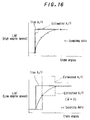
- the estimated air-fuel ratio (A/F) is close to the true air-fuel ratio (A/F) (illustrated by a solid line).
- the estimated air-fuel ratio (phantom line) is far from the true value (solid line), as shown in the bottom of Figure 16. The same will be applicable when the sensor output includes noise.
- the invention is based on this concept.
- the program begins at step S10 in which the engine speed is read and proceeds to step S12 in which the correction coefficient ⁇ is determined by retrieving a lookup table using the engine speed as address datum, and to step S14 in which the input air-fuel ratio (at the preceding cycle) is estimated using the correction coefficient ⁇ in accordance with Equation 4.
- Figure 15 shows the characteristic of the correction coefficient ⁇ .
- the correction coefficient ⁇ is set to be increased with increasing engine speed Ne such that the sampling interval is constant over almost entire range engine speed.
- the correction coefficient ⁇ is set to be zero at or below a predetermined engine speed such as 1000 rpm during idling.
- a predetermined engine speed such as 1000 rpm during idling.
- the estimated value has not be adjusted for the detection delay and hence is not equal to the true air-fuel ratio (solid line in Figure 16).
- estimation error decreases to a great extent when comparing with the value illustrated by a phantom line that would otherwise be obtained through estimation.
- the correction coefficient ⁇ is prepared in advance as a table look-up, the calculation period can therefore be reduced, enhancing estimation accuracy at a high engine speed. Furthermore, when the estimated air-fuel ratio adjusted for the sensor detection response delay is input to the second model describing the behavior of the exhaust system and the observer, the air-fuel ratios at the individual cylinders can accordingly be obtained with highly accuracy. And, it becomes possible to improve the control accuracy if the estimated values are used for an air-fuel ratio feedback control.
- the invention is not limited to this arrangement and can instead be configured to have air-fuel ratio sensors (LAF sensors) disposed in the exhaust system in a number equal to the number of cylinders and so as to detect the air-fuel ratios in the individual cylinders based on the outputs of the individual sensors.
- LAF sensors air-fuel ratio sensors
Landscapes
- Engineering & Computer Science (AREA)
- Chemical & Material Sciences (AREA)
- Combustion & Propulsion (AREA)
- Mechanical Engineering (AREA)
- General Engineering & Computer Science (AREA)
- Electrical Control Of Air Or Fuel Supplied To Internal-Combustion Engine (AREA)
- Combined Controls Of Internal Combustion Engines (AREA)
- Testing Of Engines (AREA)
Applications Claiming Priority (2)
| Application Number | Priority Date | Filing Date | Title |
|---|---|---|---|
| JP251140/93 | 1993-09-13 | ||
| JP5251140A JPH0783097A (ja) | 1993-09-13 | 1993-09-13 | 内燃機関の空燃比検出方法 |
Publications (2)
| Publication Number | Publication Date |
|---|---|
| EP0643211A1 true EP0643211A1 (fr) | 1995-03-15 |
| EP0643211B1 EP0643211B1 (fr) | 1998-01-07 |
Family
ID=17218273
Family Applications (1)
| Application Number | Title | Priority Date | Filing Date |
|---|---|---|---|
| EP94114307A Expired - Lifetime EP0643211B1 (fr) | 1993-09-13 | 1994-09-12 | Calculateur du rapport air-carburant pour un moteur à combustion interne |
Country Status (4)
| Country | Link |
|---|---|
| US (1) | US5569847A (fr) |
| EP (1) | EP0643211B1 (fr) |
| JP (1) | JPH0783097A (fr) |
| DE (1) | DE69407701T2 (fr) |
Cited By (6)
| Publication number | Priority date | Publication date | Assignee | Title |
|---|---|---|---|---|
| FR2733796A1 (fr) * | 1995-05-03 | 1996-11-08 | Siemens Ag | Procede de parametrage d'un regulateur lambda lineaire pour un moteur a combustion interne |
| FR2749350A1 (fr) * | 1996-06-03 | 1997-12-05 | Renault | Systeme de regulation de la richesse par mode de glissement |
| FR2749613A1 (fr) * | 1996-06-11 | 1997-12-12 | Renault | Systeme de regulation de la richesse dans un moteur a combustion interne |
| WO2009007343A1 (fr) * | 2007-07-10 | 2009-01-15 | Continental Automotive Gmbh | Procédé de détermination des paramètres de réglage d'un dispositif de réglage et dispositif de réglage fonctionnant selon ce procédé |
| WO2013079839A1 (fr) | 2011-11-28 | 2013-06-06 | Peugeot Citroen Automobiles Sa | Procede et dispositif permettant d'estimer en continu la richesse cylindre d'un moteur |
| EP2650516A1 (fr) | 2012-04-11 | 2013-10-16 | Peugeot Citroën Automobiles Sa | Procédé d'estimation de la richesse dans un moteur à combustion de véhicule automobile |
Families Citing this family (9)
| Publication number | Priority date | Publication date | Assignee | Title |
|---|---|---|---|---|
| WO1995034753A1 (fr) * | 1994-06-13 | 1995-12-21 | Hitachi, Ltd. | Dispositif et procede de mesure d'un debit d'air |
| US5865168A (en) | 1997-03-14 | 1999-02-02 | Nellcor Puritan Bennett Incorporated | System and method for transient response and accuracy enhancement for sensors with known transfer characteristics |
| DE19804985C1 (de) * | 1998-02-07 | 1999-05-06 | Bosch Gmbh Robert | Anordnung und Verfahren zur Abgasuntersuchung für Verbrennungsmotoren und Verwendung des Verfahrens |
| JP2003240620A (ja) * | 2002-02-20 | 2003-08-27 | Hitachi Ltd | 気体流量測定装置 |
| FR2867232B1 (fr) * | 2004-03-05 | 2006-05-05 | Inst Francais Du Petrole | Methode d'estimation de la richesse en carburant dans un cylindre d'un moteur a combustion |
| JP4424242B2 (ja) * | 2005-03-30 | 2010-03-03 | トヨタ自動車株式会社 | 内燃機関の混合気状態推定装置、及びエミッション発生量推定装置 |
| CN102132025B (zh) * | 2008-11-19 | 2014-09-10 | 丰田自动车株式会社 | 内燃机控制装置 |
| JP4924646B2 (ja) * | 2009-03-31 | 2012-04-25 | 株式会社デンソー | 内燃機関の排気浄化装置 |
| CN113090397B (zh) * | 2021-04-01 | 2023-07-04 | 联合汽车电子有限公司 | 发动机混合气控制系统参数识别方法及可读存储介质 |
Citations (3)
| Publication number | Priority date | Publication date | Assignee | Title |
|---|---|---|---|---|
| US4884548A (en) * | 1987-11-10 | 1989-12-05 | Fuji Jukogyo Kabushiki Kaisha | Fuel injection control system for an automotive engine |
| EP0546579A1 (fr) * | 1991-12-13 | 1993-06-16 | MAGNETI MARELLI S.p.A. | Système d'alimentation en carburant par injection électronique |
| EP0553570A2 (fr) * | 1991-12-27 | 1993-08-04 | Honda Giken Kogyo Kabushiki Kaisha | Méthode de détection et de contrôle du rapport air/carburant dans un moteur à combustion interne |
Family Cites Families (5)
| Publication number | Priority date | Publication date | Assignee | Title |
|---|---|---|---|---|
| JPS588238A (ja) * | 1981-07-06 | 1983-01-18 | Toyota Motor Corp | 燃料噴射式エンジンの燃料噴射量制御方法 |
| JPS59101562A (ja) * | 1982-11-30 | 1984-06-12 | Mazda Motor Corp | 多気筒エンジンの空燃比制御装置 |
| JP2512787B2 (ja) * | 1988-07-29 | 1996-07-03 | 株式会社日立製作所 | 内燃機関のスロットル開度制御装置 |
| JP3065127B2 (ja) * | 1991-06-14 | 2000-07-12 | 本田技研工業株式会社 | 酸素濃度検出装置 |
| JP2717744B2 (ja) * | 1991-12-27 | 1998-02-25 | 本田技研工業株式会社 | 内燃機関の空燃比検出及び制御方法 |
-
1993
- 1993-09-13 JP JP5251140A patent/JPH0783097A/ja active Pending
-
1994
- 1994-09-12 EP EP94114307A patent/EP0643211B1/fr not_active Expired - Lifetime
- 1994-09-12 DE DE69407701T patent/DE69407701T2/de not_active Expired - Lifetime
-
1995
- 1995-08-22 US US08/517,855 patent/US5569847A/en not_active Expired - Lifetime
Patent Citations (3)
| Publication number | Priority date | Publication date | Assignee | Title |
|---|---|---|---|---|
| US4884548A (en) * | 1987-11-10 | 1989-12-05 | Fuji Jukogyo Kabushiki Kaisha | Fuel injection control system for an automotive engine |
| EP0546579A1 (fr) * | 1991-12-13 | 1993-06-16 | MAGNETI MARELLI S.p.A. | Système d'alimentation en carburant par injection électronique |
| EP0553570A2 (fr) * | 1991-12-27 | 1993-08-04 | Honda Giken Kogyo Kabushiki Kaisha | Méthode de détection et de contrôle du rapport air/carburant dans un moteur à combustion interne |
Cited By (7)
| Publication number | Priority date | Publication date | Assignee | Title |
|---|---|---|---|---|
| FR2733796A1 (fr) * | 1995-05-03 | 1996-11-08 | Siemens Ag | Procede de parametrage d'un regulateur lambda lineaire pour un moteur a combustion interne |
| FR2749350A1 (fr) * | 1996-06-03 | 1997-12-05 | Renault | Systeme de regulation de la richesse par mode de glissement |
| FR2749613A1 (fr) * | 1996-06-11 | 1997-12-12 | Renault | Systeme de regulation de la richesse dans un moteur a combustion interne |
| WO1997047868A1 (fr) * | 1996-06-11 | 1997-12-18 | Renault | Systeme de regulation de la richesse dans un moteur a combustion interne |
| WO2009007343A1 (fr) * | 2007-07-10 | 2009-01-15 | Continental Automotive Gmbh | Procédé de détermination des paramètres de réglage d'un dispositif de réglage et dispositif de réglage fonctionnant selon ce procédé |
| WO2013079839A1 (fr) | 2011-11-28 | 2013-06-06 | Peugeot Citroen Automobiles Sa | Procede et dispositif permettant d'estimer en continu la richesse cylindre d'un moteur |
| EP2650516A1 (fr) | 2012-04-11 | 2013-10-16 | Peugeot Citroën Automobiles Sa | Procédé d'estimation de la richesse dans un moteur à combustion de véhicule automobile |
Also Published As
| Publication number | Publication date |
|---|---|
| JPH0783097A (ja) | 1995-03-28 |
| DE69407701D1 (de) | 1998-02-12 |
| US5569847A (en) | 1996-10-29 |
| EP0643211B1 (fr) | 1998-01-07 |
| DE69407701T2 (de) | 1998-04-16 |
Similar Documents
| Publication | Publication Date | Title |
|---|---|---|
| US5531208A (en) | Air-fuel ratio feedback control system for internal combustion engine | |
| US5524598A (en) | Method for detecting and controlling air-fuel ratio in internal combustion engine | |
| EP0688945B1 (fr) | Système pour détecter le rapport air-carburant d'un moteur à combustion interne multicylindre | |
| US5548514A (en) | Air/fuel ratio estimation system for internal combustion engine | |
| US5566071A (en) | Air/fuel ratio estimation system for internal combustion engine | |
| US5209214A (en) | Air fuel ratio control apparatus for engine | |
| US5462037A (en) | A/F ratio estimator for multicylinder internal combustion engine | |
| EP0582085A2 (fr) | Système de commande de dosage de carburant et méthode d'estimation de l'écoulement d'air dans un cylindre pour moteur à combustion interne | |
| US5569847A (en) | Air-fuel ratio estimator for internal combustion engine | |
| EP0677651A2 (fr) | Système d'estimation du taux de recirculation de gaz d'échappement pour moteur à combustion interne | |
| JPH05180040A (ja) | 内燃機関の空燃比検出及び制御方法 | |
| US6397830B1 (en) | Air-fuel ratio control system and method using control model of engine | |
| EP0670421B1 (fr) | Système de détection de panne pour moteur à combustion interne | |
| US5058550A (en) | Method for determining the control values of a multicylinder internal combustion engine and apparatus therefor | |
| US5540209A (en) | Air-fuel ratio detection system for internal combustion engine | |
| US5765530A (en) | Method of controlling ignition timing of internal combustion engine and apparatus therefore | |
| US7287525B2 (en) | Method of feedforward controlling a multi-cylinder internal combustion engine and associated feedforward fuel injection control system | |
| EP0431627B1 (fr) | Procédé et appareil adaptatif de commande de rapport air/carburant dans un moteur à combustion interne | |
| EP0156356B1 (fr) | Méthode de contrôle de l'alimentation en carburant d'un moteur à combustion interne | |
| US4718388A (en) | Method of controlling operating amounts of operation control means for an internal combustion engine | |
| US4858581A (en) | Air-fuel ratio feedback control method for internal combustion engines | |
| JP2576184B2 (ja) | 内燃機関の燃料噴射量制御装置 | |
| JPH077563Y2 (ja) | 内燃機関の電子制御燃料噴射装置 | |
| JPH09203343A (ja) | 内燃機関の空燃比検出装置 | |
| JPH0758052B2 (ja) | 内燃機関の電子制御燃料噴射装置 |
Legal Events
| Date | Code | Title | Description |
|---|---|---|---|
| PUAI | Public reference made under article 153(3) epc to a published international application that has entered the european phase |
Free format text: ORIGINAL CODE: 0009012 |
|
| AK | Designated contracting states |
Kind code of ref document: A1 Designated state(s): DE FR GB |
|
| 17P | Request for examination filed |
Effective date: 19950727 |
|
| 17Q | First examination report despatched |
Effective date: 19961108 |
|
| GRAG | Despatch of communication of intention to grant |
Free format text: ORIGINAL CODE: EPIDOS AGRA |
|
| GRAG | Despatch of communication of intention to grant |
Free format text: ORIGINAL CODE: EPIDOS AGRA |
|
| GRAH | Despatch of communication of intention to grant a patent |
Free format text: ORIGINAL CODE: EPIDOS IGRA |
|
| GRAH | Despatch of communication of intention to grant a patent |
Free format text: ORIGINAL CODE: EPIDOS IGRA |
|
| GRAA | (expected) grant |
Free format text: ORIGINAL CODE: 0009210 |
|
| AK | Designated contracting states |
Kind code of ref document: B1 Designated state(s): DE FR GB |
|
| REF | Corresponds to: |
Ref document number: 69407701 Country of ref document: DE Date of ref document: 19980212 |
|
| ET | Fr: translation filed | ||
| PLBE | No opposition filed within time limit |
Free format text: ORIGINAL CODE: 0009261 |
|
| STAA | Information on the status of an ep patent application or granted ep patent |
Free format text: STATUS: NO OPPOSITION FILED WITHIN TIME LIMIT |
|
| 26N | No opposition filed | ||
| REG | Reference to a national code |
Ref country code: GB Ref legal event code: IF02 |
|
| PGFP | Annual fee paid to national office [announced via postgrant information from national office to epo] |
Ref country code: GB Payment date: 20070912 Year of fee payment: 14 |
|
| PGFP | Annual fee paid to national office [announced via postgrant information from national office to epo] |
Ref country code: FR Payment date: 20070914 Year of fee payment: 14 |
|
| GBPC | Gb: european patent ceased through non-payment of renewal fee |
Effective date: 20080912 |
|
| REG | Reference to a national code |
Ref country code: FR Ref legal event code: ST Effective date: 20090529 |
|
| PG25 | Lapsed in a contracting state [announced via postgrant information from national office to epo] |
Ref country code: FR Free format text: LAPSE BECAUSE OF NON-PAYMENT OF DUE FEES Effective date: 20080930 |
|
| PG25 | Lapsed in a contracting state [announced via postgrant information from national office to epo] |
Ref country code: GB Free format text: LAPSE BECAUSE OF NON-PAYMENT OF DUE FEES Effective date: 20080912 |
|
| PGFP | Annual fee paid to national office [announced via postgrant information from national office to epo] |
Ref country code: DE Payment date: 20090910 Year of fee payment: 16 |
|
| REG | Reference to a national code |
Ref country code: DE Ref legal event code: R119 Ref document number: 69407701 Country of ref document: DE Effective date: 20110401 |
|
| PG25 | Lapsed in a contracting state [announced via postgrant information from national office to epo] |
Ref country code: DE Free format text: LAPSE BECAUSE OF NON-PAYMENT OF DUE FEES Effective date: 20110401 |