EP0643285A2 - Système de mesure de la position absolue de l'échelle mobile et périodique d'un codeur incrémental - Google Patents
Système de mesure de la position absolue de l'échelle mobile et périodique d'un codeur incrémental Download PDFInfo
- Publication number
- EP0643285A2 EP0643285A2 EP94111433A EP94111433A EP0643285A2 EP 0643285 A2 EP0643285 A2 EP 0643285A2 EP 94111433 A EP94111433 A EP 94111433A EP 94111433 A EP94111433 A EP 94111433A EP 0643285 A2 EP0643285 A2 EP 0643285A2
- Authority
- EP
- European Patent Office
- Prior art keywords
- measurement signals
- absolute position
- output
- evaluation unit
- measuring
- Prior art date
- Legal status (The legal status is an assumption and is not a legal conclusion. Google has not performed a legal analysis and makes no representation as to the accuracy of the status listed.)
- Granted
Links
- 230000000737 periodic effect Effects 0.000 title abstract 2
- 238000005259 measurement Methods 0.000 claims abstract description 56
- 238000000034 method Methods 0.000 claims abstract description 42
- 238000012937 correction Methods 0.000 claims abstract description 7
- 238000011156 evaluation Methods 0.000 claims description 30
- 238000005457 optimization Methods 0.000 claims description 17
- 230000006978 adaptation Effects 0.000 claims description 15
- 238000004364 calculation method Methods 0.000 claims description 13
- 230000003044 adaptive effect Effects 0.000 claims description 11
- 230000035945 sensitivity Effects 0.000 claims description 3
- 238000010206 sensitivity analysis Methods 0.000 claims description 3
- 230000009466 transformation Effects 0.000 claims description 2
- 238000013178 mathematical model Methods 0.000 claims 1
- 238000000844 transformation Methods 0.000 claims 1
- 238000010586 diagram Methods 0.000 description 2
- 238000006073 displacement reaction Methods 0.000 description 2
- 230000010354 integration Effects 0.000 description 2
- 230000005540 biological transmission Effects 0.000 description 1
- 230000015572 biosynthetic process Effects 0.000 description 1
- 230000001419 dependent effect Effects 0.000 description 1
- 238000009826 distribution Methods 0.000 description 1
- 230000000694 effects Effects 0.000 description 1
- 238000004519 manufacturing process Methods 0.000 description 1
- 239000011159 matrix material Substances 0.000 description 1
- 238000012544 monitoring process Methods 0.000 description 1
- 230000003287 optical effect Effects 0.000 description 1
- 238000007493 shaping process Methods 0.000 description 1
- 238000004088 simulation Methods 0.000 description 1
- 230000009897 systematic effect Effects 0.000 description 1
- 238000012360 testing method Methods 0.000 description 1
- 238000004804 winding Methods 0.000 description 1
Images
Classifications
-
- G—PHYSICS
- G01—MEASURING; TESTING
- G01D—MEASURING NOT SPECIALLY ADAPTED FOR A SPECIFIC VARIABLE; ARRANGEMENTS FOR MEASURING TWO OR MORE VARIABLES NOT COVERED IN A SINGLE OTHER SUBCLASS; TARIFF METERING APPARATUS; MEASURING OR TESTING NOT OTHERWISE PROVIDED FOR
- G01D5/00—Mechanical means for transferring the output of a sensing member; Means for converting the output of a sensing member to another variable where the form or nature of the sensing member does not constrain the means for converting; Transducers not specially adapted for a specific variable
- G01D5/12—Mechanical means for transferring the output of a sensing member; Means for converting the output of a sensing member to another variable where the form or nature of the sensing member does not constrain the means for converting; Transducers not specially adapted for a specific variable using electric or magnetic means
- G01D5/244—Mechanical means for transferring the output of a sensing member; Means for converting the output of a sensing member to another variable where the form or nature of the sensing member does not constrain the means for converting; Transducers not specially adapted for a specific variable using electric or magnetic means influencing characteristics of pulses or pulse trains; generating pulses or pulse trains
- G01D5/24471—Error correction
- G01D5/24495—Error correction using previous values
-
- G—PHYSICS
- G01—MEASURING; TESTING
- G01P—MEASURING LINEAR OR ANGULAR SPEED, ACCELERATION, DECELERATION, OR SHOCK; INDICATING PRESENCE, ABSENCE, OR DIRECTION, OF MOVEMENT
- G01P13/00—Indicating or recording presence, absence, or direction, of movement
- G01P13/02—Indicating direction only, e.g. by weather vane
- G01P13/04—Indicating positive or negative direction of a linear movement or clockwise or anti-clockwise direction of a rotational movement
Definitions
- the invention relates to a system, in particular a method and / or a device, for measuring the absolute position of the movable, cyclical graduation mark carrier of an incremental position transmitter within and / or with respect to one of its graduation segments, which are periodically formed by the preferably equidistant division marks on the carrier and / or are limited, the measurement being carried out with two scanning elements which are arranged in a stationary manner with respect to the carrier and respond to the graduation marks and which are approximately one quarter of the division segment length apart, so that they generate approximately two phase-shifted measurement signals such as sine and cosine. These can then be evaluated for position determination using an arctangent function.
- mark divisions are scanned, which can be formed on a rotatable, rotationally symmetrical or linear, longitudinally displaceable division mark carrier.
- the division can, as is known per se, be realized by magnetic and non-magnetic, optically transparent and opaque segments or by teeth and tooth gaps (on a toothed wheel or a toothed rack), which alternately follow one another.
- a sequence of current or voltage pulses is obtained, the number (increments) of which corresponds to a rough angular or longitudinal position value.
- the poor signal quality of the sine and cosine measurement signals of the known sensors according to the cyclical-absolute measurement principle results in errors in the measurement signal evaluation.
- this is due to an uneven, i.e. Distribution of the segments or periods with manufacturing tolerances over the length or circumference of the division mark carrier, to small differences in the width of the line marks on the optical (division carrier) disc or to centering or guiding errors of the brand carrier.
- a machine equipped with a generic position sensor warm there may be eccentric displacements of the division mark carrier, which falsifies the signal evaluation or position determination.
- a precise position control with high-resolution position sensors is essential, especially in the printing press area.
- the problem on which the invention is based is in the case of the measuring system mentioned at the outset with physical or structurally constant graduation to achieve a refined resolution, especially the absolute position between two graduation marks or within a graduation segment.
- the evaluation is corrected for the above-mentioned disturbances and inaccuracies in the position transmitter by generating a parameter vector which identifies the measurement process of the position transmitter and whose values are used to correct the evaluation. wherein the parameter vector is constantly redetermined during the measurement operation according to predetermined optimization criteria.
- a measuring device of the type mentioned at the outset which has a computing system which has an evaluation unit which receives the measuring signals on the basis of the arctangent function, the computing system being provided with a filter and / or adaptation unit on the input side parallel to the evaluation unit with the measurement signals and on the output side to the evaluation unit for the transmission of adaptive measurement signals which are generated according to an adaptation rule implemented in the adaptation unit depending on the measurement signals, and in which the adaptive measurement signals are linked to the measurement signals in accordance with a correction calculation rule.
- the correction of the measurement errors mentioned at the outset is achieved in that a parameter or adaptive measurement signal vector is generated via an adaptation law, which vector is continuously compared in the current measurement mode. This vector is then used to correct the evaluation of the sine and cosine measurement signals.
- This correction is related to the division (for example, related to a tooth) and / or related to the graduation incarnation (eg gearwheel) in order to correct, above all, division errors in the measurement signal evaluation.
- the optimization criteria include an adaptation rule, which is structured in particular according to the method of least squares and / or a gradient method, optionally with sensitivity analysis; This allows the parameter vector to be compared on-line with the current measuring operation or to be adapted to the current measuring process, especially the individual division segments.
- Optimization methods or algorithms such as gradient methods, systematic search methods or random search methods as well as the assessment of the dynamic behavior of real systems by means of parameter sensitivity analysis are known per se (cf. "adaptive control systems", Heinz Unbehauen, study or lecture at the University of Stuttgart, 1971/1975, especially pages 15 - 26).
- a parameterized, algorithmic model of the measurement process is created in parallel with the ongoing measurement operation and is continuously updated on the basis of the corrected position values and / or the parameter adaptive measurement signal vector. Its output values can then be compared for optimization with the measurement signals that can be picked up from the scanning elements.
- Identification methods with adaptive models, in particular parallel comparison models with a structure that is as similar as possible to the system to be examined, are known per se (cf. Unbehauen aaO, in particular page 28ff.). This also applies to the method of least squares (see Unbehauen aaO).
- the measurement process or the real measurement signals or at least their fundamental waves can be identified and, if necessary, modeled by means of the mathematical definition of an ellipse or, in the special case of a circle, or the correspondingly optimized parameter vector can be set up.
- the comparison model is based on a general ellipse, which is arbitrary with respect to the coordinate cross in the Cartesian coordinate system and is described by model equations or the corresponding parameter set.
- the adaptation of the parameter set corresponding to each division mark or division segment can be expediently operated as a background process at a slower speed in the measuring device according to the invention in the computer system. To put it on or initialize it the number of division marks or the divisions per unit of length or angle must be entered into the computing system.
- the invention is not restricted to use with incremental position sensors.
- well-known resolvers / resolvers can be used with the same effect: Because the resolver has two windings offset by 90 ° as sensing elements in the stator and rotor, so that there are also two sine and cosine-like output signals, which depend on the angular position of the Unhook the rotor as a division mark carrier.
- the carrier frequency of the resolver must still be eliminated.
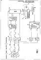
- a disc 1 which is attached to a shaft (not shown) in a rotationally rigid manner, is set in rotation. It has lines distributed uniformly on its circumference, which form division marks 2 and each delimit a division segment 3. Due to the rotation of the disk 1, these move past, for example, optically functioning scanning heads 4. Since the distance between two of these is approximately a quarter of the distance between two graduation marks on the disk or graduation mark carrier 1, measurement signals sin, cos result at their outputs, which are mutually dependent on the accuracy of the graduation on the graduation mark carrier 1 and / or the distance between the scanning heads 4 are in a sine / cosine-like phase relationship.
- a pulse shaping stage 5 converts these signals into corresponding square-wave pulses, so that they can be further processed digitally, in particular in a counter module 6.
- An analog / digital converter stage 7 converts the two sine and cosine-like measurement signals into a binary value x, y, which can be processed according to equation (2) above as a complex number and / or as ellipse coordinates with respect to a Cartesian coordinate system.
- These (digitized) measuring signals x, y are fed to a measuring and evaluating device 8 designed according to the invention, which has a real absolute position value ⁇ * with respect to the two division marks 2 of a division segment 3 (see FIG. 6) in one of disturbances and inaccuracies corrected adaptively adjusted absolute position value ⁇ . This is then combined with the result of the division mark counter 6, which has incremented its counter reading in accordance with the division marks that occurred during the rotation, to form the total absolute position value.
- a computing unit 9 which has two registers 10, 11 and a module 12 for consistency monitoring. This controls the consistent or positionally correct pushing together of the binary value representing the absolute value ⁇ in the first register 10 with the binary value representing the enumerated division segments or division marks in the second register 11.
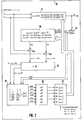
- the measuring and evaluation device 8 is provided with a computing system 13 which has an evaluation unit 14 for the measurement signals x, y which operates on the basis of the arctus tangent.
- evaluation unit 14 At the output, evaluation unit 14 generates the corrected absolute position signal (or a corresponding binary value) ⁇ .
- the measurement signals are also compared in the computing system 13 in two summing or comparison points 15x, 15y, each with an output value Xm, Ym of a comparison model 16, or the model values are subtracted therefrom.
- the resulting deviations x, y are further processed in an amplifier stage 17 by multiplication by the constant K in error values Ex, Ey.
- the computing system 13 also has an optimization computing module 18 to which the error signals Ex, Ey are fed. Furthermore, this module 18 is supplied with the outputs of a sine and cosine function generator 19 which calculates its sine and cosine from the corrected absolute position signal ⁇ .
- Ey sensitivity functions are implemented, which are an adaptation law Realize according to the gradient method and the method of least squares (cf. Unbehauen aaO) in connection with the difference formation 15x, 15y.
- a differential parameter vector dX0, dY0, dXc, dXd, dYc, dYd is first created.
- the differential parameter signals dXo - dYd are integrated in the integration stage 21. If a digital computer with numerical calculation methods is used instead of an analog computer, then the output signals dX0 ... dYd of the optimization calculation module 18 represent difference signals which have an approximately equivalent summation stage 21 can be added up.
- the adapted parameter vector or set X0, Y0, Xc, Xd, Yc, Yd is then present at the output of this integrating or summing stage 21 and is supplied to both the evaluation unit 14 and the comparison model 16 as input parameters.
- the outputs of the sine and cosine function generator 19 with the corresponding function values of the sine and cosine of the corrected absolute position ⁇ are also fed directly to the comparison model 16.
- the comparison model 16 processes the parameter vector or set X0 ... Yd and the sine and cosine of the corrected absolute position ⁇ in accordance with the above equations (16) (real part) and (17) (imaginary part).
- the real and imaginary parts X m , Y m are then fed to the respective comparison points 15X, 15Y with a negative sign.
- the computing process for the comparison model 16 can run in the computing system as part of a slower background process.
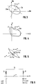
- the pair of measurement signals X, Y determines the absolute position within a division segment 3 between two division marks 2, which is present as an imprecise or disturbed absolute position signal ⁇ *.
- the division segment 3 forms a period or a cycle. The aim is now to produce a fine subdivision between the two division marks 2 for the purpose of higher resolution, without having to constructively divide the division marks 2.
- This irregularly curved curve Z contains, in particular, the following disturbances or inaccuracies: displacement from the coordinate origin or zero point of the Cartesian coordinate system, which can be based, for example, on an electrical offset; Distortion of the circle, which is ideally present, due to the fluctuating amplitude ratio of the measurement signals from the two scanning heads 4; Fluctuations and disturbances in the mutual angular or phase relationship of the two measurement signals X, Y from the scanning heads, which leads to the rotation of the ellipse or its axes relative to the coordinate system. These falsifications of measured values mostly occur in combination.
- the strategy now consists in interpreting the measurement signal Z in the comparison model 16 in such a way that the above-mentioned distortions are reduced to an ellipse which may be rotated and offset in the Cartesian coordinate system due to the above interference and inaccuracies.
- the general lying ellipse which can be described in complex form Z m and which corresponds best to the measurement signal Z according to equation (2) above is now sought. This is illustrated in FIG.
- the parameter set x o ... Y d created after integration 21 then serves on the one hand to update the comparison model 16.
- the generally lying ellipse Z m according to FIG. 3 is corrected by the correction calculation rule of the evaluation unit 14 in the context of the arc tangent transformed a circle of origin.
- Ellipse transformation equations are generally known (cf. Bronstein, op. Cit., Pages 182, 183).
- the parameters x o and y o represent the parallel or zero point shift.
- the absolute position signal ⁇ corrected in this way then forms a highly precise, highly current measurement signal which can be used, for example, as a position control signal in direct drive printing presses.
- a multiplication of division has arisen, so to speak, without the number of division marks 2 being increased.
- the absolute position signal ⁇ divides the ellipse curve or the division segment 3 between the two division marks 2.
Landscapes
- Physics & Mathematics (AREA)
- General Physics & Mathematics (AREA)
- Transmission And Conversion Of Sensor Element Output (AREA)
- Length Measuring Devices With Unspecified Measuring Means (AREA)
- Optical Transform (AREA)
Applications Claiming Priority (2)
| Application Number | Priority Date | Filing Date | Title |
|---|---|---|---|
| DE4331151 | 1993-09-14 | ||
| DE4331151A DE4331151C2 (de) | 1993-09-14 | 1993-09-14 | System zur Messung der Absolutposition des beweglichen, zyklischen Teilungsmarken-Trägers eines inkrementalen Positionsgebers |
Publications (3)
| Publication Number | Publication Date |
|---|---|
| EP0643285A2 true EP0643285A2 (fr) | 1995-03-15 |
| EP0643285A3 EP0643285A3 (fr) | 1997-07-30 |
| EP0643285B1 EP0643285B1 (fr) | 2000-05-10 |
Family
ID=6497670
Family Applications (1)
| Application Number | Title | Priority Date | Filing Date |
|---|---|---|---|
| EP94111433A Expired - Lifetime EP0643285B1 (fr) | 1993-09-14 | 1994-07-22 | Système de mesure de la position absolue de l'échelle mobile et périodique d'un codeur incrémental |
Country Status (6)
| Country | Link |
|---|---|
| US (1) | US5612906A (fr) |
| EP (1) | EP0643285B1 (fr) |
| JP (1) | JPH07174586A (fr) |
| AT (1) | ATE192845T1 (fr) |
| DE (2) | DE4331151C2 (fr) |
| ES (1) | ES2145076T3 (fr) |
Cited By (7)
| Publication number | Priority date | Publication date | Assignee | Title |
|---|---|---|---|---|
| EP0669517A3 (fr) * | 1994-02-18 | 1996-01-31 | Canon Kk | Elaborateur et capteur de déplacement. |
| GB2286679B (en) * | 1994-01-28 | 1998-07-22 | Mitsubishi Electric Corp | Absolute position detection apparatus and error compensation methods therefor |
| WO2000079220A1 (fr) * | 1999-06-22 | 2000-12-28 | Robert Bosch Gmbh | Procede de compensation de decalage de capteurs de mesure d'angles |
| EP1271093A3 (fr) * | 2001-06-27 | 2006-11-22 | Philips Intellectual Property & Standards GmbH | Ajustement d'un palpeur d'angle magnéto-résistif |
| DE102005060989B3 (de) * | 2005-12-20 | 2007-05-10 | Siemens Ag | System zum Ermitteln eines aktuellen absoluten Positionswerts |
| DE19712622C5 (de) * | 1997-03-26 | 2010-07-15 | Dr. Johannes Heidenhain Gmbh | Anordnung und Verfahren zur automatischen Korrektur fehlerbehafteter Abtastsignale inkrementaler Positionsmeßeinrichtungen |
| CN102721394A (zh) * | 2012-06-29 | 2012-10-10 | 北京经纬恒润科技有限公司 | 一种增量式编码器检测系统 |
Families Citing this family (34)
| Publication number | Priority date | Publication date | Assignee | Title |
|---|---|---|---|---|
| WO1998021553A1 (fr) * | 1996-11-11 | 1998-05-22 | Fanuc Ltd. | Circuit d'interpolation de codeur |
| DE19720968A1 (de) * | 1997-05-17 | 1998-11-19 | Ingolf Dr Weingaertner | Verfahren zur Ermittlung der Fehler einer Winkelteilung aus der Winkelteilungsdifferenz, bestimmt aus der Differenz zweier Winkelpositionen mit jeweils konstantem Winkelabstand |
| AT2385U1 (de) * | 1997-09-09 | 1998-09-25 | Amo Automatisierung Messtechni | Winkelmesssystem |
| DE19817356A1 (de) * | 1998-04-18 | 1999-10-21 | Bosch Gmbh Robert | Winkelgeber und Verfahren zur Winkelbestimmung |
| DE19831960A1 (de) * | 1998-07-16 | 2000-01-20 | Itt Mfg Enterprises Inc | Wegsensor |
| DE19911822C1 (de) * | 1999-03-17 | 2000-08-24 | Brown & Sharpe Gmbh | Verfahren zur Korrektur von Interpolationsfehlern beim Ablesen von Inkrementalmaßstäben durch einen Positionsgeber |
| DE10066138B4 (de) * | 1999-03-30 | 2004-09-23 | Dr. Johannes Heidenhain Gmbh | Verfahren und Schaltungsanordnung zur Korrektur von periodischen Signalen eines inkrementalen Positionsmesssystems |
| DE10014056A1 (de) | 1999-03-30 | 2000-10-19 | Heidenhain Gmbh Dr Johannes | Verfahren und Schaltungsanordnung zur Korrektur von periodischen Signalen eines inkrementalen Positionsmessystems |
| DE19934478B4 (de) * | 1999-07-27 | 2007-12-27 | GEMAC-Gesellschaft für Mikroelektronikanwendung Chemnitz mbH | Digitale Interpolationseinrichtung |
| DE10034733B4 (de) * | 1999-08-02 | 2004-07-08 | Siemens Ag | Ermittlungsverfahren für ein Lagesignal und/oder für Korrekturwerte für Messsignale |
| DE19937737C2 (de) | 1999-08-10 | 2003-10-30 | Pilz Gmbh & Co | Vorrichtung zum sicheren Überwachen der Drehbewegung einer Welle |
| US6411081B1 (en) * | 2000-02-10 | 2002-06-25 | Siemens Ag | Linear position sensor using magnetic fields |
| US6556946B2 (en) | 2000-12-19 | 2003-04-29 | Caterpillar Inc | Linear position sensor |
| EP1245931A1 (fr) * | 2001-03-31 | 2002-10-02 | Leica Geosystems AG | Procédé pour l'étalonage d'un instrument de mesure |
| FI111033B (fi) | 2001-06-15 | 2003-05-15 | Metso Paper Inc | Menetelmä rullan tiheyden määrittämiseksi |
| DE10154153A1 (de) | 2001-11-03 | 2003-05-15 | Bosch Gmbh Robert | Achsenschnittverfahren und N-Punkte-Methode zum Offsetabgleich von Winkelsensoren |
| DE10233155A1 (de) * | 2002-07-22 | 2004-02-12 | Abb Patent Gmbh | Verfahren zur Korrektur systematischer Geometriefehler in einem Drehwinkelmessgerät |
| DE102004029815A1 (de) * | 2004-06-19 | 2006-01-05 | Robert Bosch Gmbh | Verfahren und Anordnung zur Korrektur eines winkel- und/oder abstandsmessenden Sensorsystems |
| DE102004033990B3 (de) | 2004-07-14 | 2006-04-13 | Siemens Ag | Auswerteverfahren für ein analoges Erstsignal und ein analoges Zweitsignal sowie hiermit korrespondierende Auswerteschaltung |
| DE102004038622B3 (de) * | 2004-08-09 | 2006-05-18 | Siemens Ag | Ermittlungsverfahren für eine tatsächliche Absolutlage eines relativ zu einem Grundelement bewegbaren Zusatzelements, korrespondierendes Erstellverfahren für eine Korrekturwerttabelle, korrespondierende Ermittlungseinrichtung und Speichereinrichtung, in der eine Korrekturwerttabelle hinterlegt ist |
| DE102004043448A1 (de) | 2004-09-06 | 2006-03-23 | Lenord, Bauer & Co. Gmbh | Verfahren zur elektronischen Kalibrierung mechanischer Fertigungstoleranzen von Positionssensoren |
| US7506280B2 (en) * | 2004-11-12 | 2009-03-17 | Tabtronics, Inc. | Magnetic winding and method of making same |
| JP4689435B2 (ja) * | 2004-12-16 | 2011-05-25 | アルプス電気株式会社 | 角度検出センサ |
| DE102005024879B4 (de) * | 2005-05-31 | 2018-12-06 | Infineon Technologies Ag | Verfahren zum Bestimmen von Restfehler-Kompensationsparametern für einen magnetoresistiven Winkelsensor und Verfahren zum Verringern eines Restwinkelfehlers bei einem magnetoresistiven Winkelsensor |
| CA2641407C (fr) * | 2006-02-03 | 2013-12-17 | California Linear Devices, Inc. | Systeme d'analyse de signal codeur pour mesure de position haute resolution |
| DE102006012074B4 (de) * | 2006-03-16 | 2015-11-05 | Robert Bosch Gmbh | Postionsmesseinrichtung mit Überwachungsvorrichtung |
| WO2007137625A1 (fr) * | 2006-06-01 | 2007-12-06 | Freescale Semiconductor, Inc. | Agencement de capteur sin-cos, circuit intégré sin-cos et procédé correspondant |
| CN100451558C (zh) * | 2006-11-10 | 2009-01-14 | 重庆工学院 | 一种绝对式角位移传感器 |
| DE102007002221A1 (de) * | 2007-01-10 | 2008-07-17 | Paragon Ag | Wegsensoreinrichtung zur Erfassung des Weges bzw. der Position eines verstellbaren Bauteils und entsprechende Verfahren zur Weg- bzw. Positionserfassung |
| US8493572B2 (en) | 2010-05-05 | 2013-07-23 | Mitutoyo Corporation | Optical encoder having contamination and defect resistant signal processing |
| DE102010023387B4 (de) * | 2010-06-10 | 2024-12-12 | Volkswagen Ag | Verfahren und Vorrichtung zur Kompensation eines Sensorfehlers |
| DE102010051873B4 (de) * | 2010-11-22 | 2013-03-14 | Ic-Haus Gmbh | Integrierte Schaltungsanordnung und Verfahren zur Signalüberwachung |
| EP2995910B1 (fr) | 2014-09-11 | 2016-11-16 | Baumüller Nürnberg GmbH | Système et procédé de mesure de position absolue |
| DE102017222508B4 (de) * | 2017-12-12 | 2022-02-17 | Carl Zeiss Industrielle Messtechnik Gmbh | Verfahren und Vorrichtung zur Korrektur von Messsystemabweichungen |
Citations (2)
| Publication number | Priority date | Publication date | Assignee | Title |
|---|---|---|---|---|
| DE4100666A1 (de) | 1990-11-07 | 1992-05-14 | Heidenhain Gmbh Dr Johannes | Vorrichtung zur unterteilung von analogen periodischen signalen |
| US5202842A (en) | 1989-11-29 | 1993-04-13 | Kabushiki Kaisha Okuma Tekkosho | Rotational position detecting device which compensates for eccentricity of rotating object |
Family Cites Families (3)
| Publication number | Priority date | Publication date | Assignee | Title |
|---|---|---|---|---|
| EP0450829B2 (fr) * | 1990-03-30 | 2002-09-04 | Texas Instruments Incorporated | Capteur intelligent et programmable |
| US5463393A (en) * | 1991-12-05 | 1995-10-31 | Acutronic Ag | Method and apparatus for correcting errors in an amplitude encoded signal |
| JPH06167354A (ja) * | 1992-11-27 | 1994-06-14 | Sony Magnescale Inc | スケールの内挿処理装置 |
-
1993
- 1993-09-14 DE DE4331151A patent/DE4331151C2/de not_active Expired - Lifetime
-
1994
- 1994-07-22 AT AT94111433T patent/ATE192845T1/de active
- 1994-07-22 DE DE59409336T patent/DE59409336D1/de not_active Expired - Lifetime
- 1994-07-22 EP EP94111433A patent/EP0643285B1/fr not_active Expired - Lifetime
- 1994-07-22 ES ES94111433T patent/ES2145076T3/es not_active Expired - Lifetime
- 1994-09-12 US US08/304,764 patent/US5612906A/en not_active Expired - Lifetime
- 1994-09-13 JP JP6218628A patent/JPH07174586A/ja active Pending
Patent Citations (2)
| Publication number | Priority date | Publication date | Assignee | Title |
|---|---|---|---|---|
| US5202842A (en) | 1989-11-29 | 1993-04-13 | Kabushiki Kaisha Okuma Tekkosho | Rotational position detecting device which compensates for eccentricity of rotating object |
| DE4100666A1 (de) | 1990-11-07 | 1992-05-14 | Heidenhain Gmbh Dr Johannes | Vorrichtung zur unterteilung von analogen periodischen signalen |
Non-Patent Citations (2)
| Title |
|---|
| ROLF-DIETER KLUG: "Echtzeitsimulation mechanischer Lastsysteme zur Prüfung elektrischer Servoantriebe", DISSERTATION AN DER TECHNISCHEN FAKULTÄT DER UNIVERSITÄT ERLANGEN-NÜRNBERG, 1992, pages 99 - 131 |
| SCHLIESSLICH WURDE, TM - TECHNISCHES MESSEN, vol. 12, 1992, pages 497 - 503 |
Cited By (9)
| Publication number | Priority date | Publication date | Assignee | Title |
|---|---|---|---|---|
| GB2286679B (en) * | 1994-01-28 | 1998-07-22 | Mitsubishi Electric Corp | Absolute position detection apparatus and error compensation methods therefor |
| EP0669517A3 (fr) * | 1994-02-18 | 1996-01-31 | Canon Kk | Elaborateur et capteur de déplacement. |
| US5625310A (en) * | 1994-02-18 | 1997-04-29 | Canon Kabushiki Kaisha | Signal processing apparatus and displacement detecting apparatus using the same |
| DE19712622C5 (de) * | 1997-03-26 | 2010-07-15 | Dr. Johannes Heidenhain Gmbh | Anordnung und Verfahren zur automatischen Korrektur fehlerbehafteter Abtastsignale inkrementaler Positionsmeßeinrichtungen |
| WO2000079220A1 (fr) * | 1999-06-22 | 2000-12-28 | Robert Bosch Gmbh | Procede de compensation de decalage de capteurs de mesure d'angles |
| US6496784B1 (en) | 1999-06-22 | 2002-12-17 | Robert Bosch Gmbh | Method for compensating the offset of angle sensors |
| EP1271093A3 (fr) * | 2001-06-27 | 2006-11-22 | Philips Intellectual Property & Standards GmbH | Ajustement d'un palpeur d'angle magnéto-résistif |
| DE102005060989B3 (de) * | 2005-12-20 | 2007-05-10 | Siemens Ag | System zum Ermitteln eines aktuellen absoluten Positionswerts |
| CN102721394A (zh) * | 2012-06-29 | 2012-10-10 | 北京经纬恒润科技有限公司 | 一种增量式编码器检测系统 |
Also Published As
| Publication number | Publication date |
|---|---|
| DE59409336D1 (de) | 2000-06-15 |
| EP0643285A3 (fr) | 1997-07-30 |
| ATE192845T1 (de) | 2000-05-15 |
| ES2145076T3 (es) | 2000-07-01 |
| JPH07174586A (ja) | 1995-07-14 |
| EP0643285B1 (fr) | 2000-05-10 |
| US5612906A (en) | 1997-03-18 |
| DE4331151A1 (de) | 1995-03-23 |
| DE4331151C2 (de) | 1997-05-22 |
Similar Documents
| Publication | Publication Date | Title |
|---|---|---|
| EP0643285B1 (fr) | Système de mesure de la position absolue de l'échelle mobile et périodique d'un codeur incrémental | |
| DE2617707C2 (de) | Vorrichtung zum Vermessen einer Oberfläche | |
| DE3880299T2 (de) | Verfahren zum Messen von Zahnradfehlern durch Abwälzen und Maschine dafür. | |
| DE69009091T2 (de) | Verfahren und Vorrichtung zur Signalverarbeitung. | |
| EP1001248A2 (fr) | Méthode de calibrage offset d'un palpeur d'angle magnéto-résistif | |
| DE112007001189T5 (de) | Verfahren und Einrichtung zur Verwendung in Echtzeit-Nanometer- und Sub-Nanometer-Positionsmessungen | |
| EP1271093A2 (fr) | Ajustement d'un palpeur d'angle magnéto-résistif | |
| DE10321210B4 (de) | Drehmoment-Messverfahren für eine Wellengetriebevorrichtung | |
| DE102017202217A1 (de) | Verfahren und Vorrichtung zur Korrektur eines Ausgangssignals einer Messeinrichtung | |
| DE3027089A1 (de) | Vorrichtung zum messen und korrigieren der lenkgeometrie von kraftfahrzeugen | |
| DE102013217216B4 (de) | Verfahren und Vorrichtung zur Fehlerermittlung und Fehlerkompensation eines inkrementellen Sensors | |
| DE102021005044B4 (de) | Messdatenprozessor, Positionsmessgerät und computerimplementiertes Verfahren | |
| EP0491749B1 (fr) | Dispositif de mesure de position absolue sur deux dimensions | |
| DE69427326T2 (de) | Verbesserte Positionssignale in optischen Drehmomentsensoren | |
| DE4317064A1 (de) | Positionsmeßvorrichtung | |
| EP3124920B1 (fr) | Dispositif de mesure de position et son procédé de fonctionnement | |
| DE102017222508B4 (de) | Verfahren und Vorrichtung zur Korrektur von Messsystemabweichungen | |
| WO2005008182A1 (fr) | Dispositif de mesure de position permettant la determination de positions angulaires ou de longueurs | |
| DE602004002240T2 (de) | Interpolationsverfahren für einen hochauflösenden optischen Winkelgeber und zugehöriger optischer Winkelgeber | |
| EP2295939B1 (fr) | Procédé de détermination de la valeur précise du positionnement d'un corps devant être surveillé | |
| EP2107343A2 (fr) | Dispositif de mesure d'angle pour un système émetteur rotatif | |
| DE60313479T2 (de) | Vorrichtung zur messung einer optischen weglängenveränderung | |
| EP0596535A2 (fr) | Méthode de mesure à haute résolution de positions linéaires et tournantes | |
| DE10247321B3 (de) | Verfahren zum Offsetabgleich einer Sensoranordnung zur Erfassung einer Bewegung oder eines Drehwinkels | |
| DE19915968A1 (de) | Anordnung zum Offsetabgleich zweier orthogonaler Sensorsignale |
Legal Events
| Date | Code | Title | Description |
|---|---|---|---|
| PUAI | Public reference made under article 153(3) epc to a published international application that has entered the european phase |
Free format text: ORIGINAL CODE: 0009012 |
|
| AK | Designated contracting states |
Kind code of ref document: A2 Designated state(s): AT CH DE ES FR GB IT LI |
|
| PUAL | Search report despatched |
Free format text: ORIGINAL CODE: 0009013 |
|
| AK | Designated contracting states |
Kind code of ref document: A3 Designated state(s): AT CH DE ES FR GB IT LI |
|
| 17P | Request for examination filed |
Effective date: 19971016 |
|
| 17Q | First examination report despatched |
Effective date: 19980326 |
|
| GRAG | Despatch of communication of intention to grant |
Free format text: ORIGINAL CODE: EPIDOS AGRA |
|
| RTI1 | Title (correction) |
Free format text: SYSTEM FOR MEASURING THE ABSOLUTE POSITION OF THE MOVABLE PERIODIC SCALE OF AN INCREMENTAL ENCODER |
|
| GRAG | Despatch of communication of intention to grant |
Free format text: ORIGINAL CODE: EPIDOS AGRA |
|
| GRAH | Despatch of communication of intention to grant a patent |
Free format text: ORIGINAL CODE: EPIDOS IGRA |
|
| GRAH | Despatch of communication of intention to grant a patent |
Free format text: ORIGINAL CODE: EPIDOS IGRA |
|
| GRAA | (expected) grant |
Free format text: ORIGINAL CODE: 0009210 |
|
| AK | Designated contracting states |
Kind code of ref document: B1 Designated state(s): AT CH DE ES FR GB IT LI |
|
| REF | Corresponds to: |
Ref document number: 192845 Country of ref document: AT Date of ref document: 20000515 Kind code of ref document: T |
|
| REG | Reference to a national code |
Ref country code: CH Ref legal event code: NV Representative=s name: ISLER & PEDRAZZINI AG Ref country code: CH Ref legal event code: EP |
|
| REF | Corresponds to: |
Ref document number: 59409336 Country of ref document: DE Date of ref document: 20000615 |
|
| REG | Reference to a national code |
Ref country code: ES Ref legal event code: FG2A Ref document number: 2145076 Country of ref document: ES Kind code of ref document: T3 |
|
| GBT | Gb: translation of ep patent filed (gb section 77(6)(a)/1977) |
Effective date: 20000608 |
|
| ITF | It: translation for a ep patent filed | ||
| ET | Fr: translation filed | ||
| PLBE | No opposition filed within time limit |
Free format text: ORIGINAL CODE: 0009261 |
|
| STAA | Information on the status of an ep patent application or granted ep patent |
Free format text: STATUS: NO OPPOSITION FILED WITHIN TIME LIMIT |
|
| 26N | No opposition filed | ||
| REG | Reference to a national code |
Ref country code: GB Ref legal event code: IF02 |
|
| PG25 | Lapsed in a contracting state [announced via postgrant information from national office to epo] |
Ref country code: IT Free format text: LAPSE BECAUSE OF NON-PAYMENT OF DUE FEES Effective date: 20050722 |
|
| PGFP | Annual fee paid to national office [announced via postgrant information from national office to epo] |
Ref country code: GB Payment date: 20060703 Year of fee payment: 13 |
|
| REG | Reference to a national code |
Ref country code: CH Ref legal event code: PCAR Free format text: ISLER & PEDRAZZINI AG;POSTFACH 1772;8027 ZUERICH (CH) |
|
| GBPC | Gb: european patent ceased through non-payment of renewal fee |
Effective date: 20070722 |
|
| PG25 | Lapsed in a contracting state [announced via postgrant information from national office to epo] |
Ref country code: GB Free format text: LAPSE BECAUSE OF NON-PAYMENT OF DUE FEES Effective date: 20070722 |
|
| PGRI | Patent reinstated in contracting state [announced from national office to epo] |
Ref country code: IT Effective date: 20091001 |
|
| PGFP | Annual fee paid to national office [announced via postgrant information from national office to epo] |
Ref country code: CH Payment date: 20110706 Year of fee payment: 18 |
|
| PGFP | Annual fee paid to national office [announced via postgrant information from national office to epo] |
Ref country code: DE Payment date: 20120921 Year of fee payment: 19 Ref country code: ES Payment date: 20120723 Year of fee payment: 19 Ref country code: FR Payment date: 20120803 Year of fee payment: 19 Ref country code: IT Payment date: 20120724 Year of fee payment: 19 |
|
| PGFP | Annual fee paid to national office [announced via postgrant information from national office to epo] |
Ref country code: AT Payment date: 20120720 Year of fee payment: 19 |
|
| REG | Reference to a national code |
Ref country code: CH Ref legal event code: PL |
|
| REG | Reference to a national code |
Ref country code: AT Ref legal event code: MM01 Ref document number: 192845 Country of ref document: AT Kind code of ref document: T Effective date: 20130722 |
|
| REG | Reference to a national code |
Ref country code: DE Ref legal event code: R119 Ref document number: 59409336 Country of ref document: DE Effective date: 20140201 |
|
| REG | Reference to a national code |
Ref country code: FR Ref legal event code: ST Effective date: 20140331 |
|
| PG25 | Lapsed in a contracting state [announced via postgrant information from national office to epo] |
Ref country code: LI Free format text: LAPSE BECAUSE OF NON-PAYMENT OF DUE FEES Effective date: 20130731 Ref country code: DE Free format text: LAPSE BECAUSE OF NON-PAYMENT OF DUE FEES Effective date: 20140201 Ref country code: CH Free format text: LAPSE BECAUSE OF NON-PAYMENT OF DUE FEES Effective date: 20130731 |
|
| PG25 | Lapsed in a contracting state [announced via postgrant information from national office to epo] |
Ref country code: AT Free format text: LAPSE BECAUSE OF NON-PAYMENT OF DUE FEES Effective date: 20130722 Ref country code: IT Free format text: LAPSE BECAUSE OF NON-PAYMENT OF DUE FEES Effective date: 20130722 Ref country code: FR Free format text: LAPSE BECAUSE OF NON-PAYMENT OF DUE FEES Effective date: 20130731 |
|
| REG | Reference to a national code |
Ref country code: ES Ref legal event code: FD2A Effective date: 20140807 |
|
| PG25 | Lapsed in a contracting state [announced via postgrant information from national office to epo] |
Ref country code: ES Free format text: LAPSE BECAUSE OF NON-PAYMENT OF DUE FEES Effective date: 20130723 |