EP0643298B1 - Dispositif pour la dissolution des réactifs dans un système de capteurs - Google Patents
Dispositif pour la dissolution des réactifs dans un système de capteurs Download PDFInfo
- Publication number
- EP0643298B1 EP0643298B1 EP94202639A EP94202639A EP0643298B1 EP 0643298 B1 EP0643298 B1 EP 0643298B1 EP 94202639 A EP94202639 A EP 94202639A EP 94202639 A EP94202639 A EP 94202639A EP 0643298 B1 EP0643298 B1 EP 0643298B1
- Authority
- EP
- European Patent Office
- Prior art keywords
- reagent
- containers
- housing
- reagents
- hollow compartment
- Prior art date
- Legal status (The legal status is an assumption and is not a legal conclusion. Google has not performed a legal analysis and makes no representation as to the accuracy of the status listed.)
- Expired - Lifetime
Links
- 239000003153 chemical reaction reagent Substances 0.000 title claims description 80
- 238000004090 dissolution Methods 0.000 title description 16
- 239000008188 pellet Substances 0.000 claims description 30
- 239000012530 fluid Substances 0.000 claims description 7
- 238000005070 sampling Methods 0.000 claims description 4
- 238000004806 packaging method and process Methods 0.000 description 9
- 238000000034 method Methods 0.000 description 8
- 239000000463 material Substances 0.000 description 6
- 239000000523 sample Substances 0.000 description 6
- 235000011437 Amygdalus communis Nutrition 0.000 description 5
- 241000220304 Prunus dulcis Species 0.000 description 5
- 235000020224 almond Nutrition 0.000 description 5
- 239000003446 ligand Substances 0.000 description 5
- 239000012488 sample solution Substances 0.000 description 5
- 238000003968 anodic stripping voltammetry Methods 0.000 description 4
- 230000008901 benefit Effects 0.000 description 3
- 239000000945 filler Substances 0.000 description 3
- 239000000243 solution Substances 0.000 description 3
- VYPSYNLAJGMNEJ-UHFFFAOYSA-N Silicium dioxide Chemical compound O=[Si]=O VYPSYNLAJGMNEJ-UHFFFAOYSA-N 0.000 description 2
- PNEYBMLMFCGWSK-UHFFFAOYSA-N aluminium oxide Inorganic materials [O-2].[O-2].[O-2].[Al+3].[Al+3] PNEYBMLMFCGWSK-UHFFFAOYSA-N 0.000 description 2
- 239000003822 epoxy resin Substances 0.000 description 2
- 238000004519 manufacturing process Methods 0.000 description 2
- 238000005453 pelletization Methods 0.000 description 2
- 229920000647 polyepoxide Polymers 0.000 description 2
- 229920005989 resin Polymers 0.000 description 2
- 239000011347 resin Substances 0.000 description 2
- 150000003839 salts Chemical class 0.000 description 2
- 239000000741 silica gel Substances 0.000 description 2
- 229910002027 silica gel Inorganic materials 0.000 description 2
- 239000000654 additive Substances 0.000 description 1
- 238000004458 analytical method Methods 0.000 description 1
- 239000007864 aqueous solution Substances 0.000 description 1
- 239000013626 chemical specie Substances 0.000 description 1
- 230000006835 compression Effects 0.000 description 1
- 238000007906 compression Methods 0.000 description 1
- 230000003750 conditioning effect Effects 0.000 description 1
- 239000000470 constituent Substances 0.000 description 1
- 239000000356 contaminant Substances 0.000 description 1
- 238000011109 contamination Methods 0.000 description 1
- 238000001514 detection method Methods 0.000 description 1
- 230000000694 effects Effects 0.000 description 1
- 238000005516 engineering process Methods 0.000 description 1
- 238000002474 experimental method Methods 0.000 description 1
- 150000002500 ions Chemical class 0.000 description 1
- 239000007788 liquid Substances 0.000 description 1
- 238000005259 measurement Methods 0.000 description 1
- 229910021645 metal ion Inorganic materials 0.000 description 1
- 239000000203 mixture Substances 0.000 description 1
- 238000005580 one pot reaction Methods 0.000 description 1
- 239000004810 polytetrafluoroethylene Substances 0.000 description 1
- 229920001343 polytetrafluoroethylene Polymers 0.000 description 1
- 230000002035 prolonged effect Effects 0.000 description 1
- -1 salt trisodium phosphate Chemical class 0.000 description 1
- 230000035945 sensitivity Effects 0.000 description 1
- 239000001488 sodium phosphate Substances 0.000 description 1
- 239000007787 solid Substances 0.000 description 1
- 241000894007 species Species 0.000 description 1
- 239000000126 substance Substances 0.000 description 1
- 229910000406 trisodium phosphate Inorganic materials 0.000 description 1
- 235000019801 trisodium phosphate Nutrition 0.000 description 1
Images

Classifications
-
- G—PHYSICS
- G01—MEASURING; TESTING
- G01N—INVESTIGATING OR ANALYSING MATERIALS BY DETERMINING THEIR CHEMICAL OR PHYSICAL PROPERTIES
- G01N1/00—Sampling; Preparing specimens for investigation
- G01N1/28—Preparing specimens for investigation including physical details of (bio-)chemical methods covered elsewhere, e.g. G01N33/50, C12Q
- G01N1/38—Diluting, dispersing or mixing samples
-
- B—PERFORMING OPERATIONS; TRANSPORTING
- B01—PHYSICAL OR CHEMICAL PROCESSES OR APPARATUS IN GENERAL
- B01F—MIXING, e.g. DISSOLVING, EMULSIFYING OR DISPERSING
- B01F21/00—Dissolving
- B01F21/20—Dissolving using flow mixing
- B01F21/22—Dissolving using flow mixing using additional holders in conduits, containers or pools for keeping the solid material in place, e.g. supports or receptacles
-
- B—PERFORMING OPERATIONS; TRANSPORTING
- B01—PHYSICAL OR CHEMICAL PROCESSES OR APPARATUS IN GENERAL
- B01J—CHEMICAL OR PHYSICAL PROCESSES, e.g. CATALYSIS OR COLLOID CHEMISTRY; THEIR RELEVANT APPARATUS
- B01J8/00—Chemical or physical processes in general, conducted in the presence of fluids and solid particles; Apparatus for such processes
- B01J8/02—Chemical or physical processes in general, conducted in the presence of fluids and solid particles; Apparatus for such processes with stationary particles, e.g. in fixed beds
-
- G—PHYSICS
- G01—MEASURING; TESTING
- G01N—INVESTIGATING OR ANALYSING MATERIALS BY DETERMINING THEIR CHEMICAL OR PHYSICAL PROPERTIES
- G01N35/00—Automatic analysis not limited to methods or materials provided for in any single one of groups G01N1/00 - G01N33/00; Handling materials therefor
- G01N35/08—Automatic analysis not limited to methods or materials provided for in any single one of groups G01N1/00 - G01N33/00; Handling materials therefor using a stream of discrete samples flowing along a tube system, e.g. flow injection analysis
Definitions
- the inventor has developed a flow-through ASV system whereby sampling can take place either continuously or at pre-determined intervals so as to determine at given instances in time the composition of a sample solution.
- This new technique is highly advantageous in that in enables operators to view dynamically the constituents of a sample and so observe variations in readings over a given time.
- the system can be installed in a pre-determined location and, under suitable programming, left to perform a number pre-programmed operations.
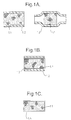
- salts of pre-selected reagents are formed into pellets which may be cylindrical or almond shaped. These pellets are then positioned within a sample stream and subject to dissolution over a period of time.
- the invention therefore solves the problem concerning prolonged dissolution by providing a simple housing for accommodating a number of reagent containers.
- the invention is particularly suitable for use with a flow through Anodic Stripping Voltammetry type system.
- a surprising advantage to be gained from the invention lies in the fact that reagents do not need to be pelletized prior to being placed in the containers. Rather, the reagents can be used in powdered form and may, preferably, be compacted into the containers.
- a suitable shape for the hollow compartment is that of a tube with the inlet and outlet ports being located at either end.
- the cross section of the tube can be circular.
- the reagent containers could also have the same shape as that of the cross section.
- a sintered disk can be provided behind the aperture means so as to prevent the ingress and egress of material.
- pelletization technology recognised only two shapes of pellets, the almond shape, so-called because of its similarity to the almond, and the cylindrical or rod shape.
- the almond shaped pellets exhibit more turbulent flow regimes around their surface than the cylinder or rod shaped pellets.
- the creation of turbulence is not desirable because it increases the rate at which the pellet is eroded. Therefore, cylindrical pellets are produced in preference to the almond shaped pellets.
- the process of manufacturing the pelletized reagent materials is carried out in a pellet dye and former. Manufacture of the reagent or ligand pellet is carried out by hand. The former is filled with the reagent to the required level. The dye is then lowered into the former by hydraulic action. A final forming pressure is applied before the dye is retracted and the pellet is removed from the former. The dimensions of a single pellet are variable according to requirements.
- the inventor has therefore developed a means for accommodating a reagent which overcomes the need for this preparatory treatment and which has a desirable dissolution rate.
- the present invention is illustrated in Figure 2.
- the reagent material is not pelletized but is compacted into small cylindrical housings 2.1 which are located in spaced and aligned relationship within a hollow compartment, 2.2.
- the hollow compartment, 2.2 comprises an outer tubular housing.
- Reagent housings 2.1 comprise cylindrical pots having friction fit fitted lids 2.7 with central apertures 2.8 therethrough.
- the housings 2.1 can have a sintered disk located behind the apertures, 2.8, in order to prevent the ingress of any other material or the egress of any material within it.
- a plurality of reagent housings 2.1 are filled with pre-selected reagents and then positioned within the hollow compartment 2.2 in an upright orientation so that one pot sits on the lid of another pot. Fluid entering the hollow compartment 2.2 flows through inlet chamber 2.5 in and around the reagent housings 2.1. This causes the reagents to be added to the fluid. The fluid leaves the hollow compartment 2.2 via outlet chamber 2.6 in the end 2.4, the fluid having been fortified with reagent.
- Figure 3 shows rate of dissolution of a pH reagent when housed in the apparatus of the invention. It can be seen that the dissolution curve is substantially flat thus indicating that, contrary to expectations, a non-pelletized reagent can be successfully housed in the apparatus in order to be dissolved at a constant rate.
- the invention therefore provides for a means of housing a plurality of unprepared reagents so that the dissolution rate of same can be optimally controlled.
Landscapes
- Chemical & Material Sciences (AREA)
- Chemical Kinetics & Catalysis (AREA)
- General Health & Medical Sciences (AREA)
- Life Sciences & Earth Sciences (AREA)
- Analytical Chemistry (AREA)
- Biochemistry (AREA)
- Physics & Mathematics (AREA)
- General Physics & Mathematics (AREA)
- Immunology (AREA)
- Pathology (AREA)
- Health & Medical Sciences (AREA)
- Organic Chemistry (AREA)
- Automatic Analysis And Handling Materials Therefor (AREA)
- Investigating Or Analyzing Non-Biological Materials By The Use Of Chemical Means (AREA)
Claims (10)
- Boítier de réactif destiné à être utilisé avec des systèmes d'échantillonnage à circulation, comprenant :
un compartiment (2.2) ayant un canal d'entrée (2.3) et un canal de sortie (2.4), plusieurs récipients (2.1) de réactif dont la dimension et la configuration sont telles qu'ils se logent dans le compartiment, les récipients comprenant un dispositif réceptacle ayant un couvercle amovible (2.7), les récipients pouvant être ouverts afin que les réactifs puissent être placés à l'intérieur, et chaque récipient comprenant un orifice (2.8) tel que le fluide qui s'écoule dans le compartiment peut dissoudre les réactifs contenus dans les récipients avec une vitesse pratiquement constante. - Boítier de réactif selon la revendication 1, dans lequel les récipients de réactif sont destinés à contenir les réactifs sous forme de pastilles.
- Boítier de réactif selon la revendication 1, dans lequel les récipients de réactif sont destinés à contenir le réactif sous forme de poudre.
- Boítier de réactif selon la revendication 3, dans lequel les récipients de réactif sont réalisés afin que le réactif puisse être comprimé dans les récipients.
- Boítier de réactif selon l'une quelconque des revendications précédentes, dans lequel le compartiment a une forme tubulaire, le canal d'entrée et le canal de sortie étant placés aux extrémités du tube.
- Boítier de réactif selon la revendication 5, dans lequel la forme de la section du compartiment est circulaire.
- Boítier de réactif selon la revendication 5 ou 6, dans lequel la forme de la section des récipients de réactif est à peu près la même que celle de la section du compartiment.
- Boítier de réactif selon l'une quelconque des revendications précédentes, dans lequel les récipients de réactif sont placés sous forme alignée à l'intérieur du compartiment.
- Boítier de réactif selon l'une quelconque des revendications précédentes, dans lequel chacun des récipients de réactif est destiné à contenir un réactif prédéterminé différent.
- Boítier de réactif selon l'une quelconque des revendications précédentes, dans lequel les récipients de réactif comportent en outre un disque fritté placé derrière l'orifice.
Applications Claiming Priority (2)
| Application Number | Priority Date | Filing Date | Title |
|---|---|---|---|
| GB939318959A GB9318959D0 (en) | 1993-09-14 | 1993-09-14 | Reagent dissolution in sensor systems |
| GB9318959 | 1993-09-14 |
Publications (3)
| Publication Number | Publication Date |
|---|---|
| EP0643298A2 EP0643298A2 (fr) | 1995-03-15 |
| EP0643298A3 EP0643298A3 (fr) | 1996-03-27 |
| EP0643298B1 true EP0643298B1 (fr) | 1998-11-18 |
Family
ID=10741937
Family Applications (1)
| Application Number | Title | Priority Date | Filing Date |
|---|---|---|---|
| EP94202639A Expired - Lifetime EP0643298B1 (fr) | 1993-09-14 | 1994-09-13 | Dispositif pour la dissolution des réactifs dans un système de capteurs |
Country Status (4)
| Country | Link |
|---|---|
| EP (1) | EP0643298B1 (fr) |
| DE (1) | DE69414668T2 (fr) |
| ES (1) | ES2126054T3 (fr) |
| GB (1) | GB9318959D0 (fr) |
Cited By (1)
| Publication number | Priority date | Publication date | Assignee | Title |
|---|---|---|---|---|
| CN101109741B (zh) * | 2007-08-24 | 2011-01-05 | 中电投远达环保工程有限公司 | 分仓式脱硝催化剂测试分析装置 |
Family Cites Families (4)
| Publication number | Priority date | Publication date | Assignee | Title |
|---|---|---|---|---|
| US3504376A (en) * | 1966-12-15 | 1970-03-31 | Xerox Corp | Automated chemical analyzer |
| US4522923A (en) * | 1983-10-03 | 1985-06-11 | Genetic Diagnostics Corporation | Self-contained assay method and kit |
| US4740475A (en) * | 1986-03-28 | 1988-04-26 | Medi-Scan, Inc. | Integral substance detection device and method |
| DE69122383T2 (de) * | 1991-08-22 | 1997-02-27 | Secr Defence Brit | Anodische Strip-Voltamperemetrie |
-
1993
- 1993-09-14 GB GB939318959A patent/GB9318959D0/en active Pending
-
1994
- 1994-09-13 DE DE69414668T patent/DE69414668T2/de not_active Expired - Lifetime
- 1994-09-13 ES ES94202639T patent/ES2126054T3/es not_active Expired - Lifetime
- 1994-09-13 EP EP94202639A patent/EP0643298B1/fr not_active Expired - Lifetime
Cited By (1)
| Publication number | Priority date | Publication date | Assignee | Title |
|---|---|---|---|---|
| CN101109741B (zh) * | 2007-08-24 | 2011-01-05 | 中电投远达环保工程有限公司 | 分仓式脱硝催化剂测试分析装置 |
Also Published As
| Publication number | Publication date |
|---|---|
| DE69414668D1 (de) | 1998-12-24 |
| EP0643298A3 (fr) | 1996-03-27 |
| EP0643298A2 (fr) | 1995-03-15 |
| DE69414668T2 (de) | 1999-04-15 |
| GB9318959D0 (en) | 1993-10-27 |
| ES2126054T3 (es) | 1999-03-16 |
Similar Documents
| Publication | Publication Date | Title |
|---|---|---|
| US3897213A (en) | Automated quantitative analysis of ionic species | |
| US7897032B2 (en) | Method and apparatus for stripping voltammetric and potentiometric detection and measurement of contamination in liquids | |
| DE2117098B2 (de) | Heizvorrichtung fur eine Ein richtung zur Analyse eines fließ fähigen Mediums, insbesondere von Blut | |
| US6438501B1 (en) | Flow through electrode with automated calibration | |
| US3839162A (en) | Method and apparatus for the determination of the concentration of relevant ions in aqueous solutions | |
| JP2004003937A (ja) | 活性物質の口腔溶解 | |
| US4058446A (en) | Anodic stripping voltammetry system and combination electrode assembly therefore | |
| JPH08505477A (ja) | 流体媒体分析装置 | |
| US3898042A (en) | Method and apparatus for continuously determining total copper in an aqueous stream | |
| US3498888A (en) | Method of performing coulometric analyses and an apparatus therefor | |
| EP0643298A2 (fr) | Dispositif pour la dissolution des réactifs dans un système de capteurs | |
| EP0214846A2 (fr) | Instrument de contrôle d'échantillon pour l'application on-line | |
| WO2002075254A2 (fr) | Titrage en flux continu | |
| RU94015270A (ru) | Анализатор жидких проб | |
| DE102013214384A1 (de) | Flüssigkeitsanalysator | |
| O’Brien et al. | Method for the in situ calibration of a passive phosphate sampler in estuarine and marine waters | |
| US5485099A (en) | Sensing method and device | |
| Gumbi et al. | Direct spectrophotometric detection of the endpoint in metachromatic titration of polydiallyldimethylammonium chloride in water | |
| Wang et al. | Electrochemical flow sensor for in-situ monitoring of total metal concentrations | |
| US7157059B1 (en) | Reduction device for nitrate determination | |
| Amato et al. | Characterization of the accumulation of metals and organic contaminants on a novel active-passive sampling device under controlled water flow conditions | |
| EP3877761B1 (fr) | Digestion du plomb (0) et détection colorimétrique ultérieure du plomb (ii) | |
| US4270922A (en) | Integrating corrosion monitor | |
| JPS58169058A (ja) | 陰イオンの分析方法およびその装置 | |
| DE20306104U1 (de) | Durchflussmesszelle für chemische und physikalische Sensoren |
Legal Events
| Date | Code | Title | Description |
|---|---|---|---|
| PUAI | Public reference made under article 153(3) epc to a published international application that has entered the european phase |
Free format text: ORIGINAL CODE: 0009012 |
|
| 17P | Request for examination filed |
Effective date: 19940914 |
|
| AK | Designated contracting states |
Kind code of ref document: A2 Designated state(s): DE ES FR GB GR IT NL |
|
| PUAL | Search report despatched |
Free format text: ORIGINAL CODE: 0009013 |
|
| AK | Designated contracting states |
Kind code of ref document: A3 Designated state(s): DE ES FR GB GR IT NL |
|
| 17Q | First examination report despatched |
Effective date: 19970124 |
|
| GRAG | Despatch of communication of intention to grant |
Free format text: ORIGINAL CODE: EPIDOS AGRA |
|
| GRAG | Despatch of communication of intention to grant |
Free format text: ORIGINAL CODE: EPIDOS AGRA |
|
| GRAH | Despatch of communication of intention to grant a patent |
Free format text: ORIGINAL CODE: EPIDOS IGRA |
|
| GRAH | Despatch of communication of intention to grant a patent |
Free format text: ORIGINAL CODE: EPIDOS IGRA |
|
| GRAA | (expected) grant |
Free format text: ORIGINAL CODE: 0009210 |
|
| AK | Designated contracting states |
Kind code of ref document: B1 Designated state(s): DE ES FR GB GR IT NL |
|
| ET | Fr: translation filed | ||
| REF | Corresponds to: |
Ref document number: 69414668 Country of ref document: DE Date of ref document: 19981224 |
|
| REG | Reference to a national code |
Ref country code: ES Ref legal event code: FG2A Ref document number: 2126054 Country of ref document: ES Kind code of ref document: T3 |
|
| PLBE | No opposition filed within time limit |
Free format text: ORIGINAL CODE: 0009261 |
|
| STAA | Information on the status of an ep patent application or granted ep patent |
Free format text: STATUS: NO OPPOSITION FILED WITHIN TIME LIMIT |
|
| 26N | No opposition filed | ||
| REG | Reference to a national code |
Ref country code: GB Ref legal event code: 732E |
|
| REG | Reference to a national code |
Ref country code: GB Ref legal event code: IF02 |
|
| REG | Reference to a national code |
Ref country code: FR Ref legal event code: TP |
|
| NLS | Nl: assignments of ep-patents |
Owner name: QINETIQ LIMITED |
|
| PGFP | Annual fee paid to national office [announced via postgrant information from national office to epo] |
Ref country code: ES Payment date: 20070911 Year of fee payment: 14 |
|
| PGFP | Annual fee paid to national office [announced via postgrant information from national office to epo] |
Ref country code: IT Payment date: 20070820 Year of fee payment: 14 |
|
| PGFP | Annual fee paid to national office [announced via postgrant information from national office to epo] |
Ref country code: GR Payment date: 20070830 Year of fee payment: 14 |
|
| PGFP | Annual fee paid to national office [announced via postgrant information from national office to epo] |
Ref country code: NL Payment date: 20080821 Year of fee payment: 15 |
|
| PG25 | Lapsed in a contracting state [announced via postgrant information from national office to epo] |
Ref country code: IT Free format text: LAPSE BECAUSE OF NON-PAYMENT OF DUE FEES Effective date: 20080913 |
|
| REG | Reference to a national code |
Ref country code: ES Ref legal event code: FD2A Effective date: 20080915 |
|
| PG25 | Lapsed in a contracting state [announced via postgrant information from national office to epo] |
Ref country code: GR Free format text: LAPSE BECAUSE OF NON-PAYMENT OF DUE FEES Effective date: 20090402 |
|
| PGFP | Annual fee paid to national office [announced via postgrant information from national office to epo] |
Ref country code: GB Payment date: 20090922 Year of fee payment: 16 |
|
| PG25 | Lapsed in a contracting state [announced via postgrant information from national office to epo] |
Ref country code: ES Free format text: LAPSE BECAUSE OF NON-PAYMENT OF DUE FEES Effective date: 20080915 |
|
| PGFP | Annual fee paid to national office [announced via postgrant information from national office to epo] |
Ref country code: DE Payment date: 20090922 Year of fee payment: 16 |
|
| REG | Reference to a national code |
Ref country code: NL Ref legal event code: V1 Effective date: 20100401 |
|
| PG25 | Lapsed in a contracting state [announced via postgrant information from national office to epo] |
Ref country code: NL Free format text: LAPSE BECAUSE OF NON-PAYMENT OF DUE FEES Effective date: 20100401 |
|
| GBPC | Gb: european patent ceased through non-payment of renewal fee |
Effective date: 20100913 |
|
| REG | Reference to a national code |
Ref country code: FR Ref legal event code: ST Effective date: 20110531 |
|
| REG | Reference to a national code |
Ref country code: DE Ref legal event code: R119 Ref document number: 69414668 Country of ref document: DE Effective date: 20110401 |
|
| PG25 | Lapsed in a contracting state [announced via postgrant information from national office to epo] |
Ref country code: DE Free format text: LAPSE BECAUSE OF NON-PAYMENT OF DUE FEES Effective date: 20110401 Ref country code: FR Free format text: LAPSE BECAUSE OF NON-PAYMENT OF DUE FEES Effective date: 20100930 |
|
| PG25 | Lapsed in a contracting state [announced via postgrant information from national office to epo] |
Ref country code: GB Free format text: LAPSE BECAUSE OF NON-PAYMENT OF DUE FEES Effective date: 20100913 |
|
| PGFP | Annual fee paid to national office [announced via postgrant information from national office to epo] |
Ref country code: FR Payment date: 20091001 Year of fee payment: 16 |