EP0643345A1 - Procédé et dispositif de traitement de données pour la surveillance des conditions de fonctionnement d'une installation technique - Google Patents
Procédé et dispositif de traitement de données pour la surveillance des conditions de fonctionnement d'une installation technique Download PDFInfo
- Publication number
- EP0643345A1 EP0643345A1 EP94113223A EP94113223A EP0643345A1 EP 0643345 A1 EP0643345 A1 EP 0643345A1 EP 94113223 A EP94113223 A EP 94113223A EP 94113223 A EP94113223 A EP 94113223A EP 0643345 A1 EP0643345 A1 EP 0643345A1
- Authority
- EP
- European Patent Office
- Prior art keywords
- diagnosis
- symptoms
- measured values
- symptom
- plant
- Prior art date
- Legal status (The legal status is an assumption and is not a legal conclusion. Google has not performed a legal analysis and makes no representation as to the accuracy of the status listed.)
- Granted
Links
- 238000012544 monitoring process Methods 0.000 title claims abstract description 16
- 238000003672 processing method Methods 0.000 title 1
- 208000024891 symptom Diseases 0.000 claims abstract description 147
- 238000003745 diagnosis Methods 0.000 claims abstract description 76
- 238000000034 method Methods 0.000 claims abstract description 25
- 238000012545 processing Methods 0.000 claims abstract description 20
- 230000015654 memory Effects 0.000 claims description 40
- 230000009471 action Effects 0.000 claims description 30
- 238000005259 measurement Methods 0.000 claims description 14
- 230000008878 coupling Effects 0.000 claims description 11
- 238000010168 coupling process Methods 0.000 claims description 11
- 238000005859 coupling reaction Methods 0.000 claims description 11
- 230000006870 function Effects 0.000 claims description 9
- 238000004088 simulation Methods 0.000 claims description 6
- 238000002560 therapeutic procedure Methods 0.000 claims description 5
- 238000009434 installation Methods 0.000 claims description 3
- 238000006243 chemical reaction Methods 0.000 claims description 2
- 238000012806 monitoring device Methods 0.000 abstract description 5
- 230000008569 process Effects 0.000 abstract description 3
- 238000007726 management method Methods 0.000 abstract description 2
- 238000013144 data compression Methods 0.000 abstract 1
- 230000001419 dependent effect Effects 0.000 abstract 1
- UFHFLCQGNIYNRP-UHFFFAOYSA-N Hydrogen Chemical compound [H][H] UFHFLCQGNIYNRP-UHFFFAOYSA-N 0.000 description 23
- 239000001257 hydrogen Substances 0.000 description 23
- 229910052739 hydrogen Inorganic materials 0.000 description 23
- 238000010586 diagram Methods 0.000 description 14
- 238000001816 cooling Methods 0.000 description 9
- 230000006835 compression Effects 0.000 description 8
- 238000007906 compression Methods 0.000 description 8
- 239000007789 gas Substances 0.000 description 7
- 230000004913 activation Effects 0.000 description 5
- 230000000630 rising effect Effects 0.000 description 4
- 230000006403 short-term memory Effects 0.000 description 4
- 239000012080 ambient air Substances 0.000 description 3
- 238000012360 testing method Methods 0.000 description 3
- 230000007547 defect Effects 0.000 description 2
- 238000001514 detection method Methods 0.000 description 2
- 230000010354 integration Effects 0.000 description 2
- 238000012417 linear regression Methods 0.000 description 2
- 238000004519 manufacturing process Methods 0.000 description 2
- 230000026676 system process Effects 0.000 description 2
- 230000000007 visual effect Effects 0.000 description 2
- 238000012935 Averaging Methods 0.000 description 1
- 239000003570 air Substances 0.000 description 1
- 238000004364 calculation method Methods 0.000 description 1
- 230000008859 change Effects 0.000 description 1
- 239000002826 coolant Substances 0.000 description 1
- 230000003247 decreasing effect Effects 0.000 description 1
- 230000002950 deficient Effects 0.000 description 1
- 230000004069 differentiation Effects 0.000 description 1
- 238000011156 evaluation Methods 0.000 description 1
- 239000000446 fuel Substances 0.000 description 1
- 125000000524 functional group Chemical group 0.000 description 1
- 230000006872 improvement Effects 0.000 description 1
- 238000012423 maintenance Methods 0.000 description 1
- 230000007257 malfunction Effects 0.000 description 1
- 238000012986 modification Methods 0.000 description 1
- 230000004048 modification Effects 0.000 description 1
- 238000002360 preparation method Methods 0.000 description 1
- 230000008439 repair process Effects 0.000 description 1
- 230000001960 triggered effect Effects 0.000 description 1
Images
Classifications
-
- G—PHYSICS
- G05—CONTROLLING; REGULATING
- G05B—CONTROL OR REGULATING SYSTEMS IN GENERAL; FUNCTIONAL ELEMENTS OF SUCH SYSTEMS; MONITORING OR TESTING ARRANGEMENTS FOR SUCH SYSTEMS OR ELEMENTS
- G05B23/00—Testing or monitoring of control systems or parts thereof
- G05B23/02—Electric testing or monitoring
- G05B23/0205—Electric testing or monitoring by means of a monitoring system capable of detecting and responding to faults
- G05B23/0218—Electric testing or monitoring by means of a monitoring system capable of detecting and responding to faults characterised by the fault detection method dealing with either existing or incipient faults
- G05B23/0224—Process history based detection method, e.g. whereby history implies the availability of large amounts of data
- G05B23/0227—Qualitative history assessment, whereby the type of data acted upon, e.g. waveforms, images or patterns, is not relevant, e.g. rule based assessment; if-then decisions
- G05B23/0229—Qualitative history assessment, whereby the type of data acted upon, e.g. waveforms, images or patterns, is not relevant, e.g. rule based assessment; if-then decisions knowledge based, e.g. expert systems; genetic algorithms
-
- G—PHYSICS
- G05—CONTROLLING; REGULATING
- G05B—CONTROL OR REGULATING SYSTEMS IN GENERAL; FUNCTIONAL ELEMENTS OF SUCH SYSTEMS; MONITORING OR TESTING ARRANGEMENTS FOR SUCH SYSTEMS OR ELEMENTS
- G05B23/00—Testing or monitoring of control systems or parts thereof
- G05B23/02—Electric testing or monitoring
- G05B23/0205—Electric testing or monitoring by means of a monitoring system capable of detecting and responding to faults
- G05B23/0259—Electric testing or monitoring by means of a monitoring system capable of detecting and responding to faults characterized by the response to fault detection
- G05B23/0275—Fault isolation and identification, e.g. classify fault; estimate cause or root of failure
- G05B23/0278—Qualitative, e.g. if-then rules; Fuzzy logic; Lookup tables; Symptomatic search; FMEA
Definitions
- the invention relates to a method and a data processing system for monitoring operating states of a technical system.
- technical systems are also understood to mean, for example, fossil-fueled or nuclear power plants as well as manufacturing and production facilities.
- monitoring devices should make the current operating states of the plant recognizable and report deviations from a target state.
- a generally usable monitoring device is known for example from DE-OS 38 12 618.
- a special fault tracking device, which can be part of a monitoring device, is known from DE-OS 38 32 789.
- turbo sets comprise, as functional groups, the gas or steam turbine as well as generators coupled to them via different shafts and a steam generator or a condenser.
- these can also be, for example, the components and auxiliary systems of the fuel / air supply and the burner control and the cooling of the generators.
- Important components and auxiliary systems are also the components and auxiliary systems of the gas or steam turbine.
- a signal or data exchange is usually carried out via a bus system within a control system common to the system parts, with which the operating states of the system are controlled and monitored partially or fully automatically.
- the invention is therefore based on the object of specifying a method and a data processing system for monitoring the operating states of a technical system, in particular a gas and / or steam turbine system, with which, based on extensive measurement value acquisition, high operational reliability and high system availability with a particularly high information compression at the same time can be achieved.
- the importance value then assigned to the system symptom is therefore a measure of how much the operating state corresponding to the system symptom deviates from a preferred operating state and is therefore a measure of the malfunction of the operation. Because of one or more system symptoms depending on the associated one Importance value, a diagnosis of the operating state of the system is created, there is a particularly high information compression, because based on the importance values an advantageous selection for the operation of the system of the pending system symptoms can be carried out.
- a diagnosis is first derived from one or more system symptoms, which is then checked for its relevance with regard to trouble-free operation of the system using further rules derived from technological knowledge.
- the importance value then assigned to the diagnosis is also a measure of how much the operating state corresponding to the diagnosis deviates from a preferred operating state. It is therefore a measure of the disruption to the operation of the system.
- the importance value assigned according to this diagnosis allows a particularly high information compression, since the importance values are used to decide when a diagnosis is output to the user interface and when not.
- the measured values are provided with a measuring point-specific identifier and status information and are addressed by means of the identifier.
- a so-called data telegram is generated which can be addressed safely and which can be found without error in a memory of the data processing system.
- Based on the status information such. B. 0, NOT READY, NOT FOUND, BAD VALUE, an assessment of the confidence level of the measured value can be carried out.
- the identifiers and status information of the measured values originally causing the system symptoms being adopted for the system symptoms.
- the individual measurement-specific rules of technological knowledge can, for example, target-actual value comparisons, limit value checks and the use of functions such as. B. polynomials on the measured values. For example, for leakage monitoring of the hydrogen cooling of the generators, symptoms are derived which have statements, such as. B.
- system symptoms can also be processed, which have been derived from, for example, non-plausible measured values.
- the transferred status information e.g. B. "BAD VALUE” ensures the identification of such "faulty" system symptoms.
- a diagnosis of the operating state is made from the system symptoms if the importance value associated with the system symptom exceeds the confidence threshold associated with the system symptom.
- a diagnosis can first be made from the system symptoms, which is only passed on to the user interface if the importance value assigned to the diagnosis exceeds the associated confidence threshold.
- a particularly weighted selection condition is made on the basis of the operating experience on which the technological knowledge is based, so that, for example, the operating personnel in the control room only has to deal with a diagnosis in situations which are particularly critical for the trouble-free operation of the system.
- the requirements placed on the operating personnel are limited to those cases in which further monitoring of the measured values and fully automatic adjustment of actuators in the system which have changed in the operating state cannot necessarily lead to success.
- the operating personnel receive a quick overview of the current operating status of the system if, based on the diagnosis, the system symptom, its associated symptom description, ie causes and consequences, and a therapy proposal based on the technological knowledge regarding this system symptom or diagnosis are sent to the user interface an electronic data processing system is issued.
- This enables early detection of impending defects and an immediate reaction to the current system status. This can go so far that if a diagnosis is available depending on the operating personnel or independent of operating personnel, the necessary measures for trouble-free continued operation are initiated or the system or system parts are switched off.
- the operational safety and availability of the system can be further increased by modifying the measurement-specific rules and the confidence rules as well as the confidence thresholds as required via the user interface.
- the associated importance value of the system symptom must then be higher in accordance with the raised confidence threshold so that a diagnosis can be made from the system symptom.
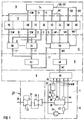
- the functional diagram shown in FIG. 1 of a device for monitoring the operating states of a technical system comprises building blocks and components which are arranged in six successive levels 4 to 14 and are named below with the description of the functional diagram.
- the technical system to be monitored in the exemplary embodiment is a gas and steam turbine power plant system which is only indicated here.
- the system process 16 to be monitored with the diagnostic system 2 is, in the exemplary embodiment, the hydrogen cooling circuit of a generator 18.
- the generator 18 is arranged on a common shaft 28 with a steam turbine 20, which comprises a high pressure part 22, a medium pressure part 24 and a low pressure part 26, the Generator 18 is driven by the steam turbine 20.
- a gas compressor 34, a hydrogen reservoir 32 with an integrated cooling stage, a hydrogen flow, temperature and pressure meter 38, the heat exchanger channels of the generator 18 and a further hydrogen flow, temperature and pressure meter 42 are installed in sequence in the closed hydrogen cooling circuit on a hydrogen line 30 .
- a level meter 36, a generator temperature meter 40 and a hydrogen detector 44 arranged in the immediate vicinity of the generator 18 are provided for monitoring the hydrogen cooling circuit.
- These means 36 to 44 for measured value acquisition send their measured values MW from the first level, hereinafter referred to as measuring level 4, via separate data lines to a second level, hereinafter referred to as coupling level 6, to a coupling module 46.
- This coupling module 46 prepares the measured values MW for their further processing on what means in detail that the measured values MW digitized, syntactically processed, provided with a measuring point-specific identifier and status information.
- a syntactical processing is understood, for example, to mean that the measured values MW are converted into integer values and are provided with control characters such that this integer value (integer value) consisting of three bytes, for example in the order of very significant byte (most significant byte ), moderately significant byte (medium significant byte) and low significant byte (low significant byte).
- the measured values MW can, however, just as well be transmitted, for example, as eight byte real numbers.
- the measured values MW that have now been processed are transmitted as a measured value telegram MT to a coupling-addressing module 48 in a third level, hereinafter referred to as management level 8.
- the coupling-addressing module 48 addresses the measured value telegram MT to the subsequent components and here transmits the addressed measured value telegram MT to a first action module 50 in a fourth level, hereinafter referred to as action level 10.
- action level 10 The function of the action module 50 is explained in more detail below in relation to FIG. 2. At this point it should first be said that the measured value telegram MT is transmitted directly to a short-term memory 52 and a database 54 by means of the action module 50.
- the short-term memory 52 and the database 54 are arranged in a fifth level, hereinafter referred to as data level 12.
- data level 12 there are also a symptom memory 56, a memory 58 for measured value-specific rules SR, which are specific for the measured value telegram MT, and a memory 60 for confidence rules KR, ie also qualification-determining membership functions.
- SR measured value-specific rules
- KR confidence rules
- a measured value telegram MT arrives at the action module 50, data are retrieved from the memories 58, 60.
- the measured value telegram MT is qualified for system symptoms S, which are output to the symptom memory 56.
- the system symptoms S are important values assigned, which are output as a trigger telegram TT to a further coupling addressing module 62.
- the trigger telegram TT goes hierarchically back into the data level 6 and is addressed in the coupling level 8 on the basis of the associated identifier by means of the coupling addressing component 62 to one of the further action components 64, 66.
- These further action modules 64, 66 are designed as inference servers, which are addressed in accordance with their address with a trigger telegram TT specific for this address and then identify the system symptom S or a number of system symptoms which can be identified in accordance with the identifier transmitted with the trigger telegram TT. retrieve symptoms S from symptom memory 56.
- An action module for example the action module 64, which loads a system symptom S from the symptom memory 56 after a trigger telegram TT arrives, calls from a memory 68 for symptom-specific knowledge SW symptom-specific knowledge SW, i. H. the associated symptom description SB, the associated diagnosis texts DT, linking rules VR and at least one therapy suggestion TV derived from the system symptom S.
- a memory 70 for symptom-specific knowledge SW is networked in the exemplary embodiment in such a way that data can be exchanged with one another in any direction.
- the diagnosis D generated by the action module 64 or the action module 66 is stored in a result memory 72 located in the data level 12.
- the diagnosis D once generated, is transmitted directly from the result memory 72 to a user interface 74, which is arranged in a sixth level, hereinafter referred to as the display level 14.
- This user interface 74 comprises one or more terminals in which the diagnosis D is displayed optically for the operating personnel of the power plant. If necessary, in addition to the displayed diagnosis D, the operating personnel can now call up further symptom-specific knowledge SW, the system symptom (s) S and the measured value telegram MT in the user interface 74 in order to be able to carry out a comprehensive assessment of the displayed diagnosis D.
- the diagnosis result can be understood and the knowledge learned in this way can also be stored from the user interface 74 as a new measurement-specific rule SR and confidence rule KR in the associated memories 58 and 60 of the data level 12.
- the diagnostic system 2 shown in FIG. 1 particularly fulfills the requirement for the highest possible information compression in order to provide the operating personnel with the operating state of the power plant in a particularly user-friendly manner only in particularly important cases.
- This requirement is essentially implemented by the creation of the trigger telegrams TT, which only permit the creation of the diagnosis D from a system symptom S if a trigger telegram TT is actually sent out by the first action module 50.
- each system symptom S is initially accompanied by a trigger telegram TT, which is used to create the diagnosis associated with the system symptom S. D allowed. Only then is this diagnosis D checked by means of a comparison with the confidence threshold KS 'belonging to the diagnosis D (see FIG. 6) for its relevance for trouble-free operation of the power plant.
- the diagnoses D which then exceed the associated confidence thresholds KS ', can, for example, cause an alarm signal in the user interface 74 or can be output as a "high-light message" to a data display device in the user interface 74, the "high-light Message "only goes out and” rolls "out of the data display device when the operating state triggering diagnosis D has been remedied.
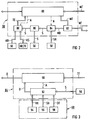
- the functional diagram of the first action module 50 is shown in detail in FIG.
- the measured value telegram MT, d. H. the syntactically processed measured values MW, which are provided with an identifier and status information, first pass from the coupling-addressing module 48 to a so-called trigger server 80.
- the trigger server 80 pushes the measured value telegram MT to an interface 82.
- This interface 82 stores the measured value telegram MT between and on the one hand sends the measured value telegram MT directly to the short-term memory 52 and the database 54.
- the interface 82 now passes the measured value telegram MT block by block as a measured value block MB to a measured value evaluator 84.
- Activation A of the measured value evaluator 84 is triggered by the arrival of a measured value telegram MT in Trigger server 80 causes.
- the individual measured value blocks MB contain the syntactically processed measured value MW, its associated identifier, its associated status information and control characters for identifying the start and end of the measured value block MB and for separating the measured value, identifier and status information.
- the measured value evaluator 84 firstly prepares the measured value, for example, in accordance with the identifier of the measured value block. B. linear regression, integration, etc., by. In addition, the measured value evaluator 84 loads on the basis of the identifier that can be identified and only the rules SR specific for this measured value. ie also the membership functions required for fuzzification from the associated memory 58. Exactly these rules SR are identified on the basis of the identifier which is transmitted in the measured value block MB. These measured value-specific rules SR can be, for example, target / actual value comparisons, limit value checks or also mathematical calculations.
- the originally existing measured value MW is converted into a system symptom S.
- the statement “throughput rising slightly” is then derived as system symptom S, for example.
- Other statements can be, for example, "pressure falling slightly”, “temperature almost constant” or "hydrogen concentration in ambient air rising very slightly”.
- Another interface 86 sends the system symptom S formed directly to the symptom memory 56 and to a symptom evaluator 88.
- This symptom evaluator 88 now has the task of referring to the system symptom S individually or in connection with other system symptoms S or to check their relevance with regard to trouble-free operation of the power plant. In the end, he decides whether a diagnosis D should be made from the system symptom S. For this purpose, the symptom evaluator 88 loads the confidence rules KR regarding this system symptom S (identified on the basis of the identifier) from the associated memory 60 and the symptom knowledge SW from the associated memory (s) 68, 70. The system symptom S is assigned an importance value based on the confidence rules KR.
- This importance value lies, for example, on a standardized scale between 0 and 1.
- the confidence threshold KS loaded with the symptom knowledge SW with respect to this system symptom S now allows a comparison of the importance value and the confidence threshold KS.
- the statement “Slightly increasing throughput” can, for example, be evaluated in such a way that it is assigned an importance value which is below the confidence threshold. Therefore, no diagnosis D is made from this system symptom S below.
- the statements "pressure falling slightly” and "temperature almost constant” with their associated importance values can be significantly below their associated confidence thresholds KS.
- the hydrogen cooling circuit of the generator 18 For the system process 16 to be monitored, here the hydrogen cooling circuit of the generator 18, the statement "hydrogen in ambient air increases very slightly" is significantly more relevant.
- the importance value of this system symptom S exceeds the associated confidence threshold KS, i. H. Due to the technological knowledge, this system symptom S can jeopardize the trouble-free operation of the power plant.
- the symptom evaluator 88 then sends a trigger event TE to the trigger server 80, which then immediately sends a trigger telegram TT.
- This trigger telegram TT also includes the identifier transmitted from the measured value telegram MT to the system symptom S, so that only the action module 64 or 66 assigned to this identifier can load the system symptom S from the symptom memory 56.
- FIG. 3 shows the functional diagram of the second action module 64.
- a trigger telegram TT sent by the trigger server 80 arrives in a diagnostic server 90 of the associated action module 64 after it has been addressed.
- the diagnosis server 90 initiates activation A of a diagnosis evaluator 92.
- the diagnosis interpreter 92 then calls the system symptom S which triggers the associated trigger telegram TT from the symptom memory 56. In the present case, this symptom is "hydrogen concentration in ambient air increases very slightly”.
- From the symptom-specific Memory 68 retrieves the symptom-specific knowledge SW, specifically the linking rules VR, the symptom description SB and the diagnostic text DT, which are stored in separate memories 94, 96 and 98, respectively.
- the diagnostic evaluator 92 initiates an evaluation of the system symptom S leading to the diagnosis D with other system symptoms S, for example from the symptom memory 56, the importance values of which have remained below the confidence thresholds KS.
- the diagnosis D created by the diagnosis evaluator 92 is forwarded directly to the diagnosis server 90, which loads the diagnosis D into the result memory 72 and outputs it directly to the user interface 74.
- the operating personnel can be shown, for example, as a result that the leakage occurs at the entrance to the hydrogen reservoir 32 and that there are probably Simmerrings in the screw connection of the hydrogen line 30 and the hydrogen reservoir 32 defective.
- the chain of logical and arithmetic operations that led to the diagnosis D on the basis of the measured value MW can be comprehensively understood by the operating personnel via the user interface 74.
- the confidence rules KR are derived too generously for certain system symptoms S, or that a confidence threshold KS has been set too high based on the technological knowledge TW.
- the operating personnel can load such experiences directly into the memories 58, 60, 68, 70 affected by the modifications via the user interface 74.
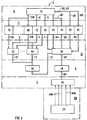
- FIG. 4 shows the functional diagram of the same diagnostic system 2 from FIG. 1 again.
- the simulation level 100 essentially comprises a data memory 102 for measured values MW.
- These measured values MW can originate, for example, from an operating interval of the technical plant process 16, here the hydrogen cooling circuit of the generator 18.
- the measured values MW stored in the data memory 102 can be called up from the database 54.
- the operating personnel are given the opportunity to simulate the operation of the technical system and to artificially generate particularly critical system states by manipulating the stored measured values MW.
- These simulations of the operating states lead to an improvement in the understanding of the generally existing complexity of the technical system. This improved understanding in turn extends the technological knowledge TW and is reflected in modified, now even more finely coordinated rules SR, KR, confidence thresholds KS and correspondingly adapted symptom-specific knowledge SW.
- the technological knowledge TW is stored in the data level 12 and is divided into the symptom-specific knowledge SW stored in the memories 68, 70, the measurement-specific rules SR stored in the memory 58 and the confidence rules KR stored in the memory 60.
- the diagnostic system 2 explained in FIGS. 1 to 6 is suitable on the basis of the structure described for monitoring the operating states of various technical systems.
- the technological knowledge TW that is significant for the respective system is contained in the measurement-specific rules SR, in the confidence rules KR, and in the confidence thresholds KS, which are contained in the symptom-specific knowledge SW.
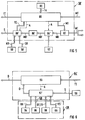
- the functional diagram shown in FIG. 5 of a first action module 50 ' which is slightly modified compared to FIG. 2 also differs only slightly in structure from the functional diagram in FIG. 2.
- a measured value telegram MT arriving at the trigger server 80 from the coupling / addressing module 48 is also applied to the interface 82 and forwarded to a measured value evaluator 84 'as well as to the short-term memory 52 and the database 54.
- An activation A of the measured value evaluator 84 ' is also caused by the arrival of the measured value telegram MT from the trigger server 80.
- the processing of the measured value block MB is first carried out in the measured value evaluator 84 '.
- This preparation includes statistical operations, such as. B. linear regression and arithmetic operations such. B. Differentiation, integration and averaging.
- the mathematical functional instructions and data required for this are loaded from a memory 57, identifiable on the basis of the identifier and the status information of the measured value block MB.
- the measured value block MB 'prepared in this way is loaded by the measured value evaluator 84' into a further interface 86 '. Simultaneously with the activation A of the measured value evaluator 84 ', a symptom evaluator 88' is also activated. As long as, for example, the measured value evaluator 84 'is still processing the measured value block MB, the symptom evaluator 88 loads' measured value blocks MB' which have the status NOT READY. This means that that is sent to trigger server 80 Trigger event TE does not trigger trigger telegram TT.
- the symptom evaluator 88' loads the measured value-specific rules SR, i. H. also the membership functions required for fuzzification, and the confidence rules KR. Using these rules, the modified measured value block MB 'is converted into a system symptom S, which is loaded into the symptom memory 56. This system symptom S is also given the identifier and the status information of the measured value block MB. At the same time, this system symptom S is given to the trigger server 80 as a qualified trigger event TE. Using a trigger event trigger telegram table 89, the trigger event TE is linked to trigger addresses TA loaded from table 89 to form the trigger telegram TT.
- a trigger telegram TT arriving at the diagnosis server 90 automatically activates a diagnosis evaluator 92 '. After its activation, this diagnostic evaluator 92 'loads the system symptom S which can be identified in accordance with its identifier or also a plurality of system symptoms S which can be identified on the basis of the identifier.
- a diagnosis D is derived from the symptom or the system symptoms S on the basis of the linking rules VR.
- Linking rules VR, symptom descriptions can also be used SB, diagnostic texts DT and confidence thresholds KS 'other memories, z. B. memory 70, for symptom-specific knowledge SW to help.
- diagnosis D is assigned an importance value on the basis of the symptom-specific knowledge SW, which is compared with the confidence thresholds KS 'loaded by the diagnosis evaluator 92'. For example, if the importance value of a diagnosis D exceeds its associated confidence threshold KS ', the status information of the diagnosis D can be set from 0 to 1, for example. Such a diagnosis is prepared with particular priority on the basis of the status information identifiable by "1" in the user interface 74. This can be done, for example, in that diagnoses D with the status information 0 are usually displayed in a data display device operated in roll mode, output on a printer and "rolled out" of the data display device after a certain time, depending on the number of subsequent diagnoses D.
- a diagnosis with status information 1 is output, for example, as a "high-light message” on the visual display device and is initially not “rolled out” of the visual display device. Only when the therapy on which this diagnosis D is based has led to success, which is equivalent to continued trouble-free operation of the technical system, does this "high-light message” go out and then, like the diagnoses D provided with status information 0, is then rolled out of the data display device and printed out for documentation purposes.
- the building blocks and components introduced in the functional diagrams can not only be present as physically existing building blocks and components in a data processing system, but they can also be generated virtually via corresponding software definitions. In this way it is possible to be able to use workstations and personal computers as the heart of this or similar diagnostic systems 2.
Landscapes
- Engineering & Computer Science (AREA)
- Physics & Mathematics (AREA)
- General Physics & Mathematics (AREA)
- Automation & Control Theory (AREA)
- Mathematical Physics (AREA)
- Quality & Reliability (AREA)
- Fuzzy Systems (AREA)
- Life Sciences & Earth Sciences (AREA)
- Bioinformatics & Cheminformatics (AREA)
- Bioinformatics & Computational Biology (AREA)
- Evolutionary Biology (AREA)
- Testing And Monitoring For Control Systems (AREA)
- Alarm Systems (AREA)
Applications Claiming Priority (2)
| Application Number | Priority Date | Filing Date | Title |
|---|---|---|---|
| DE4329714 | 1993-09-02 | ||
| DE4329714 | 1993-09-02 |
Publications (2)
| Publication Number | Publication Date |
|---|---|
| EP0643345A1 true EP0643345A1 (fr) | 1995-03-15 |
| EP0643345B1 EP0643345B1 (fr) | 1998-10-21 |
Family
ID=6496720
Family Applications (1)
| Application Number | Title | Priority Date | Filing Date |
|---|---|---|---|
| EP94113223A Expired - Lifetime EP0643345B1 (fr) | 1993-09-02 | 1994-08-24 | Dispositif de traitement de données pour la surveillance des conditions de fonctionnement d'une installation technique |
Country Status (4)
| Country | Link |
|---|---|
| US (1) | US5625574A (fr) |
| EP (1) | EP0643345B1 (fr) |
| DE (1) | DE59407119D1 (fr) |
| ES (1) | ES2123692T3 (fr) |
Cited By (9)
| Publication number | Priority date | Publication date | Assignee | Title |
|---|---|---|---|---|
| WO1997006475A1 (fr) * | 1995-08-09 | 1997-02-20 | Siemens Aktiengesellschaft | Systeme d'analyse pour installation industrielle, notamment pour centrale electrique |
| WO1997006474A1 (fr) * | 1995-08-09 | 1997-02-20 | Siemens Aktiengesellschaft | Procede pour l'analyse de signaux de processus dans une installation industrielle, notamment dans une centrale electrique |
| WO1998040800A1 (fr) * | 1997-03-13 | 1998-09-17 | Intelligent Applications Limited | Systeme de controle |
| WO1999027428A1 (fr) * | 1997-11-19 | 1999-06-03 | Siemens Aktiengesellschaft | Procede pour determiner la disponibilite d'une installation technique |
| WO2002082198A1 (fr) * | 2001-04-04 | 2002-10-17 | Siemens Aktiengesellschaft | Procede et systeme pour visualiser des informations relatives a un diagnostic |
| EP1071985B1 (fr) * | 1998-04-17 | 2003-06-25 | Siemens Aktiengesellschaft | Composante logicielle pour un systeme de diagnostic avec projection assistee |
| EP0751446B1 (fr) * | 1996-09-28 | 2003-12-10 | Maag Pump Systems Textron AG | Méthode et dispositif de surveillance d'unités d'un système |
| AT504447B1 (de) * | 2006-08-25 | 2008-11-15 | Omv Refining & Marketing Gmbh | Verfahren zur darstellung von betriebszuständen einer chemischen und/oder physikalischen anlage |
| DE102007029930A1 (de) * | 2007-06-28 | 2009-01-02 | Dürr Systems GmbH | Verfahren und Vorrichtung zur Überwachung einer technischen Anlage |
Families Citing this family (26)
| Publication number | Priority date | Publication date | Assignee | Title |
|---|---|---|---|---|
| DE4438859C2 (de) * | 1994-11-02 | 1996-12-12 | Siemens Ag | Verfahren zur Analyse von Prozeßdaten einer technischen Anlage |
| US6298454B1 (en) | 1999-02-22 | 2001-10-02 | Fisher-Rosemount Systems, Inc. | Diagnostics in a process control system |
| US8044793B2 (en) | 2001-03-01 | 2011-10-25 | Fisher-Rosemount Systems, Inc. | Integrated device alerts in a process control system |
| US6633782B1 (en) | 1999-02-22 | 2003-10-14 | Fisher-Rosemount Systems, Inc. | Diagnostic expert in a process control system |
| US7206646B2 (en) * | 1999-02-22 | 2007-04-17 | Fisher-Rosemount Systems, Inc. | Method and apparatus for performing a function in a plant using process performance monitoring with process equipment monitoring and control |
| US7562135B2 (en) * | 2000-05-23 | 2009-07-14 | Fisher-Rosemount Systems, Inc. | Enhanced fieldbus device alerts in a process control system |
| DE50001644D1 (de) * | 1999-07-28 | 2003-05-08 | Siemens Ag | Diagnoseverfahren und diagnosesystem für eine technische anlage |
| PT1261897E (pt) * | 2000-02-25 | 2005-02-28 | Siemens Ag | Processo para operar e dispositivo para monitorar uma instalacao tecnica |
| AU2000264369A1 (en) * | 2000-07-22 | 2002-02-05 | Abb Research Ltd | System and method for generating an xml-based error model |
| EP1217486A1 (fr) * | 2000-12-21 | 2002-06-26 | ABB Schweiz AG | Procédé pour la planification d'entretien des installations industrielles |
| US7720727B2 (en) | 2001-03-01 | 2010-05-18 | Fisher-Rosemount Systems, Inc. | Economic calculations in process control system |
| EP1364263B1 (fr) * | 2001-03-01 | 2005-10-26 | Fisher-Rosemount Systems, Inc. | Partage de donnees dans une installation de traitement |
| US8073967B2 (en) | 2002-04-15 | 2011-12-06 | Fisher-Rosemount Systems, Inc. | Web services-based communications for use with process control systems |
| US6813532B2 (en) * | 2001-03-01 | 2004-11-02 | Fisher-Rosemount Systems, Inc. | Creation and display of indices within a process plant |
| DE10343963A1 (de) * | 2003-09-19 | 2005-04-14 | Siemens Ag | Bereitstellung von Diagnoseinformationen |
| US9201420B2 (en) | 2005-04-08 | 2015-12-01 | Rosemount, Inc. | Method and apparatus for performing a function in a process plant using monitoring data with criticality evaluation data |
| US8005647B2 (en) | 2005-04-08 | 2011-08-23 | Rosemount, Inc. | Method and apparatus for monitoring and performing corrective measures in a process plant using monitoring data with corrective measures data |
| US7272531B2 (en) * | 2005-09-20 | 2007-09-18 | Fisher-Rosemount Systems, Inc. | Aggregation of asset use indices within a process plant |
| JP2007279955A (ja) * | 2006-04-05 | 2007-10-25 | Yokogawa Electric Corp | プラント設備管理装置 |
| US8301676B2 (en) | 2007-08-23 | 2012-10-30 | Fisher-Rosemount Systems, Inc. | Field device with capability of calculating digital filter coefficients |
| US7702401B2 (en) | 2007-09-05 | 2010-04-20 | Fisher-Rosemount Systems, Inc. | System for preserving and displaying process control data associated with an abnormal situation |
| US8055479B2 (en) | 2007-10-10 | 2011-11-08 | Fisher-Rosemount Systems, Inc. | Simplified algorithm for abnormal situation prevention in load following applications including plugged line diagnostics in a dynamic process |
| GB0911836D0 (en) * | 2009-07-08 | 2009-08-19 | Optimized Systems And Solution | Machine operation management |
| US9927788B2 (en) | 2011-05-19 | 2018-03-27 | Fisher-Rosemount Systems, Inc. | Software lockout coordination between a process control system and an asset management system |
| DE102013205356B4 (de) * | 2013-03-26 | 2016-07-07 | Siemens Aktiengesellschaft | Verfahren zur rechnergestützten Steuerung und/oder Regelung eines technischen Systems |
| DE102018123436A1 (de) * | 2018-09-24 | 2020-03-26 | Endress+Hauser Conducta Gmbh+Co. Kg | Verfahren zum Überwachen einer Anlage der Automatisierungstechnik |
Citations (4)
| Publication number | Priority date | Publication date | Assignee | Title |
|---|---|---|---|---|
| JPS61228501A (ja) * | 1985-04-01 | 1986-10-11 | Nippon Atom Ind Group Co Ltd | プラントの異常時処置決定方法 |
| JPH02224096A (ja) * | 1989-02-21 | 1990-09-06 | Toshiba Corp | プラントの異常時運転支援システム |
| US5132920A (en) * | 1988-02-16 | 1992-07-21 | Westinghouse Electric Corp. | Automated system to prioritize repair of plant equipment |
| WO1993005477A1 (fr) * | 1991-09-10 | 1993-03-18 | Zellweger Uster Ag | Systeme pour le diagnostic de derangements dans une machine de production et utilisation dudit systeme dans des machines textiles |
Family Cites Families (12)
| Publication number | Priority date | Publication date | Assignee | Title |
|---|---|---|---|---|
| US4649515A (en) * | 1984-04-30 | 1987-03-10 | Westinghouse Electric Corp. | Methods and apparatus for system fault diagnosis and control |
| US4642782A (en) * | 1984-07-31 | 1987-02-10 | Westinghouse Electric Corp. | Rule based diagnostic system with dynamic alteration capability |
| YU31287A (en) * | 1986-04-16 | 1989-04-30 | Siemens Ag | Mutual controlling system |
| JPH0832095B2 (ja) * | 1987-04-15 | 1996-03-27 | 中部電力株式会社 | プラント監視装置 |
| GB2211324B (en) * | 1987-10-16 | 1992-01-15 | Mitsubishi Electric Corp | Fuzzy inference apparatus |
| KR890007306A (ko) * | 1987-10-30 | 1989-06-19 | 제트.엘.더머 | 온라인 밸브 진단 감시 시스템 |
| US5081598A (en) * | 1989-02-21 | 1992-01-14 | Westinghouse Electric Corp. | Method for associating text in automatic diagnostic system to produce recommended actions automatically |
| JPH0816956B2 (ja) * | 1990-01-18 | 1996-02-21 | 株式会社日立製作所 | フォールト・トリー表示方法、フォールト・トリー表示装置およびプロセス診断支援システム |
| JPH04190133A (ja) * | 1990-11-24 | 1992-07-08 | Hitachi Ltd | 設備の診断支援方式 |
| US5133046A (en) * | 1991-01-03 | 1992-07-21 | Pickard, Lowe And Carrick (Plc) | Computer-based diagnostic expert system organized according to Bayesian theory |
| JP3043897B2 (ja) * | 1991-05-15 | 2000-05-22 | 株式会社東芝 | プラント運転支援装置 |
| US5319572A (en) * | 1991-10-02 | 1994-06-07 | Westinghouse Electric Corp. | Electrohydraulic fluid monitor system |
-
1994
- 1994-08-24 ES ES94113223T patent/ES2123692T3/es not_active Expired - Lifetime
- 1994-08-24 DE DE59407119T patent/DE59407119D1/de not_active Expired - Lifetime
- 1994-08-24 EP EP94113223A patent/EP0643345B1/fr not_active Expired - Lifetime
- 1994-09-02 US US08/300,434 patent/US5625574A/en not_active Expired - Lifetime
Patent Citations (4)
| Publication number | Priority date | Publication date | Assignee | Title |
|---|---|---|---|---|
| JPS61228501A (ja) * | 1985-04-01 | 1986-10-11 | Nippon Atom Ind Group Co Ltd | プラントの異常時処置決定方法 |
| US5132920A (en) * | 1988-02-16 | 1992-07-21 | Westinghouse Electric Corp. | Automated system to prioritize repair of plant equipment |
| JPH02224096A (ja) * | 1989-02-21 | 1990-09-06 | Toshiba Corp | プラントの異常時運転支援システム |
| WO1993005477A1 (fr) * | 1991-09-10 | 1993-03-18 | Zellweger Uster Ag | Systeme pour le diagnostic de derangements dans une machine de production et utilisation dudit systeme dans des machines textiles |
Non-Patent Citations (3)
| Title |
|---|
| PATENT ABSTRACTS OF JAPAN vol. 11, no. 66 (P - 552) 27 February 1987 (1987-02-27) * |
| PATENT ABSTRACTS OF JAPAN vol. 14, no. 530 (P - 1134) 21 November 1990 (1990-11-21) * |
| S. KUMANO ET AL.: "development of expert system for operation at substation", IEEE TRANSACTIONS ON POWER DELIVERY, vol. 8, no. 1, January 1993 (1993-01-01), NEW YORK US, pages 56 - 65, XP000331913, DOI: doi:10.1109/61.180319 * |
Cited By (10)
| Publication number | Priority date | Publication date | Assignee | Title |
|---|---|---|---|---|
| WO1997006475A1 (fr) * | 1995-08-09 | 1997-02-20 | Siemens Aktiengesellschaft | Systeme d'analyse pour installation industrielle, notamment pour centrale electrique |
| WO1997006474A1 (fr) * | 1995-08-09 | 1997-02-20 | Siemens Aktiengesellschaft | Procede pour l'analyse de signaux de processus dans une installation industrielle, notamment dans une centrale electrique |
| EP0751446B1 (fr) * | 1996-09-28 | 2003-12-10 | Maag Pump Systems Textron AG | Méthode et dispositif de surveillance d'unités d'un système |
| WO1998040800A1 (fr) * | 1997-03-13 | 1998-09-17 | Intelligent Applications Limited | Systeme de controle |
| US6157310A (en) * | 1997-03-13 | 2000-12-05 | Intelligent Applications Limited | Monitoring system |
| WO1999027428A1 (fr) * | 1997-11-19 | 1999-06-03 | Siemens Aktiengesellschaft | Procede pour determiner la disponibilite d'une installation technique |
| EP1071985B1 (fr) * | 1998-04-17 | 2003-06-25 | Siemens Aktiengesellschaft | Composante logicielle pour un systeme de diagnostic avec projection assistee |
| WO2002082198A1 (fr) * | 2001-04-04 | 2002-10-17 | Siemens Aktiengesellschaft | Procede et systeme pour visualiser des informations relatives a un diagnostic |
| AT504447B1 (de) * | 2006-08-25 | 2008-11-15 | Omv Refining & Marketing Gmbh | Verfahren zur darstellung von betriebszuständen einer chemischen und/oder physikalischen anlage |
| DE102007029930A1 (de) * | 2007-06-28 | 2009-01-02 | Dürr Systems GmbH | Verfahren und Vorrichtung zur Überwachung einer technischen Anlage |
Also Published As
| Publication number | Publication date |
|---|---|
| EP0643345B1 (fr) | 1998-10-21 |
| ES2123692T3 (es) | 1999-01-16 |
| DE59407119D1 (de) | 1998-11-26 |
| US5625574A (en) | 1997-04-29 |
Similar Documents
| Publication | Publication Date | Title |
|---|---|---|
| EP0643345B1 (fr) | Dispositif de traitement de données pour la surveillance des conditions de fonctionnement d'une installation technique | |
| EP3876046B1 (fr) | Annotation de retour des sélections opérateur | |
| DE69324296T2 (de) | Verfahren zur Diagnose eines laufenden Prozesses | |
| EP2359204B1 (fr) | Système de maintenance central adaptatif et procédé de planification d'opérations de maintenance de systèmes | |
| EP0893746B1 (fr) | Système et méthode de diagnostic d'un processus | |
| EP1250632B1 (fr) | Systeme et procede pour determiner l'efficacite d'unites de production, des evenements d'erreurs et la cause desdites erreurs | |
| EP0789861B1 (fr) | Procede d'analyse des donnees d'operations d'une installation technique | |
| DE69932654T2 (de) | Überwachungssystem für Anlagen | |
| EP2927819B1 (fr) | Procede de traitement automatique de plusieurs fichiers journaux d'un systeme d'automatisation | |
| EP0789864B1 (fr) | Systeme de controle pour installation industrielle | |
| EP0645711A1 (fr) | Procédé d'opération d'un dispositif d'affichage et dispositifs pour la mise en oeuvre de ce procédé | |
| EP4268029B1 (fr) | Procédé et système de supervision du fonctionnement d'une installation technique | |
| EP3712731A1 (fr) | Module de transformation pour système de guidage | |
| EP2778413B1 (fr) | Entrée de schéma R&I pour un procédé de contrôle et/ou de surveillance d'un système de compresseurs | |
| EP4261629A1 (fr) | Système de commande pour une installation technique et procédé de fonctionnement | |
| EP4060441A1 (fr) | Procédé et système de détection des anomalies dans le fonctionnement d'une installation technique | |
| DE102019213001A1 (de) | Wissensproduktionssystem | |
| EP4127848B1 (fr) | Procédé et système de diagnostic de messages | |
| EP1664955B1 (fr) | Procede et dispositif pour determiner les causes de defaillances et de limitations de rendement dans des installations | |
| EP4462200A1 (fr) | Fragments d'images d'installations pour la commande et l'observation | |
| WO1994011822A1 (fr) | Procede de diagnostic pour une usine | |
| EP4033314B1 (fr) | Restrictions de charge liées à l'événement d'un serveur d'un système de commande d'une installation technique | |
| EP4290326A1 (fr) | Système de commande pour une installation technique et procédé de fonctionnement | |
| DE10228142B4 (de) | System zur Sicherung von Softwarekomponenten und/oder Computerprogrammen | |
| EP3036592B1 (fr) | Procédé et dispositif d'amélioration du fonctionnement d'une installation technique |
Legal Events
| Date | Code | Title | Description |
|---|---|---|---|
| PUAI | Public reference made under article 153(3) epc to a published international application that has entered the european phase |
Free format text: ORIGINAL CODE: 0009012 |
|
| AK | Designated contracting states |
Kind code of ref document: A1 Designated state(s): CH DE ES FR GB IT LI SE |
|
| 17P | Request for examination filed |
Effective date: 19950404 |
|
| 17Q | First examination report despatched |
Effective date: 19961125 |
|
| GRAG | Despatch of communication of intention to grant |
Free format text: ORIGINAL CODE: EPIDOS AGRA |
|
| GRAG | Despatch of communication of intention to grant |
Free format text: ORIGINAL CODE: EPIDOS AGRA |
|
| GRAH | Despatch of communication of intention to grant a patent |
Free format text: ORIGINAL CODE: EPIDOS IGRA |
|
| GRAH | Despatch of communication of intention to grant a patent |
Free format text: ORIGINAL CODE: EPIDOS IGRA |
|
| GRAA | (expected) grant |
Free format text: ORIGINAL CODE: 0009210 |
|
| AK | Designated contracting states |
Kind code of ref document: B1 Designated state(s): CH DE ES FR GB IT LI SE |
|
| REG | Reference to a national code |
Ref country code: CH Ref legal event code: NV Representative=s name: SIEMENS SCHWEIZ AG Ref country code: CH Ref legal event code: EP |
|
| REF | Corresponds to: |
Ref document number: 59407119 Country of ref document: DE Date of ref document: 19981126 |
|
| ET | Fr: translation filed | ||
| GBT | Gb: translation of ep patent filed (gb section 77(6)(a)/1977) |
Effective date: 19981210 |
|
| REG | Reference to a national code |
Ref country code: ES Ref legal event code: FG2A Ref document number: 2123692 Country of ref document: ES Kind code of ref document: T3 |
|
| PLBE | No opposition filed within time limit |
Free format text: ORIGINAL CODE: 0009261 |
|
| STAA | Information on the status of an ep patent application or granted ep patent |
Free format text: STATUS: NO OPPOSITION FILED WITHIN TIME LIMIT |
|
| 26N | No opposition filed | ||
| REG | Reference to a national code |
Ref country code: GB Ref legal event code: IF02 |
|
| REG | Reference to a national code |
Ref country code: CH Ref legal event code: PCAR Free format text: SIEMENS SCHWEIZ AG;INTELLECTUAL PROPERTY FREILAGERSTRASSE 40;8047 ZUERICH (CH) |
|
| PGFP | Annual fee paid to national office [announced via postgrant information from national office to epo] |
Ref country code: GB Payment date: 20120809 Year of fee payment: 19 Ref country code: SE Payment date: 20120809 Year of fee payment: 19 |
|
| PGFP | Annual fee paid to national office [announced via postgrant information from national office to epo] |
Ref country code: IT Payment date: 20120823 Year of fee payment: 19 Ref country code: FR Payment date: 20120823 Year of fee payment: 19 Ref country code: ES Payment date: 20120912 Year of fee payment: 19 |
|
| PGFP | Annual fee paid to national office [announced via postgrant information from national office to epo] |
Ref country code: DE Payment date: 20121019 Year of fee payment: 19 Ref country code: CH Payment date: 20121113 Year of fee payment: 19 |
|
| REG | Reference to a national code |
Ref country code: CH Ref legal event code: PL |
|
| REG | Reference to a national code |
Ref country code: SE Ref legal event code: EUG |
|
| GBPC | Gb: european patent ceased through non-payment of renewal fee |
Effective date: 20130824 |
|
| PG25 | Lapsed in a contracting state [announced via postgrant information from national office to epo] |
Ref country code: SE Free format text: LAPSE BECAUSE OF NON-PAYMENT OF DUE FEES Effective date: 20130825 Ref country code: LI Free format text: LAPSE BECAUSE OF NON-PAYMENT OF DUE FEES Effective date: 20130831 Ref country code: CH Free format text: LAPSE BECAUSE OF NON-PAYMENT OF DUE FEES Effective date: 20130831 Ref country code: DE Free format text: LAPSE BECAUSE OF NON-PAYMENT OF DUE FEES Effective date: 20140301 |
|
| REG | Reference to a national code |
Ref country code: FR Ref legal event code: ST Effective date: 20140430 |
|
| PG25 | Lapsed in a contracting state [announced via postgrant information from national office to epo] |
Ref country code: IT Free format text: LAPSE BECAUSE OF NON-PAYMENT OF DUE FEES Effective date: 20130824 |
|
| REG | Reference to a national code |
Ref country code: DE Ref legal event code: R119 Ref document number: 59407119 Country of ref document: DE Effective date: 20140301 |
|
| PG25 | Lapsed in a contracting state [announced via postgrant information from national office to epo] |
Ref country code: GB Free format text: LAPSE BECAUSE OF NON-PAYMENT OF DUE FEES Effective date: 20130824 |
|
| PG25 | Lapsed in a contracting state [announced via postgrant information from national office to epo] |
Ref country code: FR Free format text: LAPSE BECAUSE OF NON-PAYMENT OF DUE FEES Effective date: 20130902 |
|
| REG | Reference to a national code |
Ref country code: ES Ref legal event code: FD2A Effective date: 20140908 |
|
| PG25 | Lapsed in a contracting state [announced via postgrant information from national office to epo] |
Ref country code: ES Free format text: LAPSE BECAUSE OF NON-PAYMENT OF DUE FEES Effective date: 20130825 |