EP0643787B1 - Procede et equipement concernant le transport et l'utilisation d'une installation de forage ou d'une grue avec une seule plate-forme - Google Patents
Procede et equipement concernant le transport et l'utilisation d'une installation de forage ou d'une grue avec une seule plate-forme Download PDFInfo
- Publication number
- EP0643787B1 EP0643787B1 EP93909474A EP93909474A EP0643787B1 EP 0643787 B1 EP0643787 B1 EP 0643787B1 EP 93909474 A EP93909474 A EP 93909474A EP 93909474 A EP93909474 A EP 93909474A EP 0643787 B1 EP0643787 B1 EP 0643787B1
- Authority
- EP
- European Patent Office
- Prior art keywords
- jack
- rig
- construction crane
- package
- crane
- Prior art date
- Legal status (The legal status is an assumption and is not a legal conclusion. Google has not performed a legal analysis and makes no representation as to the accuracy of the status listed.)
- Expired - Lifetime
Links
- 238000005553 drilling Methods 0.000 title claims abstract description 66
- 238000000034 method Methods 0.000 title claims abstract description 24
- 238000010276 construction Methods 0.000 claims abstract description 115
- 238000012546 transfer Methods 0.000 description 11
- 230000009471 action Effects 0.000 description 5
- XLYOFNOQVPJJNP-UHFFFAOYSA-N water Substances O XLYOFNOQVPJJNP-UHFFFAOYSA-N 0.000 description 5
- 230000008901 benefit Effects 0.000 description 4
- 230000000694 effects Effects 0.000 description 4
- 239000000463 material Substances 0.000 description 3
- 230000008569 process Effects 0.000 description 3
- 230000035945 sensitivity Effects 0.000 description 3
- 230000000712 assembly Effects 0.000 description 2
- 238000000429 assembly Methods 0.000 description 2
- 238000013461 design Methods 0.000 description 2
- 230000006872 improvement Effects 0.000 description 2
- 230000003993 interaction Effects 0.000 description 2
- 239000003129 oil well Substances 0.000 description 2
- 229910000851 Alloy steel Inorganic materials 0.000 description 1
- 229910000831 Steel Inorganic materials 0.000 description 1
- 230000002411 adverse Effects 0.000 description 1
- 239000004566 building material Substances 0.000 description 1
- 238000002485 combustion reaction Methods 0.000 description 1
- 238000012937 correction Methods 0.000 description 1
- 230000009977 dual effect Effects 0.000 description 1
- 238000004519 manufacturing process Methods 0.000 description 1
- 230000007246 mechanism Effects 0.000 description 1
- 239000002184 metal Substances 0.000 description 1
- 238000012986 modification Methods 0.000 description 1
- 230000004048 modification Effects 0.000 description 1
- 230000000750 progressive effect Effects 0.000 description 1
- 230000000284 resting effect Effects 0.000 description 1
- 239000010959 steel Substances 0.000 description 1
- 238000003466 welding Methods 0.000 description 1
Images



Classifications
-
- E—FIXED CONSTRUCTIONS
- E02—HYDRAULIC ENGINEERING; FOUNDATIONS; SOIL SHIFTING
- E02B—HYDRAULIC ENGINEERING
- E02B17/00—Artificial islands mounted on piles or like supports, e.g. platforms on raisable legs or offshore constructions; Construction methods therefor
- E02B17/02—Artificial islands mounted on piles or like supports, e.g. platforms on raisable legs or offshore constructions; Construction methods therefor placed by lowering the supporting construction to the bottom, e.g. with subsequent fixing thereto
- E02B17/027—Artificial islands mounted on piles or like supports, e.g. platforms on raisable legs or offshore constructions; Construction methods therefor placed by lowering the supporting construction to the bottom, e.g. with subsequent fixing thereto steel structures
-
- B—PERFORMING OPERATIONS; TRANSPORTING
- B63—SHIPS OR OTHER WATERBORNE VESSELS; RELATED EQUIPMENT
- B63B—SHIPS OR OTHER WATERBORNE VESSELS; EQUIPMENT FOR SHIPPING
- B63B27/00—Arrangement of ship-based loading or unloading equipment for cargo or passengers
- B63B27/19—Other loading or unloading equipment involving an intermittent action, not provided in groups B63B27/04 - B63B27/18
-
- B—PERFORMING OPERATIONS; TRANSPORTING
- B63—SHIPS OR OTHER WATERBORNE VESSELS; RELATED EQUIPMENT
- B63B—SHIPS OR OTHER WATERBORNE VESSELS; EQUIPMENT FOR SHIPPING
- B63B35/00—Vessels or similar floating structures specially adapted for specific purposes and not otherwise provided for
- B63B35/003—Vessels or similar floating structures specially adapted for specific purposes and not otherwise provided for for transporting very large loads, e.g. offshore structure modules
-
- E—FIXED CONSTRUCTIONS
- E02—HYDRAULIC ENGINEERING; FOUNDATIONS; SOIL SHIFTING
- E02B—HYDRAULIC ENGINEERING
- E02B17/00—Artificial islands mounted on piles or like supports, e.g. platforms on raisable legs or offshore constructions; Construction methods therefor
- E02B17/02—Artificial islands mounted on piles or like supports, e.g. platforms on raisable legs or offshore constructions; Construction methods therefor placed by lowering the supporting construction to the bottom, e.g. with subsequent fixing thereto
- E02B17/021—Artificial islands mounted on piles or like supports, e.g. platforms on raisable legs or offshore constructions; Construction methods therefor placed by lowering the supporting construction to the bottom, e.g. with subsequent fixing thereto with relative movement between supporting construction and platform
-
- E—FIXED CONSTRUCTIONS
- E21—EARTH OR ROCK DRILLING; MINING
- E21B—EARTH OR ROCK DRILLING; OBTAINING OIL, GAS, WATER, SOLUBLE OR MELTABLE MATERIALS OR A SLURRY OF MINERALS FROM WELLS
- E21B15/00—Supports for the drilling machine, e.g. derricks or masts
- E21B15/003—Supports for the drilling machine, e.g. derricks or masts adapted to be moved on their substructure, e.g. with skidding means; adapted to drill a plurality of wells
-
- E—FIXED CONSTRUCTIONS
- E02—HYDRAULIC ENGINEERING; FOUNDATIONS; SOIL SHIFTING
- E02B—HYDRAULIC ENGINEERING
- E02B17/00—Artificial islands mounted on piles or like supports, e.g. platforms on raisable legs or offshore constructions; Construction methods therefor
- E02B2017/0056—Platforms with supporting legs
- E02B2017/006—Platforms with supporting legs with lattice style supporting legs
Definitions
- This invention relates generally to a method and apparatus for transporting and/or using a drilling apparatus or a crane apparatus from a single movable vessel, and, more particularly, to a method and apparatus for utilizing a conventional jack-up rig as both a transportation barge and work platform for drilling operations or high capacity crane operations.
- the first of these activities is construction and demolition of fixed platforms.
- the second of these activities is the drilling or work-over of oil wells.
- the construction and demolition of platforms is a labour intensive activity and requires specially designed, high capacity construction cranes to lift the building materials necessary for fixed platforms.
- the specially designed, high capacity cranes are often required to lift loads between 450 and 1,000 tons (4.57 to 10.16 x 10 5 kg).
- construction cranes It is presently common for cranes of this capacity, hereafter referred to as "construction cranes", to be mounted upon sea-going barges. Individual barges are therefore dedicated as construction barges. However, those of ordinary skill in the art will appreciate that a barge-mounted crane will roll, pitch, and yaw with the sea surface. This movement adversely affects the ability of a construction crane to safely and accurately lift large loads. This problem is compounded when the load to be lifted is also affected by the motion of the water, e.g., when the load is on a different barge. Indeed, it is not uncommon for a construction crane barge to wait for 30 days or more in a remote field location before the seas are calm enough to utilize the crane. Moreover, even land-based construction cranes are sensitive to even slight deflections in their support structures. Thus, it has long been desired to eliminate these problems associated with construction cranes.
- construction crane barges are also utilized to lift onto the platform the pieces of a drilling package comprising the drilling derrick and other related drilling apparatus to drill or work-over an oil well.
- construction crane barges are not ideally suited to this task.
- a construction crane package suitable for skidding on and off skid rails on a jack-up rig is provided.
- the base of the construction crane is wider than a skid fairway defined by the skid rail width on the jack-up rig.
- Another aspect of the present invention entails a method of providing a construction crane at a construction site comprising the steps of:
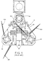
- FIG. 1 Skid rails 32 are shown which enable the skidding on and skidding off of equipment as will be discussed more fully below.
- Supply cranes 201 are typically provided on such jack-up platforms. However, supply cranes are usually limited to a lifting capacity of between 45 and 100 tons (4.57 to 10.16 x 10 4 kg). Supply cranes of this type do not have sufficient lifting capacity to function as construction cranes in remote, deep water fields.
- slot 202 which is useful for encompassing fixed platforms 14 (e.g., FIG. 10) of suitable size during work-over operations as is well known by those of ordinary skill in the art.
- the jack-up rig 12 can take the form of any of a wide variety of such structures. It is sufficient for purposes of understanding this description that the jack-up rig 12 be capable of two basic functions. First, the jack-up rig 12 includes a hull 20 (e.g., FIG. 6) that is sufficiently sealed against water intrusion that it is able to float on the surface of a body of water, such as the Gulf of Mexico. In this manner, the jack-up rig is readily transportable by floatation to a variety of locations.
- a hull 20 e.g., FIG. 6
- the jack-up rig 12 must necessarily include means for adjusting its platform or deck 22 to a variety of vertical heights.
- the jack-up rig 12 includes a plurality of leg members 24 that are movably connected to the hull 20 and can be raised and lowered at will.
- the leg members 24 are raised above the sea floor 26, allowing the hull 20 to float freely on the surface of the water.
- the deck 22 be raised to a height
- the leg members 24 are lowered, engaging the sea floor 26 (e.g., FIG. 6) and slowly raising the height of the deck 22 to a desired level.
- Raising and lowering the leg members 24 may be accomplished in any suitable manner, such as electric, hydraulic, pneumatic, or even internal combustion motors (not shown) connected by means of a pinion or other well known structures to a rack or series of racks (not shown) disposed on the leg members 24.
- Jack-up rigs 12 of this type when jacked-up provide a stable platform from which to conduct drilling or work-over operations. Because jack-up rigs can also be jacked-down and operated as barges, they have proved useful in transporting drilling packages between various platforms in remote locations. Heretofore, however, no one has been able to utilize a conventional, jack-up rig 12 to accomplish both drilling and construction crane functions. This is attributable to a number of reasons, including the size weight, and sensitivity to movement of conventional construction cranes.
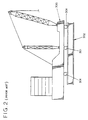
- FIG. 2 Illustrated in FIG. 2 is a schematic depiction of a side elevation of a conventional construction crane 300.
- the crane 300 is typically designed to roll upon rollers 301 on top of a ring 302.
- the diameter of ring 302 is 60 feet or greater.
- Construction cranes of this type are very susceptible to differential movement in the ring 302 in addition to movement generally.
- Some conventional construction cranes with large diameter rings 302 can tolerate less than 3/8 of an inch (0.9525 cm) deflection in the ring. This sensitivity to even slight deflections, as pointed out earlier, inhibits the use of a high capacity construction crane on a floating construction barge.
- the size and weight of such conventional construction cranes and the deck space required for the large diameter ring 302 has heretofore prevented their use upon even the larger, more stable jack-up rigs of the type illustrated in FIG. 1.
- skid rails 32 utilized by conventional jack-up rigs 12 define a skid fairway of fixed width, length, and unlimited height. Anything skidded along the deck 22 of jack-up rig 12 must not extend beyond this skid fairway. Otherwise, equipment that extends beyond the boundaries of the skid fairway would contact, and therefore cause damage to, other components of the jack-up rig 12. It is therefore a requirement of skidding that anything skidded move only within the skid fairway of the jack-up rig.
- the ring 302 of conventional construction cranes is wider than conventional jack-up rig skid fairways.
- the prior art provides no way for construction cranes to be skidded on and off of conventional jack-up rigs.
- We surmount this problem by attaching the ring 302 to a ring substructure 303 which is, in turn, mounted on a new and unique pony 304.
- the pony 304, the ring substructure 303, and the construction crane 300 are sometimes referred to herein as a construction crane package.
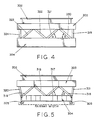
- FIG. 5 shows the width of the skid fairway in relation to the ring substructure 303 and pony 304. It is seen that the pony structure 304 elevates the ring 302 into a previously unappreciated zone above the skid rails 32. This new elevated zone has a greater unobstructed width than the conventional skid fairway. In this manner, the ring substructure 303, which would otherwise extend beyond the skid fairway width, is raised into a new fairway in an elevated zone above the conventional skid fairway which facilitates the movement of the construction crane package on and about jack-up rig 12.
- the support structure of the pony 304 must meet the conflicting requirements of rigidity and lightweight.
- FIG. 5 is a front view of ring substructure 303 mounted atop pony 304 in which the underlying support structure, is more readily discernable.
- Beams (or rails) 305 are shown and are understood to be conventional in design and construction to facilitate the skidding of the pony 304 along the skid rails 32 of jack-up rig 12.
- An arrow in FIG. 5 shows the direction of movement of the pony as it leaves the jack-up rig 12.
- Ring substructure 303 is, in one preferred embodiment, an eight-sided structure with eight nodes or plates 307.
- the lightweight yet rigid pony 304 is fabricated from tubular metal product such as 16" (0.4064 m) outside diameter pipe (1-1/4" wall thickness - 2.175 cm).
- tubular product be fabricated from a high strength, low alloy steel (e.g. ANSI 4300-series steel) that exhibits a yield strength of about 90 ksi (about 600 MPa) and yet retains adequate ductility and toughness.
- a high strength, low alloy steel e.g. ANSI 4300-series steel
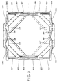
- FIGS. 3, 4 and 5 depict a preferred embodiment in which sixteen tubular members 316 - 331 intersect the ring substructure 303 at each of the eight nodes 307. Further, it is seen that the sixteen tubular members 316 - 331 can be grouped into four sets of four.
- Sets 1 and 2 comprise tubular members oriented generally normal to the direction of travel of the pony when skidding off the jack-up rig 12.
- Sets 1 and 2 include tubular members 316, 317, 318, 319, 324, 325, 326, and 327.
- Sets 3 and 4 comprise tubular members oriented generally parallel to the direction of travel of the pony when skidding off the jack-up rig 12.
- Sets 3 and 4 include tubular members 320, 321, 322, 323, 328, 329, 330, and 331.
- FIGS. 3, 4 and 5 show that the tubular members of sets 1 and 2 all lie within a plane normal to beams 305. In other words, the tubular members of Sets 1 and 2 do not extend out of the vertical plane in which they rest.
- support structures 316, 319, 322, and 324 make an angle of 50.5° with a horizontal axis; support structures 317, 318, 325, and 326 make an angle of 54.5° with the horizontal axis.
- FIG. 4 shows that the length of the pony 304 is substantially the same as the length of the ring substructure 303.
- FIG. 3 shows that tubular members 320, 321, 322, 323, 328, 329, 330, and 331 are angled from the beams 305 up to the nodes 307.
- support structures 320, 323, 328, and 331 make an angle of 44° with a horizontal and 12° with a vertical axis; support structures 321, 322, 329 and 330 make and angle of 55° with a horizontal axis and 8° with a vertical axis.
- FIG. 5 shows that the width of the pony structure 304 is less than the width of the ring substructure 303.
- the preferred embodiment of the pony 304 described herein facilitates the raising of the crane ring 302 out of the undersized skid fairway and into an elevated zone of sufficient width for the skidding on and off of a construction crane package.
- both the width and length could overhang the pony.
- other pony structures must be sufficiently rigid to meet conventional construction cranes limits on differential movement of the ring 302 and yet not be so heavy as to exceed the lifting capacity of a jack-up rig 12.
- the present invention facilitates the use of a conventional jack-up rig as both a construction crane platform relatively unaffected by the weather and movement of the seas, and a drilling or work-over platform.
- the present invention facilitates the operation of a crane package in the same weather criteria as a jack-up rig. For example, a crane package utilizing the present invention has been rated for a 15 year return storm in the Gulf of Mexico.
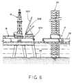
- the jack-up rig 12 is adjacent a dock 400 that has a conventional construction crane 300 mounted atop a pony 304 according to the present invention. Also shown on the dock 400 is a drilling package 18 and a skidbase 16. The skidbase 16 is more fully described below.
- the construction crane package 308 which comprises the conventional construction crane 300 and pony 304 is shown to be in the cribbed position for transportation. Also note that the crane counterweights (not shown) are not on the crane package 308 and will be transported on the deck of the jack-up rig 12 separately from crane package 308. Crane package 308 may be skidded on jack-up rig 12 and moved to a position sufficiently inboard on the deck 22 to facilitate transportation by floatation to a remote location.
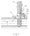
- FIG. 7 depicts the construction crane package 308 after it has been skidded onto the jack-up rig 12.
- Transferring the construction crane package from the dock onto the jack-up rig 12 involves skidding the construction crane package 308 along a set of rails 32 located on the deck 22 of the jack-up rig 12. This skidding process is accomplished using power commonly available on jack-up rigs 12 such as winches and hydraulic motors (not shown).
- the pony 304 is secured to the construction crane by a rigid yet lightweight structure that transfers loads evenly to the contact surfaces of the skid rails 305 and 32.
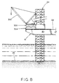
- FIG. 8 illustrates the jack-up platform in a raised position located in a remote sub-sea oil field.
- the crane package is shown skidded forward into position over the platform slot 202 (FIG. 1).
- the transportation cribbing has been removed from the crane package, the counterweights installed and the construction crane package 308 otherwise readied for service.
- the raised jack-up rig provides a relatively stable secure deck or platform from which the crane package can operate.
- the raised deck 22 of the jack-up rig is relatively unaffected by the wave and tidal action of the seas and is therefore relatively unaffected by the weather conditions of the remote maritime location.
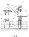
- FIG. 9 illustrates the construction package 308 being used from the raised deck 22 of a conventional jack-up rig 12 to construct a fixed platform 14. It should be appreciated that the present invention is not restricted to merely construction of fixed platforms but may also be used for the demolition of existing platforms.
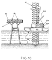
- FIG. 10 illustrates the hull 20 in the near floating condition after finalizing construction of the fixed platform 14.
- FIG. 10 also illustrates that the crane package 308 has been cribbed for transportation and has been skidded back into its traveling location.
- the jack-up rig 12 Once the jack-up rig 12 is in the fully floating configuration, the rig can be transported to another construction site for the construction or demolition of a fixed platform 14 or, the jack-up rig can return to the dock 400 indicated generally in FIG. 6.
- the construction crane package 308 can be skidded off or otherwise replaced on the dock 400, and the drilling package 26 and skid base 16 can be loaded onto the jack-up platform. If the drilling package is loaded onto the jack-up rig 12, the jack-up rig can then be returned to, for example, the fixed platform 14 shown in FIG. 9, and the drilling package can be skidded off onto the fixed platform. In remote regions where the dock 400 is too far away to be a convenient venue to store the crane package, the crane package 308 can be skidded onto and stored atop a fixed platform 14 as shown in FIG. 11. While the crane package 308 is stored, the jack-up rig can be used with a drilling package to drill or work-over wells. When drilling or work-over has been completed, the drilling package can be skidded off onto and may be stored atop a fixed platform 14.
- the present invention provides for the first time, a method and apparatus that facilitates the use of a single moveable structure, such as a conventional jack-up rig, to serve a dual function as a fixed drilling platform and as a fixed construction crane platform that is relatively unaffected by the wave and tidal action of the maritime environment.
- a single moveable structure such as a conventional jack-up rig
- the transfer method for the drilling package 10 occurs in two major steps: (1) sliding a skidbase 16 from the jack-up rig 12 to the fixed platform 14; and (2) sliding a drilling structure 18 from the jack-up rig 12 onto the skidbase 16.
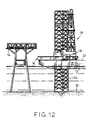
- FIG. 12 illustrates the jack-up rig 12 positioned immediately adjacent the fixed platform 14 with sufficient horizontal spacing therebetween to allow the deck 22 and skidbase 16 to clear the fixed platform 14 as it is raised to its proper vertical height.
- the leg members 24 are shown lowered to a position where the sea floor 26 is initially engaged. While only a single leg member 24 is illustrated in the drawing, it is readily understood by those skilled in the art that at least three leg members 24 are present to ensure stability of the jack-up rig 12.
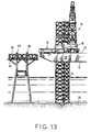
- FIG. 13 shows the deck of the jack-up rig 12 raised to the proper height for transferring the skidbase 16 from the jack-up rig 12 to the fixed platform 14.
- the height of the deck 22 is substantially, vertically aligned with a pair of capping beams 28, which extend across a deck portion 30 of the fixed platform 14 and are preferably positioned transverse to the major components of the skidbase 16 to provide adequate support therefor.
- a series of beams (not shown) are secured transversely across the capping beams 28 to provide the adequate support for the skidbase 16.
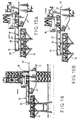
- FIG. 14 illustrates the skidbase 16 and drilling structure 18 being skidded toward the fixed platform 14 so that the skidbase 16 is transferred from the deck of the jack-up rig 12 to the fixed platform 14. It should be appreciated that at this time, only the skidbase 16 is actually being transferred to the fixed platform 14. The drilling structure 18 is transferred to the fixed platform 14 in a subsequent step described more fully in conjunction with the description of FIGS. 5 and 6.
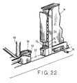
- the skidbase 16 is attached to the drilling structure 18 via a pinned connection (see FIG. 22) so that the weight of the drilling structure 18 prevents the skidbase 16 from tilting when it is in an intermediate, cantilevered position, extending from the deck 22 of the jack-up rig 12 toward the first capping rail 36 but unsupported by the capping rail 36.
- a pinned connection see FIG. 22
- the skidbase 16 is no longer cantilevered from the deck 22 and does not rely on the weight of the drilling structure 18 for support.
- the skidbase 16 is capable of fully supporting itself once the skidding process is substantially complete and the skidbase 16 spans the capping rails 28, as shown, for example, in FIG. 15A.
- the skidbase 16 is comprised of a support section 38 that extends between the capping rails 28 and a bridge section 40 that extends between the support section 38 and the jack-up rig 12.
- the bridge section 40 provides a structure on which the drilling structure 18 is moved across the gap between the jack-up rig and fixed platforms 12, 14 respectively to its operating position located on the support section 38.
- FIG. 15B illustrates the drilling structure 18 separated (e.g., by unpinning) from the skidbase 16 and being moved in a direction away from the skidbase 16 to allow the jack-up rig 12 to be raised to a level aligned with a top surface 42 of the skidbase 16.
- the top surface 42 of the skidbase 16 preferably includes a pair of rails 44 substantially identical to the rails 32 on the deck 22 of the jack-up rig 12.
- the rails 44 on the skidbase 16 are linearly identically aligned with the rails 32 on the deck 22 of the jack-up rig 12.
- connection means 47 between the bridge section 40 and the transom 46 is configured to automatically align and accurately connect the bridge section 40 to the transom 46 without the need for pins or other external devices to accomplish accurate alignment.
- the drilling structure 18 is skidded from the jack-up rig 12, across the bridge section 40, and onto the support structure 38 so that additional drilling or work-over operations may be performed from the fixed platform 14, as shown in FIG. 19.
- the deck 22 of the jack-up rig 12 may be lowered to the position illustrated in FIGS 18-19.
- a temporary deck 45 (FIG. 19) is preferably assembled over the slot 202 in the jack-up rig in a manner known to persons skill in the art. From this relative position of the deck 22 of the jack-up rig 12 and the fixed platform 14, the transfer of additional drilling materials from the jack-up rig 12 to the fixed platform 14 is facilitated.
- the connection means 47 automatically releases the interconnection between the jack-up rig 12 and the bridge section 40 so that the deck 22 of the jack-up rig 12 is free to be lowered to any desired position to facilitate material transfer.
- FIG. 19 shows a pipe rack 48 which extends between the temporary deck 45 of the jack-up rig 12 and the drilling structure 18 now positioned on the fixed platform 14.
- the pipe rack 48 is situated at an angle, which is a function of the height differential between the deck 22 of the jack-up rig 12 and the skidbase 16.
- the inclination of the pipe rack 48 encourages the transfer of drilling pipe 50 from a substantially horizontal position on or near the temporary deck 45 of the jack-up rig 12 to a vertical position in which it is used on the fixed platform 14.
- the drilling pipe 50 is threaded together to form a hollow core cylinder to which a drill bit or work-over tool (not shown) is attached and passed vertically into a well-bore (not shown) at the sea floor 26.
- the skidbase 16 includes a pair of parallel, spaced-apart beams 52, 54.
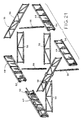
- the beams 52, 54 are interconnected by a plurality of open trusses 56 extending therebetween, as is more apparent from the exploded view of the skidbase 16 shown in FIG. 21.
- the open trusses 56 are designed to support the beams 52, 54 in their substantially upright position, and when connected together, cause the skidbase 16 to act as a substantially integral unit.
- the open trusses 56 and beams 52, 54 are assembled together by a plurality of pin and eye arrangements similar to those described below in conjunction with FIGS. 22 and 23.
- the skid rails 44 are formed on an upper surface of each of the beams 52, 54. It should be remembered that the skid rails 44 are used to transport the drilling structure 18 from the deck 22 into its desired position on the support section 38 of the skidbase 16.
- connection between the drilling structure 18 and the skidbase 16 is illustrated in FIG. 22. While only the connection to the beam 54 is illustrated, those skilled in the art readily recognize that the connection to the beam 52 is substantially similar.
- the drilling structure 18 and skidbase 16 are shown resting on the skid rail 32 on the deck 22 of the jack-up rig 12. Since this connection is not permanent and, in fact, is used only during the transfer of the skidbase 16 from the jack-up rig 12 to the fixed platform 14, the connection between the skidbase 16 and the drilling structure 18 is necessarily temporary.
- the drilling structure 18 includes a vertically arranged bifurcated flange 70 with a bore 72 extending perpendicularly therethrough.
- a tab section 74 on the beam 54 of the skidbase 16 has a perforated boss 75 with a width substantially similar to the spacing in the bifurcated flange 70.
- the bifurcated flange 70 extends about and encompasses the perforated boss 75 on the tab section 74 of the beam 54.
- a perforation or eye 76 extends through the tab section 74 and is generally aligned with eyes 72 in the bifurcated flange 70.
- a pin 78 is insertable through the eyes 72, 76 and can thereby temporarily interlock the beam 54 with the drilling structure 18.
- pin 78 is readily removable between the stages illustrated in FIGS. 15A and 15B to allow the drilling structure 18 to be skidded a short distance away from the skidbase 16. This short skidding process provides clearance for the deck 22 of the jack-up rig 12 to be raised level with the top of the skidbase 16.
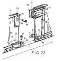
- the beams 52, 54 are of a two piece construction, defining the support structure 38 and the bridge section 40 of the skidbase 16. Connection of the bridge and support sections 40, 38 of the beam 54 is illustrated in FIG. 23. It should be appreciated that the connection between the bridge and support sections 40, 38 receives a very high loading force during the transfer of the drilling section 18 thereacross. In some cases the capping rails 28 may fully support the support section 38, and the bridge section 40 will be supported only at its connections with the support section 38 and the transom 46 of the jack-up rig 12.
- the bridge section 40 includes a pair of bifurcated flanges 80, 82 extending horizontally from opposite sides of a beam 54 of the bridge section 40.
- Each of the pair of bifurcated flanges 80, 82 includes a vertical eye 84, 86 extending therethrough and adapted for receiving a connection pin 88 therein.
- the support section 38 includes a pair of single perforated flanges 90, 92 extending horizontally therefrom and spaced above the skid rail 32 a distance sufficient to allow the single flanges 90, 92 to slide into the spaces in the bifurcated flanges 80, 82.
- the single flanges 90, 92 have corresponding eyes 94, 96 extending vertically therethrough and aligning with the boreholes 84, 86 so that the pin 88 is insertable therethrough to capture the bridge and support sections 40, 38 against relative movement therebetween.
- This first pinned location is located adjacent a lower surface of the bridge and support sections 40, 38.
- a second pinned connection is located adjacent an upper edge of the beam 54.
- the support section 38 includes a vertically arranged bifurcated flange 98 with a horizontal eye 100 extending therethrough.
- the bridge section 40 includes a tab section 102 having a perforated boss 103 with a width substantially similar to the spacing in the bifurcated flange 98.
- the eye 104 extends through the tab section 102 and is substantially alignable with the eye 100 so that a pin 106 can be inserted therethrough and capture the bridge and support sections 40, 38 against relative movement therebetween.
- the bifurcated flange 98 includes a tapered section 108 at its distal end so that the spacing in the bifurcated flanges 98 is increased at its distal end. This increased width ensures that a slightly misaligned tab section 104 will be guided into the bifurcated flange 98 as the bridge and support sections 40, 38 are moved toward one another.
- the bifurcated and single flanges 80, 82, 90, 92 are also tapered inward to enhance alignment of the bridge and support sections 40, 38. Referring now to FIGS. 24-29, the automatic connection means 47 between the transom 46 of the jack-up platform 12 and the bridge section 40 of the skidbase 16 is described in greater detail.
- FIG. 24 illustrates a side view of part of the transom 46 of the jack-up rig 12.
- the bridge section 40 is shown in phantom lines, interacting with the transom 46 to form the connection means 47.
- the connection means 47 includes a lock mechanism 120, which is comprised of three major components: a guide assembly 121, a stop 126, and a blade member 128.
- the guide assembly 121 takes the form of an upper and lower guide 122, 124, which, along with and the stop 126, are fixedly connected to the transom 46.
- the blade member 128 is fixedly connected to the bridge section 40 and, in the locked position, is captured within the guides 122, 124.
- the bridge section 40 rests on and is supported by the stop 126.
- connection means 47 operates during movement of the transom 46 in a generally upward vertical direction while the bridge section 40 remains substantially stationary. Therefore, it should be appreciated that the blade member 128 remains substantially stationary as the transom 46 and guide members 122, 124 are raised into contact with the blade member 128.
- the blade member 128 passes through the upper and lower guide members 122, 124 as the transom 46 moves upward until a lower section 130 of the bridge section 40 contacts the stop 126.
- the guide members 122, 124 do not directly support the weight of the bridge 40, but rather, guide the blade member 128 and, accordingly, the bridge 40 into proper orientation so that the skid rails 44, 32 are vertically aligned and spaced a preselected horizontal distance apart.
- the stop 126 supports the weight of the bridge 40 and the drilling structure 18 as it passes thereacross. Accordingly, the stop 126 is securely fastened to the transom 46 by any suitable means, such as, welding, threaded nut connection, or integral construction therewith. Further, a support bracket 132 preferably extends between the transom 46 and a lower surface 127 of the stop 126 to enhance its load carrying capabilities.
- the guide members 122, 124 and the blade member 128 are designed to guide the bridge section 40 into its proper orientation in two stages.
- the bridge section 42 is first roughly aligned by interaction between the blade 128 and the upper guide member 122. Thereafter, as the transom 46 continues to rise vertically, the lower guide member 124 engages the blade member 128 and provides a second, finer stage of alignment. This finer, second stage of alignment is enhanced by further interaction between the blade member 128 and the upper guide member 122.
- the blade member 128 has an upper section 134 and a lower section 136 of substantially different width.
- the widths of the upper and lower sections 134, 136 correspond to the different widths of the upper and lower guide members 122, 124.
- lower section 136 of the blade member 128 enters the upper guide member 122, it has a substantially narrower width than the width of the upper guide member 122.
- the blade member 128 is substantially narrower than the upper guide member 122, complete alignment between the bridge section 40 and the transom 46 is not yet accomplished. Rather, as the transom 46 continues to rise, the lower guide member 124 engages the lower section 136 of the blade member 128 to further align the bridge section 40 relative to the transom 46.
- the distance between the lowest portions of the upper and lower section 134, 136 generally corresponds to the distance between the upper and lower guide members 122, 124.
- the upper section 134 of the blade member 128 similarly engages the upper guide member 122.
- the blade member 128 is preferably tapered in an initial section or distal end 129 adjacent its lower section 136 and at the interface or intermediate section 131 between the upper and lower sections 134, 136.
- the width of the guide members 122, 124 are also preferably tapered top to bottom.
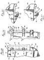
- FIGS. 26 and 27 Top views of the upper and lower guide members 122, 124 are shown in FIGS. 26 and 27 respectively.
- the upper and lower guide members 122, 124 are substantially similar in construction.
- Each of the guide members 122, 124 includes a pair of spaced apart, lateral movement limiting shoulders 140, 142; 144, 146, which define a width that corresponds respectively to the upper and lower section 134, 136 of the blade member 128.
- each of the guide members 122, 124 also includes a longitudinal movement limiting arm 148, 150 spaced from a base surface 152, 154.
- the arms 148, 150 capture the blade member 128 against horizontal movement away from the transom 46. Further, the arms 148, 150 have associated therewith, cam surfaces (see FIGS.
- a cam surface 156 associated with the lower guide member 124 can be seen attached to the arm 150 and extending into the space between the base 154 and the arm 150.
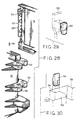
- FIG. 28 illustrates a perspective view of one side of the transom 46 positioned vertically below the skidbase 16 and generally aligned therewith so that upward movement of the transom 46, as indicated by the arrow 160, causes the guide members 122, 124 to engage the blade member 128.
- the cam surface 156 associated with the lower guide member 124 is illustrated in phantom lines.
- a second cam surface 162 associated with the upper guide assembly 122 is shown attached to a rear surface 163 of the blade member 128.
- the cam surfaces 162, 156 are illustrated in greater detail in FIGS. 29 and 30, respectively.
- the cam surfaces 156, 162 have at least one tapered surface thereon so that when the blade member 128 is engaged by the guide members 122, 124, the cam surfaces 156, 162 progressively urge the blade member 128 (and hence the skidbase 16) into precise alignment with the transom 46.
- One advantage in attaching the cam surface 156 to the lower guide member 124 while attaching the cam surface 162 to the blade member 128 is to allow the lower section 136 of the blade member 128 to freely pass through the upper guide member 122 without contact between a cam surface and the blade member 128. Rather, the cam action for precise alignment occurs when the transom 46 is near its extreme upward vertical position.
- blade member 128 and guide assembly 121 have been described in the singular form, it should be appreciated that operation of the lock 120 may be improved by the use of two spaced-apart assemblies.
- a pair of blade members 128 are mounted on the beams 52, 54 and interact with two sets of guide assemblies 121 and stops 126 located on the transom 46 of the jack-up platform 12.
- a stagewise alignment can be achieved between the skidbase 16 and the jack-up platform 12.
- the upper guide member 122 first encounters the lower section 136 of the blade member 128.
- the tapered initial section 129 of the blade member 128 is guided into a relatively rough alignment with the tapered lateral movement limiting shoulders 140, 142 of the upper guide member 122.
- This relatively rough alignment situates the blade member 128 to encounter the lower guide member 124.
- the lower guide member 124 engages the lower section 136 of the blade member 128, a finer alignment is achieved as the tapered lateral movement limiting shoulders 144, 146 cam the lower section 136 of the blade member 128 into position.
- the upper cam surface 162 urges the blade member 128 toward the base 152 of the upper guide member 122, and the lower cam surface 156 urges the blade member 128 toward the base 154 of the lower guide member 124.
- the upper and lower lateral movement limiting shoulders 140-144 with their tapered surfaces, and the upper and lower cam surfaces 162, 156 with their tapered surfaces coact with the stop member 126 to precisely and finely align the skidbase 16 with the jack-up rig 12 to position their respective skid rails 44, 32 adjacent each other for an advantageous transfer of the drilling structure 18 from the jack-up rig 12 to the fixed platform 14 and the back again.
- a surprisingly high degree of precision is achievable without the use of pins or mechanical devices in the practice of this invention.
Landscapes
- Engineering & Computer Science (AREA)
- Mechanical Engineering (AREA)
- General Engineering & Computer Science (AREA)
- Mining & Mineral Resources (AREA)
- Structural Engineering (AREA)
- Chemical & Material Sciences (AREA)
- Combustion & Propulsion (AREA)
- Ocean & Marine Engineering (AREA)
- Civil Engineering (AREA)
- Life Sciences & Earth Sciences (AREA)
- Geology (AREA)
- Environmental & Geological Engineering (AREA)
- General Life Sciences & Earth Sciences (AREA)
- Geochemistry & Mineralogy (AREA)
- Fluid Mechanics (AREA)
- Physics & Mathematics (AREA)
- Transportation (AREA)
- Earth Drilling (AREA)
- Jib Cranes (AREA)
Abstract
Claims (17)
- Ensemble de grue de construction (308) pour la pose/dépose par glissement d'une barge de forage auto-élévatrice (12), la base (302) de la grue de construction (300) étant plus large qu'un chenal de lancement défini par la largeur de rail de glissement de la plate-forme de levage (12), caractérisé en ce qu'il comporte:un poney ou dispositif de service (304) comportant une pluralité de poutres (305) pour soutenir la grue de construction (300), les poutres (305) étant essentiellement parallèles l'une à l'autre et espacées d'une largeur inférieure à la largeur du rail de glissement facilitant l'introduction du poney (304) dans le chenal de lancement de l'unité de levage (12);une pluralité de structures de support (316-331) dans le poney (304) qui relèvent la base (302) de la grue de construction (300) en zone surélevée au-dessus de la plate-forme de pose/dépose, la largeur de zone surélevée étant au minimum aussi grande que la largeur de la base (302) de la grue de construction (300), la zone surélevée facilitant le glissement en pose/dépose depuis l'unité de levage (12) et au dessus des obstacles hors du chenal de glissement, les structures de support (316-331) soutenant le porte à faux de la base de grue de construction (302) dont la largeur est supérieure à celle du chenal de glissement, les structures de support (316-331) facilitant le bon fonctionnement de la grue de construction (300) depuis la zone surélevée lorsque l'unité de levage (12) est relevée, la pluralité de structures de support (316-331) pouvant se déplacer lors du levage et de la descente de l'unité de levage (12).
- Ensemble de grue de construction (308) selon la revendication 1, pour lequel le rouleau directeur (304) comporte une surface inférieure et une surface supérieure (303) interconnectés par des structures de support (316-331) telles que la surface supérieure (303) est plus large que la surface inférieure.
- Ensemble de grue de construction (308) selon la revendication 1 ou la revendication 2, pour lesquelles certaines des structures de support (320-323, 328-331) sont orientées à un angle par rapport à l'axe vertical.
- Ensemble de grue de construction (308) selon l'une quelconque des revendications précédentes, comportant en outre une pluralité de plaques de support pour relever la base (302) de la grue de construction (300).
- Ensemble de grue de construction (308) selon la revendication 4, suivant laquelle certaines structures de support (316-331) sont reliées avec certaines plaques de support suivant des angles inégaux, de préférence au minimum la moitié des plaques de support étant raccordées aux structures de support (316-331) suivant des angles différents.
- Ensemble de grue de construction (308) selon l'une quelconque des revendications précédentes, selon lesquelles les structures de support (316-331) comportent une pluralité d'éléments structurels.
- Ensemble de grue de construction (308) selon l'une quelconque des revendications précédentes, comportant une sous-structure de grue (303), polygonale de préférence, accouplée à la structure de support (316-318) servant de support à un anneau de grue (302).
- Ensemble de grue de construction (308) selon la revendication 7, dont la largeur de sous-structure d'anneau de grue (303) est supérieure au rapport d'écart des rails et essentiellement le même qu'une largeur d'anneau de grue (302).
- Méthode de mise en oeuvre en chantier de construction d'une grue de construction (300) comportant les phases suivantes :la prévision d'une unité de levage (12) ayant une caisse (20) et une pluralité de jambages (24) adaptés pour le mouvement par rapport à la caisse (20), ladite caisse ayant un pont (22) ;la prévision d'un chenal de glissement (32) de largeur inférieure à une base (302) de la grue de construction (300) ;l'apport d'un ensemble de grue de construction (308) tel que défini à la revendication 1 comportant la grue de construction (300) et une structure qui relève la base (302) de la grue de construction (300) jusqu'en zone surélevée au dessus du pont (22), la zone surélevée étant de largeur supérieure à celle du chenal de lancement (32), permettant de glisser l'ensemble de la grue de construction (308) sur le pont (22) de la caisse (20) dans le chenal de lancement (32); le flottement de l'unité de levage (12) en une première position de service de la grue (300); la descente des jambages (24) de l'unité de levage (12) pour fixer le pont (22) ; et le fonctionnement de l'ensemble de grue de construction (308) au premier point depuis la zone surélevée.
- Méthode selon la revendication 9, comportant en outre les phases de levage des jambages (24) d'unité de levage (12) pour flotter la caisse (20) et flotter l'unité de levage (12) en une deuxième position.
- Méthode selon la revendication 10, comportant en outre la dépose de l'ensemble de grue de construction (308) depuis l'unité de levage (12) en la deuxième position ; permettant de glisser un élément de forage sur le pont (22) de l'unité de levage (12) ; le flottement de l'unité de levage (12) vers une troisième position, qui est au besoin la même que la première position, pour le service de l'élément de forage ; la descente des jambages (24) d'unité de levage (12) pour fixer le pont (22) ; la mise en service de l'unité de forage en ladite troisième position pour effectuer ledit forage ; et la remontée des jambages (24) d'unité de levage (12) pour flotter ladite caisse (20).
- La méthode selon la revendication 11, comportant en outre les phases de flottement de l'unité de levage en une quatrième position et le glissement en dépose depuis l'unité de levage (12) en quatrième position.
- La méthode selon la revendication 12, suivant laquelle les deuxième et quatrième positions se trouvent sur terre ferme.
- La méthode selon la revendication 12, suivant laquelle les deuxième et quatrième positions sont des plate-formes marines soit offshore.
- La méthode selon la revendication 10, suivant laquelle la deuxième position est un quai fixe sur terre, la méthode comportant le glissement de la grue de construction (308) hors du pont (22) de l'unité de levage (12) et sur le quai fixé sur terre ferme.
- La méthode selon la revendication 10, suivant laquelle la deuxième position est une plate-forme offshore fixé en mer, la méthode comportant le glissement de la grue de construction (308) depuis le pont (22) de l'unité de levage (12) et sur la plate-forme offshore fixée en mer.
- La méthode selon l'une quelconque des revendications 9 à 16, suivant laquelle les phases de levage sont assurées selon la même cadence que le levage est effectué par l'unité de levage (12) sans le poids supplémentaire de l'ensemble de la grue de construction (308).
Applications Claiming Priority (3)
| Application Number | Priority Date | Filing Date | Title |
|---|---|---|---|
| US86394592A | 1992-04-06 | 1992-04-06 | |
| US863945 | 1992-04-06 | ||
| PCT/US1993/003159 WO1993020289A1 (fr) | 1992-04-06 | 1993-04-06 | Procede et equipement concernant le transport et l'utilisation d'une installation de forage ou d'une grue avec une seule plate-forme |
Publications (3)
| Publication Number | Publication Date |
|---|---|
| EP0643787A1 EP0643787A1 (fr) | 1995-03-22 |
| EP0643787A4 EP0643787A4 (fr) | 1997-05-28 |
| EP0643787B1 true EP0643787B1 (fr) | 2002-09-25 |
Family
ID=25342168
Family Applications (1)
| Application Number | Title | Priority Date | Filing Date |
|---|---|---|---|
| EP93909474A Expired - Lifetime EP0643787B1 (fr) | 1992-04-06 | 1993-04-06 | Procede et equipement concernant le transport et l'utilisation d'une installation de forage ou d'une grue avec une seule plate-forme |
Country Status (5)
| Country | Link |
|---|---|
| US (1) | US5388930A (fr) |
| EP (1) | EP0643787B1 (fr) |
| AU (1) | AU4025593A (fr) |
| CA (1) | CA2133836C (fr) |
| WO (1) | WO1993020289A1 (fr) |
Families Citing this family (23)
| Publication number | Priority date | Publication date | Assignee | Title |
|---|---|---|---|---|
| US5960881A (en) | 1997-04-22 | 1999-10-05 | Jerry P. Allamon | Downhole surge pressure reduction system and method of use |
| US5997217A (en) * | 1998-05-11 | 1999-12-07 | Verret; Rodney J. | Shallow water well-drilling apparatus |
| US6467117B1 (en) * | 2000-09-12 | 2002-10-22 | General Electric Company | Light weight work platform with crane |
| US6520257B2 (en) | 2000-12-14 | 2003-02-18 | Jerry P. Allamon | Method and apparatus for surge reduction |
| US6491103B2 (en) | 2001-04-09 | 2002-12-10 | Jerry P. Allamon | System for running tubular members |
| US7419006B2 (en) * | 2005-03-24 | 2008-09-02 | Wzi, Inc. | Apparatus for protecting wellheads and method of installing the same |
| US20080028619A1 (en) * | 2006-06-23 | 2008-02-07 | The Stanley Works | Heavy duty material processing shears |
| US20070296229A1 (en) * | 2006-06-23 | 2007-12-27 | The Stanley Works | Grappling system |
| US20080243365A1 (en) * | 2007-03-30 | 2008-10-02 | Remedial (Cyprus) Pcl | Methods of holding station and mooring and elevating support vessel |
| US20080237170A1 (en) * | 2007-03-30 | 2008-10-02 | Remedial (Cyprus) Pcl | Extension Bridges and methods of tender assist |
| US20080247827A1 (en) * | 2007-03-30 | 2008-10-09 | Remedial (Cyprus) Pcl | Work-over rig assembly and methods thereof |
| US20100067989A1 (en) * | 2007-03-30 | 2010-03-18 | Brown Michael D | Vessel for transporting wind turbines and methods thereof |
| US20080237173A1 (en) | 2007-03-30 | 2008-10-02 | Remedial (Cyprus) Pcl | Arm assembly and methods of passing a pipe from a first vessel to a second vessel using the arm assembly |
| US20080237175A1 (en) * | 2007-03-30 | 2008-10-02 | Remedial (Cyprus) Pcl | Extension assemblies and methods thereof |
| US7815398B2 (en) | 2007-03-30 | 2010-10-19 | Remedial Cayman Limited | Methods of positioning an elevating support vessel |
| US20080237174A1 (en) * | 2007-03-30 | 2008-10-02 | Remedial (Cyprus) Pcl | Crane support apparatus and methods thereof |
| WO2010096373A2 (fr) | 2009-02-18 | 2010-08-26 | Shell Oil Company | Ensemble sabot de patin pour charger et transporter de grosses structures |
| NL2006407C2 (en) * | 2011-03-16 | 2012-09-18 | Heerema Marine Contractors Nl | Method for removing a hydrocarbon production platform from sea. |
| US9580977B2 (en) * | 2013-09-11 | 2017-02-28 | Woolslayer Companies, Inc. | Blowout preventer transport and handling system |
| US9488023B2 (en) * | 2014-06-27 | 2016-11-08 | Woolslayer Companies, Inc. | Blowout preventer storage, transport and lift skid assembly |
| US20160040383A1 (en) * | 2014-08-07 | 2016-02-11 | Chevron U.S.A. Inc. | Floating system integration methodology |
| AU2015203127C1 (en) * | 2015-05-28 | 2016-08-04 | Woodside Energy Technologies Pty Ltd | An lng production plant and a method for installation of an lng production plant |
| DK3693513T3 (da) * | 2019-02-08 | 2021-12-13 | Petrodec B V | Struktur og fremgangsmåde til dekommissionering af en offshoreplatform |
Family Cites Families (40)
| Publication number | Priority date | Publication date | Assignee | Title |
|---|---|---|---|---|
| US1894950A (en) * | 1929-10-23 | 1933-01-24 | Motor Terminals Co | Apparatus for transferring freight |
| US2489869A (en) * | 1948-03-01 | 1949-11-29 | Western Electric Co | Loading platform |
| US2644971A (en) * | 1949-11-18 | 1953-07-14 | Arthur E Rowe | Loading dock construction |
| US3001595A (en) * | 1954-05-26 | 1961-09-26 | De Long Corp | Multi-purpose derrick barge and method of use in oil well drilling and servicing |
| US2997852A (en) * | 1954-12-30 | 1961-08-29 | De Long Corp | Apparatus and method for reecting a supporting structure over a body of water |
| US2959015A (en) * | 1956-08-28 | 1960-11-08 | Jersey Prod Res Co | Method and apparatus for removing marine drilling rigs |
| US3011318A (en) * | 1957-07-30 | 1961-12-05 | Youngstown Sheet And Tube Co | Offshore drilling rig |
| US2934905A (en) * | 1957-12-16 | 1960-05-03 | Moore Corp Lee C | Barge-carried oil well drilling equipment |
| FR1214760A (fr) * | 1958-02-03 | 1960-04-12 | Bataafsche Petroleum | Procédé pour enlever une plate-forme d'un dispositif à supports placé dans l'eauou pour l'y poser et installation pour exécuter ce procédé |
| US3033525A (en) * | 1958-10-28 | 1962-05-08 | Dresser Ind | Force-transmitting device |
| US3150787A (en) * | 1960-08-08 | 1964-09-29 | Ct D Etudes Et D Applic Des Te | Handling apparatus |
| US3477235A (en) * | 1967-12-11 | 1969-11-11 | Crestwave Offshore Services In | Cantilevered offshore structure |
| US3716993A (en) * | 1971-01-18 | 1973-02-20 | M Sumner | Modular offshore structures system |
| US3894503A (en) * | 1973-04-06 | 1975-07-15 | Brown & Root | Method for converting a floatable barge into a semi-submersible vessel |
| GB1462775A (en) * | 1973-11-16 | 1977-01-26 | Alluvial Dredges Ltd | Floating support assemblies |
| US3952887A (en) * | 1974-04-16 | 1976-04-27 | Lutz David E | Vehicle loading and unloading apparatus |
| US3931778A (en) * | 1974-08-08 | 1976-01-13 | Raymond International, Inc. | Support barge method and apparatus |
| US4055264A (en) * | 1975-08-04 | 1977-10-25 | Brown & Root, Inc. | Deck section loading |
| US4224005A (en) * | 1975-12-10 | 1980-09-23 | James G. Brown & Associates, Inc. | Truss rig |
| US4065934A (en) * | 1975-12-10 | 1978-01-03 | James G. Brown & Associates, Inc. | Rig transport method |
| US4103503A (en) * | 1976-12-21 | 1978-08-01 | Dixilyn International, Inc. | Drilling substructure transfer system |
| FR2405182A1 (fr) * | 1977-10-04 | 1979-05-04 | Metalliques Entrepr Cie Fse | Procede et equipement pour la mise en place sur colonnes ancrees au fond, a partir d'un navire transporteur, de chargements, plates-formes ou analogues, pour installations au large des cotes |
| NO791030L (no) * | 1978-04-03 | 1979-10-04 | Brown & Root | Fremgangsmaate og innretning for fremstilling av et integrert dekk |
| NL7805807A (nl) * | 1978-05-29 | 1979-12-03 | Heusden Verolme Scheeps | Dokschip. |
| BR7804645A (pt) * | 1978-07-19 | 1980-01-22 | Petroleo Brasileiro Sa | Plataforma auto-elevatoria de perfuracao maritima |
| US4602894A (en) * | 1981-05-01 | 1986-07-29 | Marathon Manufacturing Company | Combination offshore drilling rig |
| JPS5880430U (ja) * | 1981-11-25 | 1983-05-31 | 日立造船株式会社 | 大型海洋構造物据付用作業船 |
| US4456404A (en) * | 1982-02-17 | 1984-06-26 | Atlantic Pacific Marine Corporation | Method and apparatus for positioning a working barge above a sea surface |
| US4483644A (en) * | 1982-09-15 | 1984-11-20 | Johnson Thomas P | Cantilevered mobile marine rig with hydraulic load equalizer |
| US4473321A (en) * | 1983-05-02 | 1984-09-25 | Chicago Bridge & Iron Company | Method of launching a large floatable object from a dock to water and delaunching it |
| US4583881A (en) * | 1984-05-29 | 1986-04-22 | Bethlehem Steel Corporation | Mobile, offshore, jack-up, marine platform adjustable for sloping sea floor |
| FR2581020A1 (fr) * | 1985-04-24 | 1986-10-31 | Marion Henri Albert | Procede de transport et de transfert d'une charge constituee d'un equipement complet d'un pont de plate-forme marine et moyens pour la mise en oeuvre du procede |
| IT1184238B (it) * | 1985-06-19 | 1987-10-22 | Saipem Spa | Procedimento per l'installazione della sovrastruttura in monoblocco di una piattaforma offshore ed attrezzature per la sua messa in pratica |
| US4874269A (en) * | 1986-07-21 | 1989-10-17 | Dysarz Edward D | Semi submersible device and method of transporting a marine superstructure and placing it onto or removing it from a marine structure |
| US4848967A (en) * | 1988-01-04 | 1989-07-18 | Exxon Production Research Company | Load-transfer system for mating an integrated deck with an offshore platform substructure |
| US4864957A (en) * | 1988-11-21 | 1989-09-12 | Diversified Technologies, Inc. | Apparatus and method for launch and recovery of watercraft onto and from the deck of a host vessel |
| US5032040A (en) * | 1989-10-31 | 1991-07-16 | Transworld Drilling Company | System for moving drilling module to fixed platform |
| US5052860A (en) * | 1989-10-31 | 1991-10-01 | Transworld Drilling Company | System for moving drilling module to fixed platform |
| US4938628A (en) * | 1989-10-31 | 1990-07-03 | Transworld Drilling Company | System for moving drilling module to fixed platform |
| US4973198A (en) * | 1989-12-28 | 1990-11-27 | Shell Oil Company | Offshore drilling rig transfer |
-
1993
- 1993-04-06 AU AU40255/93A patent/AU4025593A/en not_active Abandoned
- 1993-04-06 EP EP93909474A patent/EP0643787B1/fr not_active Expired - Lifetime
- 1993-04-06 CA CA002133836A patent/CA2133836C/fr not_active Expired - Lifetime
- 1993-04-06 WO PCT/US1993/003159 patent/WO1993020289A1/fr not_active Ceased
- 1993-12-30 US US08/176,282 patent/US5388930A/en not_active Expired - Lifetime
Also Published As
| Publication number | Publication date |
|---|---|
| WO1993020289A1 (fr) | 1993-10-14 |
| CA2133836A1 (fr) | 1993-10-14 |
| CA2133836C (fr) | 2004-01-20 |
| US5388930A (en) | 1995-02-14 |
| EP0643787A1 (fr) | 1995-03-22 |
| AU4025593A (en) | 1993-11-08 |
| EP0643787A4 (fr) | 1997-05-28 |
Similar Documents
| Publication | Publication Date | Title |
|---|---|---|
| US5388930A (en) | Method and apparatus for transporting and using a drilling apparatus or a crane apparatus from a single movable vessel | |
| EP1021624B1 (fr) | Procede et appareil d'installation offshore d'ensembles ponts pesant plusieurs tonnes, par exemple des ensembles ponts et des treillis | |
| US4714382A (en) | Method and apparatus for the offshore installation of multi-ton prefabricated deck packages on partially submerged offshore jacket foundations | |
| US6318931B1 (en) | Method and apparatus for the offshore installation of multi-ton packages such as deck packages and jackets | |
| US4108318A (en) | Apparatus for offshore handling and running of a BOP stack | |
| US7083004B2 (en) | Cantilevered multi purpose tower and method for installing drilling equipment | |
| US5139366A (en) | Offshore jackup rig locking apparatus and method | |
| JP3908282B2 (ja) | ジャッキアッププラットフォームのロック装置 | |
| KR101230424B1 (ko) | 고정형 석유굴착용 플랫폼의 요소를 이송, 설치 및분해하기 위한 구조물과 이러한 구조물을 이용하는 방법 | |
| US6149350A (en) | Method and apparatus for the offshore installation of multi-ton packages such as deck packages and jackets | |
| US6499914B1 (en) | Movable self-elevating artificial work island with modular hull | |
| US5975807A (en) | Method and apparatus for the offshore installation of multi-ton packages such as deck packages and jackets | |
| US4041711A (en) | Method and apparatus for quickly erecting off-shore platforms | |
| US4230190A (en) | Blow out preventer handling system | |
| US6203247B1 (en) | Drilling vessel with moveable substructure | |
| US4081163A (en) | Blow out preventer handling system | |
| US5290128A (en) | Method and apparatus for transferring a drilling apparatus from a movable vessel to a fixed structure | |
| US5248003A (en) | Apparatus and method for supporting the free end of a cantilever beam of a cantilevered jack-up rig | |
| WO2019066653A2 (fr) | Obturation et abandon d'un ou de plusieurs puits de forage à plateforme en mer d'une plate-forme en mer à l'aide d'un navire marin à vérin | |
| JPH1096212A (ja) | 橋梁の撤去方法 | |
| US4365787A (en) | Pipe string lift system | |
| CA2095618C (fr) | Methode et appareil servant a transferer un appareil de forage d'un vaisseau mobile a une structure fixe | |
| EP1005592B1 (fr) | Procede et appareil pour l'installation off-shore de blocs de plusieurs tonnes, tels que des blocs de ponts, et de treillis | |
| HK1007583B (en) | Method and apparatus for transferring a drilling apparatus from a movable vessel to a fixed structure |
Legal Events
| Date | Code | Title | Description |
|---|---|---|---|
| PUAI | Public reference made under article 153(3) epc to a published international application that has entered the european phase |
Free format text: ORIGINAL CODE: 0009012 |
|
| 17P | Request for examination filed |
Effective date: 19941104 |
|
| AK | Designated contracting states |
Kind code of ref document: A1 Designated state(s): GB NL |
|
| A4 | Supplementary search report drawn up and despatched |
Effective date: 19970408 |
|
| AK | Designated contracting states |
Kind code of ref document: A4 Designated state(s): GB NL |
|
| 17Q | First examination report despatched |
Effective date: 19991215 |
|
| GRAG | Despatch of communication of intention to grant |
Free format text: ORIGINAL CODE: EPIDOS AGRA |
|
| GRAG | Despatch of communication of intention to grant |
Free format text: ORIGINAL CODE: EPIDOS AGRA |
|
| GRAH | Despatch of communication of intention to grant a patent |
Free format text: ORIGINAL CODE: EPIDOS IGRA |
|
| GRAH | Despatch of communication of intention to grant a patent |
Free format text: ORIGINAL CODE: EPIDOS IGRA |
|
| GRAA | (expected) grant |
Free format text: ORIGINAL CODE: 0009210 |
|
| AK | Designated contracting states |
Kind code of ref document: B1 Designated state(s): GB NL |
|
| REG | Reference to a national code |
Ref country code: GB Ref legal event code: FG4D |
|
| PLBE | No opposition filed within time limit |
Free format text: ORIGINAL CODE: 0009261 |
|
| STAA | Information on the status of an ep patent application or granted ep patent |
Free format text: STATUS: NO OPPOSITION FILED WITHIN TIME LIMIT |
|
| 26N | No opposition filed |
Effective date: 20030626 |
|
| PGFP | Annual fee paid to national office [announced via postgrant information from national office to epo] |
Ref country code: NL Payment date: 20120426 Year of fee payment: 20 |
|
| PGFP | Annual fee paid to national office [announced via postgrant information from national office to epo] |
Ref country code: GB Payment date: 20120425 Year of fee payment: 20 |
|
| REG | Reference to a national code |
Ref country code: NL Ref legal event code: V4 Effective date: 20130406 |
|
| REG | Reference to a national code |
Ref country code: GB Ref legal event code: PE20 Expiry date: 20130405 |
|
| PG25 | Lapsed in a contracting state [announced via postgrant information from national office to epo] |
Ref country code: GB Free format text: LAPSE BECAUSE OF EXPIRATION OF PROTECTION Effective date: 20130405 |